Page 213 of 2103

ENGINE OVERHAUL
Items
Engine coolant temperature sensor
Fuel and emission control parts
EGR tube
EGR valve
Intake manifold
11 8
Intake manifold air temperature sensor
Manifold absolute pressure sensor
Intake manifold
Exhaust manifold
Exhaust manifold
Camshaft and cam follower
Cvlinder head cover
Bearing head cover
No.5 12
No.1, 628 20
Cvlinder head and
valve.
7
21 . 4
231 7 :
23 17
Cylinder head bolt
Oil pan and oil pump
Oil filter
Adapter
Oil
Oil pick-up tube
Oil pump
Oil pump
Relief valve retaining cap
Long bolt87
Short bolt2820
21,
12
2 8
23
54
Oil pump cover
Piston, connecting rod and cylinder block
Connecting rod cap bolt
1 2
2720
Knock sensor 10I
SEALANTS
Engine coolant temperature sensor
switch
Camshaft bearing cap
Oil pump
Bed plate to oil pan gasket
Oil pressure switch Bed plate to cylinder block Specified sealant
Loctite 24200 or equivalent
Loctite 24200 or equivalent
Loctite 51817 or equivalent
Loctite 51817 or equivalent
Loctite 18718 or equivalent
Loctite 24200 or equivalent
Loctite 19614 or equivalent
TSB Revision
Page 227 of 2103
ENGINE OVERHAUL Cooling System
COOLING SYSTEM COMPONENTS
REMOVAL
(1) Remove water pump attaching screws to engine.
Thermostat
Thermostat Gasket
(2) Remove level gauge.
(3) Remove exhaust manifold cover.
(4) Remove water hose.
(5) Remove water pipe.
(6) Remove O-ring.
(7) Remove thermostat housing bolts and housing.
(8)Remove thermostat, discard gasket and clean both ga sket
sealing surfaces.
(9) Remove engine coolant temperature sensor.
Remove switch.
TSB Revision
Page 277 of 2103

On-vehicle Service
A/C COMPRESSOR DRIVE BELT TENSION ADJUSTMENT
1. Loosen tension pulley fixing nut A.
2. Adjust belt tension with adjusting bolt B.
Standard value:
When a new belt isWhen a used belt is
installed installed
Tension
382-411255-333
(Ibs.)
Deflection8.5-7.5
mm (in.)
3. Tighten fixing nut A. Tightening torque: 23-26 Nm
4.Check the belt deflection amount and readjust if ne ces-
sary.
Caution
This check should be carried out after turning the
crankshaft one full rotation or more
the forward
direction (to the right).
IGNITION TIMING CHECK
1.Before inspection and adjustment set vehicle in the follow-
ing condition.
lEngine coolant temperature:
lLights, electric cooling fan and all accessories: OFF
Transaxle: Neutral (P range on vehicles with
2. Turn the ignition switch to OFF and connect the scan
tool to the data link connector.
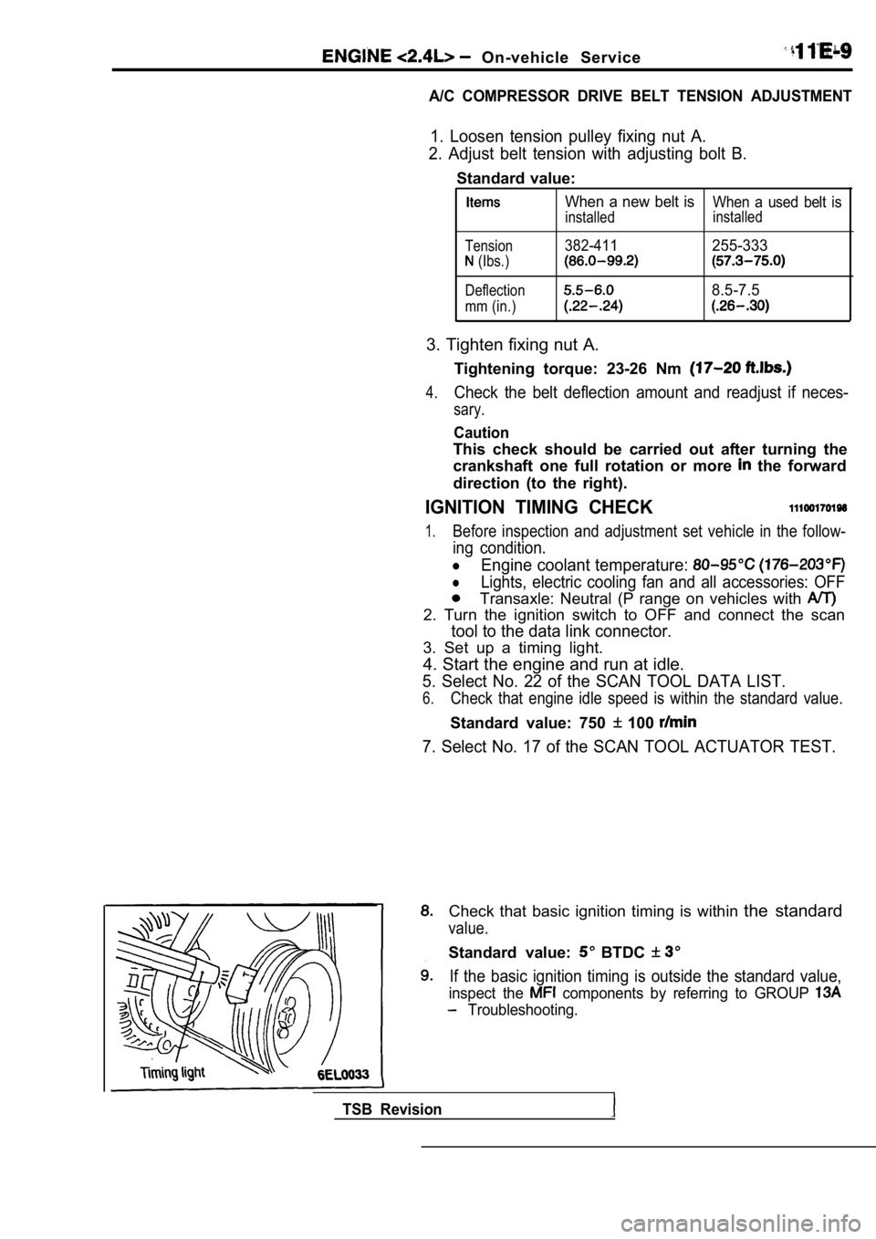
3. Set up a timing light.
4. Start the engine and run at idle.
5. Select No. 22 of the SCAN TOOL DATA LIST.
6.Check that engine idle speed is within the standard value.
Standard value: 750 100
7. Select No. 17 of the SCAN TOOL ACTUATOR TEST.
Check that basic ignition timing is within the standard
value.
Standard value: BTDC
If the basic ignition timing is outside the standar d value,
inspect the components by referring to GROUP
Troubleshooting.
TSB Revision
Page 278 of 2103

ENGINE O n - v e h i c l e
Press the scan tool clear key (select aforced driving
cancel mode) to release the ACTUATOR TEST
NOTE
If the test is not a forced driving will continue
for 27 minutes. Driving under this condition may damage
the engine.
Check that the actual ignition timing is at the st andard
value.
Standard value: Approx. BTDC
NOTE
Ignition timing is variable within about even under
normal operating.
2. And it is automatically further advanced by abou t
from BTDC at higher altitudes.
CURB IDLE SPEED CHECK
Before inspection and adjustment, set vehicles in the
following condition.
lEngine coolant temperature:
lLights, electric cooling fan and all accessories: OFF
lTransaxle: Neutral (P range on vehicles with A/T)
2. Turn the ignition switch to OFF and connect the scan
tool to the data link connector.
3. Select No. 17 of the SCAN TOOL ACTUATOR TEST
4. Check the basic ignition timing.
Standard value: BTDC
5. Run the engine at idle for 2 minutes.
6. Select No. 22 of the SCAN TOOL DATA LIST.
7. Check the curb idle speed.
Standard value: 750 100
NOTE
The idle speed is controlled automatically by the i dle air
control system.
8. If the idle speed is outside the standard value, check
the components by referring to GROUP Trou-
bleshooting.
IDLE MIXTURE CHECK
Before inspection, set vehicles in the following co ndition:
lEngine coolant temperature:
lLights, electric cooling fan and all accessories: O FF
lTransaxle: Neutral (P range on vehicles with
2. Turn the ignition switch to OFF and connect the scan
tool to the data link connector.
3. Select No. 17 of the SCAN TOOL ACTUATOR TEST.
4.Check that the basic ignition timing is within the standard
value..
Standard value:
TSB Revision
Page 279 of 2103

On-vehicle
Run the engine.
8. Set CO, HC tester.
7. Check the CO contents and the HC contents at idle.
Standard value:
CO contents: 0.5% or less
HC contents: 100 ppm or less
8. the standard value is exceeded, check the following
items:
l Diagnostic output
l Closed-loop control (When the closed-loop control
is carried out normally, the output signal of the heated
oxygen sensor and
at idle.)
l
Injector
lIgnition coil, spark plug
l system the
l Evaporative emission
Compression ,
NOTE,
Replace the three-way CO and
HC contents do not
the value.
(even though the
of the” on
all items.)
PRESSURE CHECK
1.Before inspection, check that the engine oil, start er and
battery are normal. Also, set the vehicle to the fo llowing
condition:
lEngine coolant temperature:
lLights, electric cooling fan and all accessories: O FF
lTransaxle: Neutral (P range on vehicles with
2. Disconnect the spark plug cables.
3. Remove all of the spark plugs.
4. Disconnect the crankshaft position sensor
NOTE
Doing this will prevent the engine control unit fro m carrying
out ignition and fuel injection.
TSB Revision
Page 280 of 2103

ENGINEOn-vehicle
5. Cover the spark plug hole with a shop towel etc., and
after the engine has been cranked, check that no foreign
material is adhering to the shop towel.
Caution
1.Keep away from the spark plug hole when crank-
ing.
2. If compression is measured with water, fuel,
etc., that has come from cracks inside the
these materials will become heated and gush
out from the spark plug hole, which is dangerous.
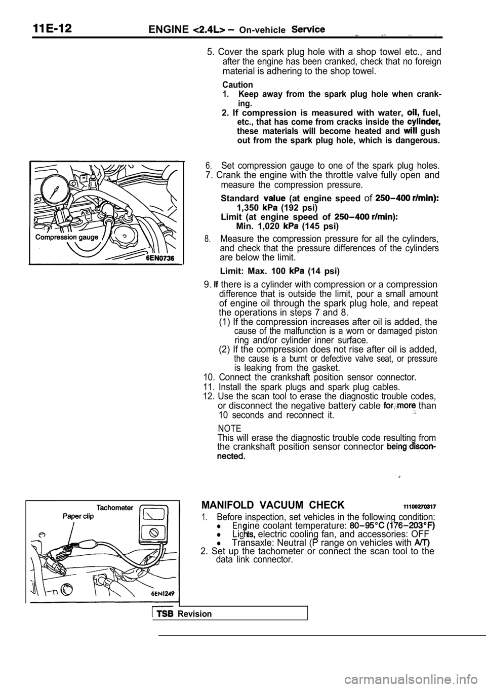
6.Set compression gauge to one of the spark plug hole s.
7. Crank the engine with the throttle valve fully open and
measure the compression pressure.
Standard (at engine speed of
1,350 (192 psi)
Limit (at engine speed of
Min. 1,020 (145 psi)
8.Measure the compression pressure for all the cylind ers,
and check that the pressure differences of the cyli nders
are below the limit.
Limit: Max. 100 (14 psi)
9. there is a cylinder with compression or a compression
difference that is outside the limit, pour a small amount
of engine oil through the spark plug hole, and repe at
the operations in steps 7 and 8.
(1) If the compression increases after oil is added , the
cause of the malfunction is a worn or damaged pisto n
ring and/or cylinder inner surface.
(2) If the compression does not rise after oil is added,
the cause is a burnt or defective valve seat, or pr essure
is leaking from the gasket.
10. Connect the crankshaft position sensor connecto r.
11. Install the spark plugs and spark plug cables.
12. Use the scan tool to erase the diagnostic troub le codes,
or disconnect the negative battery cable than
10 seconds and reconnect it.
NOTE
This will erase the diagnostic trouble code resulting from
the crankshaft position sensor connector
MANIFOLD VACUUM CHECK
1.Before inspection, set vehicles in the following co ndition:
lEn
lLig electric cooling fan, and accessories: OFF
ine coolant temperature:
lTransaxle: Neutral (P range on vehicles with
2. Set up the tachometer or connect the scan tool t o the
data link connector.
Revision
Page 284 of 2103
.
4 . 9 N m
\ / X L - -3.6
. .
8. Accelerator cable connection9. air control motor connector
10. Heated oxygen sensor connector
11. Engine coolant temperature gauge
unit connector
12. Engine coolant temperature sensorconnector13. Ignition power transistor connector
14. Throttle position sensor connector
Capacitor connector16. Manifold differential pressure
20. Crankshaft position sensor
connector21. Air conditioning compressor
connector22. Evaporative emission purge sole-
noid valve
23. Control wiring harness
24. Brake booster vacuum hose
connection High-pressure fuel connection
26. Fuel return hose connection --
. .. .
17.18.
sensor connector
Injector connectors
Ignition coil connector
19. Camshaft position sensor connector 27.
water nose A 28. Water hose connection29. Vacuum hoses connection
TSB Revision
Page 336 of 2103
ENGINE OVERHAUL intake Manifold
sealant
3 mm
bead sealant
INSTALLATION SERVICE ,
S E A L A N T TO
HOUSING
Specified sealant:Mitsubishi Genuine Part No.
or equivalent
NOTE
(1) Be sure to install the housing quickly while sealant
is wet (within 15 minutes).
(2) After installation, keep the sealed area away f rom the
oil and coolant for approx. one hour.
SEALANT APPLICATION TO WATER
FITTING
S p e c i f i e d s e a l a n t :
Mitsubishi Genuine Part No.’ or equivalent
NOTE
(1) Be sure to install the housing quickly while th e sealant
is wet (within 15 minutes).
(2) After installation, keep the sealed area away f rom the
oil and coolant for approx. one hour.
SEALANT APPLICATION COOLANT
T E M P E R A T U R E S E N S O R
Specified sealant:
Nut Locking Part No. or equivalent
SEALANT APPLICATION TO ENGINE COOLANT TEMPERATURE GAUGE UNIT
Specified sealant:
ATD Part No. 8680 or equivalent
TSB Revision