1990 MITSUBISHI SPYDER clutch
[x] Cancel search: clutchPage 1822 of 2103
STEERING Power Steering Hoses Engine (Turbo) and Engine>
REMOVAL SERVICE
BRAKE FLUID RESERVOIR ASSEMBLY
REMOVAL
Disconnect the brake fluid level sensor connector and
the brake fluid reservoir assembly from the dash panel with
the hose still attached.
NOTE
Place the removed reservoir assembly in a place whe re it
will not be a hindrance when removing and installin g the
power steering gear box, and tie it with a cord.
CLUTCH FLUID RESERVOIR ASSEMBLY
REMOVAL
Remove the clutch fluid reservoir assembly from the dash
panel with the hose still attached.
NOTE
Place the removed reservoir assembly in a place whe re it
will not be a hindrance when removing and installin g the
power steering hoses, and tie it with a cord.
A/C COMPRESSOR REMOVAL
Disconnect the A/C compressor connector remove the
compressor from the compressor bracket with the hos e still
attached.
NOTE
Place the removed in a where it will not be a hindrance when
removing and installing the power steering hoses an d tie
it with a cord.
Caution
Do not damage the joint between the A/C hose and the
A/C pipe.
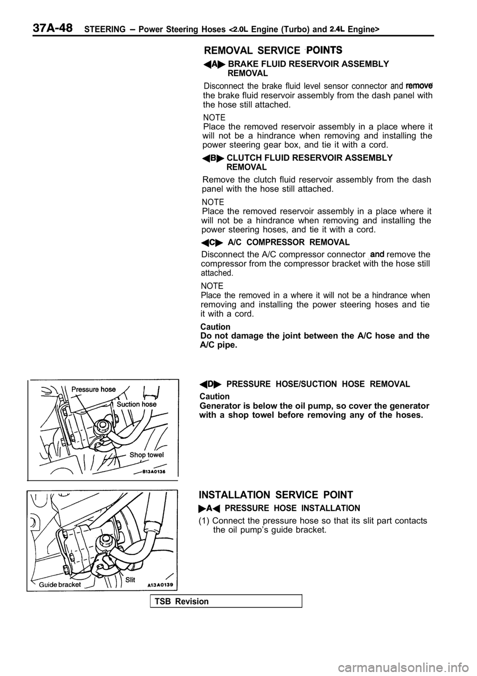
PRESSURE HOSE/SUCTION HOSE REMOVAL
Caution
Generator is below the oil pump, so cover the gener ator
with a shop towel before removing any of the hoses.
INSTALLATION SERVICE POINT
PRESSURE HOSE INSTALLATION
(1) Connect the pressure hose so that its slit part contacts
the oil pump’s guide bracket.
TSB Revision
Page 2041 of 2103
CONTENTS
AIR CONDITIONING SWITCH . . . . . . . . . . . . . . 23
LUBRICANTS. . . . . . . . . . . . . . . . . . . . . . . . . . . . . .5
BLOWER ASSEMBLY AND RESISTOR*
. . . .26
COMPRESSOR AND TENSION PULLEY
ENGINE (NON-TURBO)>.. . . . . . . . . . . .38
COMPRESSOR AND TENSION PULLEY
ENGINE (TURBO) AND ENGINE>
ON-VEHICLE SERVICE. . . . . . . . . . . . . . . . . . . . .8
Charging. . . . . . . . . . . . . . . . . . . . . . . . . . . . . . . . . . .10
Compressor Noise Check. . . . . . . . . . . . . . . . . . . .16
Compressor Drive Belt Adjustment . . . . . . . . . . . .9
. . . . . . . . . . . . . . . . . . . . . . . . . . . . . . . . . . . . . . . .31Dual Pressure Switch Check. . . . . . . . . . . . . . . . . .9
Handling Tubing and Fittings. . . . . . . . . . . . . . . . .15
CONDENSER AND CONDENSER
46Idle-up Operation Check. . . . . . . . . . . . . . . . . . . . .17FAN MOTOR. . . . . . . . . . . . . . . . . . . . . . . . . . . . . .Magnetic Clutch Test. . . . . . . . . . . . . . . . . . . . . . . . .9
COOLING UNIT . . . . . . . . . . . . . . . . . . . . . . . . . . . 28
GENERAL INFORMATION3. . . . . . . . . . . . . . . . . .
Performance Test. . . . . . . . . . . . . . . . . . . . . . . . . . .14
Power Relay Check . . . . . . . . . . . . . . . . . . . . . . . . .17
Safety Precautions. . . . . . . . . . . . . . . . . . . . . . . . . . .4Receiver Drier Test. . . . . . . . . . . . . . . . . . . . . . . . . .9
. . . . . . . . . . . . . . . . . . . . .15HEATER CONTROL ASSEMBLY*19Refrigerant Leak Repair. . . . . . . . . .
Sight Glass Refrigerant Level Test . . . . . . . . . . . .8
HEATER UNIT AND HEATER CORE*. . . . . . . 24CONTINUED ON NEXT PAGE
WARNINGS REGARDING SERVICING OF SUPPLEMENTAL RESTRA
INT SYSTEM (SRS) EQUIPPED VEHICLES
WARNING!
(1)
improperservice or maintenance of any component of the SRS, or any SRS-related component, can lead to
the SRS inoperative).
(2) Service or maintenance of any SRS component or SRS-related component must be performed only at an authorized
MITSUBISHI dealer.
(3)MITSUBISHI dealer personnel must thoroughly review this manual, and especially its GROUP Supplemental straint System (SRS) and GROUP 00 Maintenance Service before beginning any service or maintenance of any com-
ponent of the SRS or any SRS-related component.
N O T EThe SRS includes the following components: SRS ECU, SRS warning light, air bag module, clocksprin g and interconnecting wiring.Other components (that may have to be removed/installed in connection with SRS service or maintenance) are indi-
cated in the table of contents by an asterisk(*).
Page 2043 of 2103
HEATER, AIR
AND VENTILATION General Information
GENERAL INFORMATION
The heater system uses a two-way-flow full-air-mixThe A/C system is basically the same as the
system that features high performance and lowtional system, but a new refrigerant system
operating noise, and includes an independent facebeen adopted as a response to
air blowing function and a air bypass function.use of chlorofluorocarbons. ,
Specifications
Heater unit type Two-way-flow full-air-mix system
Heater
controlassembly Dial and lever type
Compressor model
Engine (Turbo) and Scroll type
Engine>
Engine (Non-turbo)>Inclined-plate type
Dual pressure switch (psi)High-pressure switch OFF: 3,140 ON: 2,550 (370)
Low-pressureswitchOFF: 200 ON: 220 (32)
Refrigerant and quantity
(oz.) Approx. 700 740
OPERATION
Condenser fan and radiator fan control
lFor the operation of each fan, refer to COOLING
SYSTEM TROUBLESHOOTING.
Compressor control
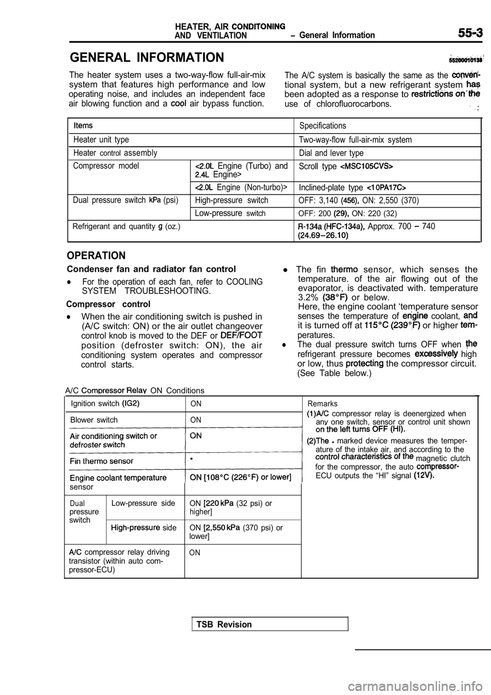
lWhen the air conditioning switch is pushed in (A/C switch: ON) or the air outlet changeover
control knob is moved to the DEF or
position (defroster switch: ON), the air
conditioning system operates and compressor
control starts.
l The fin sensor, which senses the
temperature. of the air flowing out of the
evaporator, is deactivated with. temperature
3.2%
or below.
Here, the engine coolant ‘temperature sensor
senses the temperature of coolant,
it is turned off at or higher
peratures.
lThe dual pressure switch turns OFF when
refrigerant pressure becomes high
or low, thus the compressor circuit.
(See Table below.)
A/C ON Conditions
Ignition switch
Blower switch
ON
ON Remarks
compressor relay is deenergized when
anv one switch, sensor or control unit shown
l marked device measures the temper-
ature of the intake air, and according to the
magnetic clutch
for the compressor, the auto
ECU outputs the “HI” signal
sensor
DualLow-pressure side ON (32 psi) or
pressure
higher]
switch side ON (370 psi) or
lower]
compressor relay driving
transistor (within auto com-
pressor-ECU)ON
TSB Revision
Page 2045 of 2103

HEATER, AIR Service
AND VENTILATION Special Tools
SERVICE SPECIFICATIONS
IStandard value ‘I
speed E n g i n e ( T u r b o ) a n d
EngineII
Engine (Non-turbo)I
up speed
Resistor (for blower motor) LO
100 in Neutral
1.83
MHI 0.31
Revolution pick up sensor standard resistance
Engine (Non-turbo)>
185
[when ambient temperature is
Refrigerant temperature switch ON (continuity) tempe rature
Engine (Turbo) and
Engine>OFF (no continuity) temperature
Approx. or less
Approx. or more
(until the temperature drops to approx.
when OFF)
Air gap (Magnetic clutch) mm (in.)
Engine (Turbo) and
Engine
Engine (Non-turbo)I
LUBRICANTS
ItemsSpecified lubricants Quantity
Each connection of refrigerant line ND-OIL 8 Engine (Non-turbo)>, SUN PAG 56 As required
Engine (Turbo) and Engine>
Lip seal of the compressor ND-OIL 8
Engine (Non-turbo)>As required
Compressor refrigerant unit lubricant SUN PAG 56
lubricant
Engine (Turbo) and Engine>
ND-OIL 8
Engine (Non-turbo)>
SPECIAL TOOLS
ToolTool number and nameSupersession Application
367Armature mounting nut of com-
e S p e c i a l s p a n n e r removal and installation
Engine (Turbo) and
Engine>
386
Pin
TSB Revision
Page 2046 of 2103

HEATER, AIR
AND VENTILATION Troubleshooting
TROUBLESHOOTING
PROCEDURES
Trouble
symptom
When the ignitior
switch is “ON”,
the
does not
operate.
conditioning
does not
when
he air outlet
knob is
noved to the
or
position. Problem cause
compressor clutch relay
is defective
Magnetic clutch is defective
Refrigerant leak or overfilling
of refrigerant
Dual pressure switch is defec-
tive
A/C switch is defective Blower switch is defective
Fin
sensor is defective
Refrigerant temperature switch
is defective
Engine (Tur-
bo) and
Engine>
Automatic compressor-ECM
is defective
Revolution pick up sensor is
defective
Engine (Non-turbo)>
A/C compressor relay is de-
fective
1
Dual pressure switch is defec-
tive
Defroster switch is defective
TSB Revision
Magnetic clutch is defective
Refrigerant leak or overfilling
of refrigerant Remedy
Reference ReferencepagepageEngine
Engine(Non-turbo) (Turbo) Engine
Replace A/C compressor clutch 55-1855-18
relay
Replace the armature plate, rotor55-34
or clutch coil
Replenish the refrigerant, repair
0
the leak or take out some of therefrigerant
Replace the dual pressure switch 55-45
Replace the A/C switch 55-2355-23
Replace the blower switch55-22 55-22
Replace the fin sensor
Replace the refrigerant tempera-
ture switch
Replace the automatic
Replace the revolution pick up
sensor
55-26
Replace A/C compressor clutch55-18
relay
Replace the armature plate, rotor55-34
or clutch coil
Replenish the refrigerant, repair
the leak or take out some of the
refrigerant
Replace the dual pressure switch55-45
the defroster switch55-22 55-22
the blower switch55-225 5 - 2 2
temperature Replace the refrigerant tempera-
is defective
ture switch
compressor-ECU isReplace the automatic 55-26
sor-ECU
pick up sensor is
Replace the revolution pick up
sensor Engine
Page 2048 of 2103
55-8HEATER, AIR
AND VENTILATION Troubleshooting/On-vehicle Service
Engine (Non-turbo)>
12
Sensor ground
Automatic compressor-ECM power
supply (output side)
Fin sensor power supply
o v
The ignition switch, blower switch andBattery positive
switch areall ONvoltage
The ignition switch, blower switch and
A/C switch are all ON
TROUBLESHOOTING HINTS
l R e f e r t o C O O L I N G S Y S T E M
SHOOTING.
Refer to
Terminal No.Name of Signal
Check requirements Terminal voltage
compressor clutch relay
When the compressor ON conditions Battery positive
are satisfied voltage
2Automatic compressor-ECM groundov
4Automatic compressor-ECM power
The ignition switch, blower switch and Battery positive
supply (input side) switch are all ONvoltage
5Automatic compressor-ECM powerTheignition switch is ONBattery positive
voltage
Engine (Turbo) and Engine>I
O N - V E H I C L E S E R V I C E
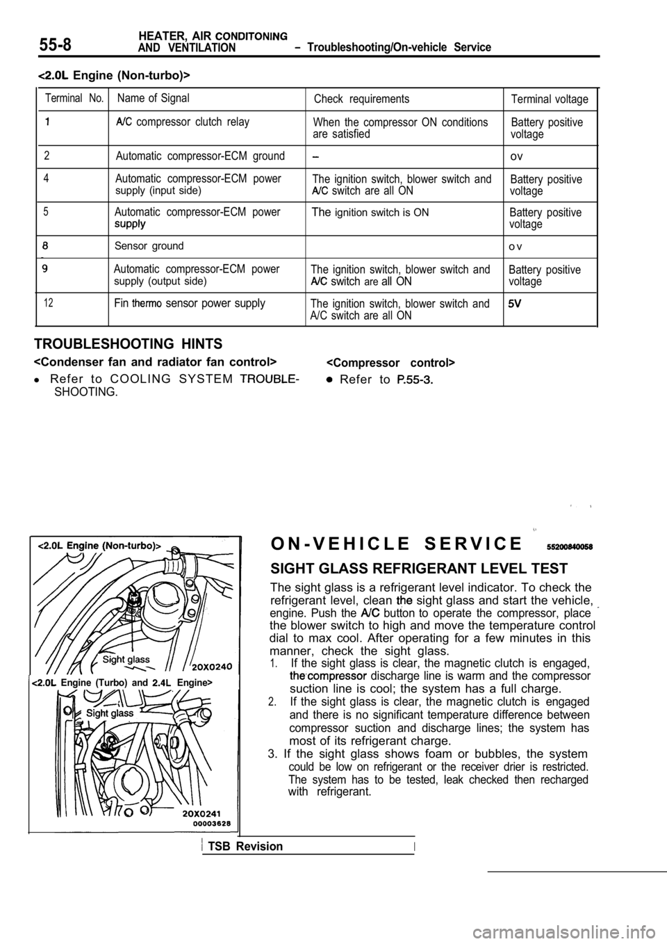
SIGHT GLASS REFRIGERANT LEVEL TEST
The sight glass is a refrigerant level indicator. T o check the
refrigerant level, clean
sight glass and start the vehicle,
engine. Push the button to operate the compressor, place
the blower switch to high and move the temperature control
dial to max cool. After operating for a few minutes in this
manner, check the sight glass.
1.If the sight glass is clear, the magnetic clutch is engaged,
discharge line is warm and the compressor
suction line is cool; the system has a full charge.
2.If the sight glass is clear, the magnetic clutch is engaged
and there is no significant temperature difference between
compressor suction and discharge lines; the system has
most of its refrigerant charge.
3. If the sight glass shows foam or bubbles, the sy stem
could be low on refrigerant or the receiver drier is restricted.
The system has to be tested, leak checked then rech arged
with refrigerant.
TSB RevisionI
Page 2049 of 2103
HEATER, AIR
AND VENTILATION On-vehicle Service
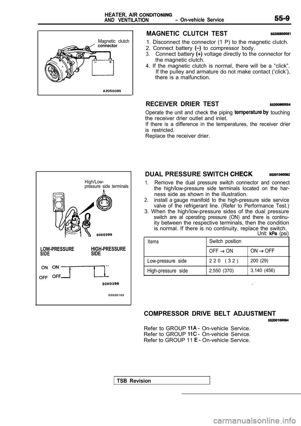
Magnetic clutch
High/Low-
pressure side terminals
LOW-PRESSURE HIGH-PRESSURESIDESIDE
0 0 0 0 0 1 6 9
MAGNETIC CLUTCH TEST
1. Disconnect the connector (1 P) to the magnetic c
lutch.
2. Connect battery
to compressor body.
3.Connect battery voltage directly to the connector for
the magnetic clutch.
4. If the magnetic clutch is normal, there will be a “click”.
If the pulley and armature do not make contact (‘cl ick’),
there is a malfunction.
RECEIVER DRIER TEST
Operate the unit and check the piping touching
the receiver drier outlet and inlet.
If there is a difference in the temperatures, the r eceiver drier
is restricted.
Replace the receiver drier.
DUAL PRESSURE SWITCH
1.Remove the dual pressure switch connector and conne ct
the high/low-pressure side terminals located on the har-
ness side as shown in the illustration.
2.installagauge manifold to the high-pressure side service
valve of the refrigerant line. (Refer to Performanc e Test.)
3. When the high/low-pressure sides of the dual pre ssure
switch are at operating pressure (ON) and there is continu-
ity between the respective terminals, then the condition
is normal. If there is no continuity, replace the s witch.
Unit: (psi)
ItemsSwitch position
OFF
ONON OFF
Low-pressure side2 2 0 ( 3 2 )200 (29)
High-pressure side2,550 (370) 3,140 (456)
COMPRESSOR DRIVE BELT ADJUSTMENT
Refer to GROUP On-vehicle Service.
Refer to GROUP
On-vehicle Service.
Refer to GROUP 11
On-vehicle Service.
TSB Revision
Page 2054 of 2103
HEATER, AIR
AND VENTILATION On-vehicle Service
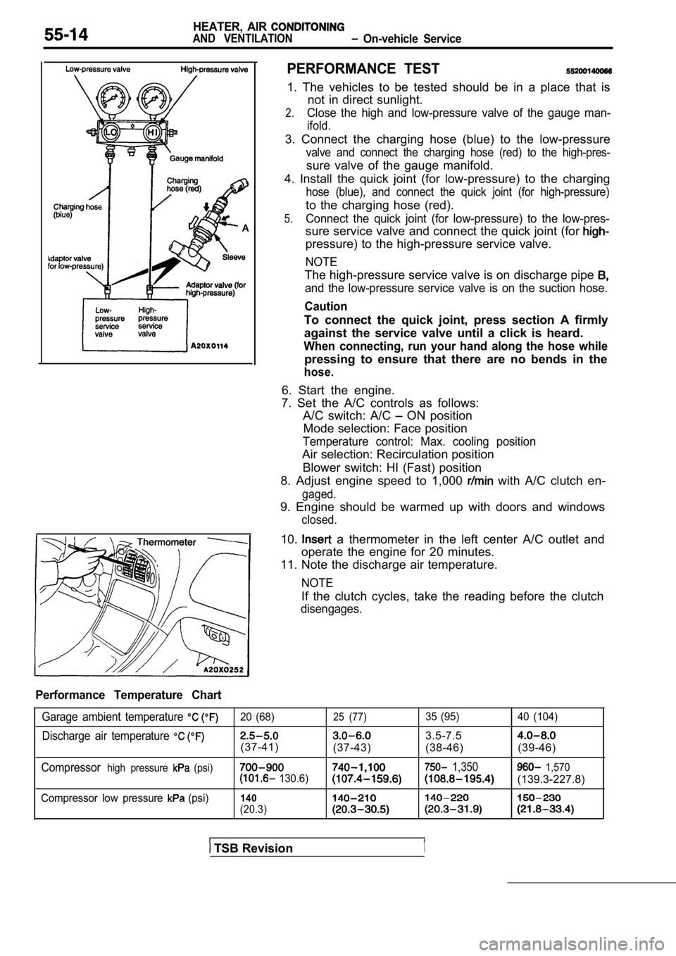
PERFORMANCE TEST
1. The vehicles to be tested should be in a place that is
not in direct sunlight.
2.Close the high and low-pressure valve of the gauge man-
ifold.
3. Connect the charging hose (blue) to the low-pres sure
valve and connect the charging hose (red) to the high-pres-
sure valve of the gauge manifold.
4. Install the quick joint (for low-pressure) to th e charging
hose (blue), and connect the quick joint (for high- pressure)
to the charging hose (red).
5.Connect the quick joint (for low-pressure) to the low-pres-
sure service valve and connect the quick joint (for
pressure) to the high-pressure service valve.
NOTE
The high-pressure service valve is on discharge pip e
and the low-pressure service valve is on the suction hose.
Caution
To connect the quick joint, press section A firmly
against the service valve until a click is heard.
When connecting, run your hand along the hose while
pressing to ensure that there are no bends in the
hose.
6. Start the engine.
7. Set the A/C controls as follows: A/C switch: A/C
ON position
Mode selection: Face position
Temperature control: Max. cooling position
Air selection: Recirculation position
Blower switch: HI (Fast) position
8. Adjust engine speed to 1,000
with A/C clutch en-
gaged.
9. Engine should be warmed up with doors and window s
closed.
10. a thermometer in the left center A/C outlet and
operate the engine for 20 minutes.
11. Note the discharge air temperature.
NOTE
If the clutch cycles, take the reading before the c lutch
disengages.
Performance Temperature Chart
Garage ambient temperature 20 (68)25 (77)35 (95) 40 (104)
Discharge air temperature 3.5-7.5
(37-41)
(37-43) (38-46) (39-46)
Compressorhigh pressure (psi) 1,350 1,570 130.6)(139.3-227.8)
Compressor low pressure (psi)140
(20.3)
TSB Revision1