1990 MITSUBISHI SPYDER clutch
[x] Cancel search: clutchPage 2056 of 2103
6HEATER, AIR
AND VENTILATION On-vehicle Service
COMPRESSOR NOISE CHECK
You must first know the conditions when the noise occurs. These conditions are: weather, vehicle speed,
in gear or neutral, engine temperature or any other special conditions.
Noises that develop during A/C operation can often be misleading. For example: what sounds like a
failed front bearing or connecting rod, may be caus ed by loose bolts, nuts, mounting brackets, or a
loose clutch assembly. Verify accessory drive belt tension (power steering or generator).
Improper accessory drive belt tension can cause a m isleading noise when the compressor is engaged
and little or no noise when the compressor is disen gaged.
Drive belts are speed-sensitive. That is, at differ ent engine speeds, and depending upon belt tension,
belts can develop unusual noises that are often mis taken for mechanical problems within the compressor .
ADJUSTMENT
1. Select a quiet area for testing. Duplicate conditions as much as possible. Switch compressor on
and off several times to clearly identify compresso r noise. To duplicate high ambient
head pressure), restrict air flow through condenser . Install manifold gauge set sure discharge
pressure doesn’t exceed 2,070 (300 psi).
2. Tighten all compressor mounting bolts, clutch mo unting bolt, and compressor drive belt. Check to
assure clutch coil is tight (no rotation or wobble) .
3. Check refrigerant hoses for rubbing or interfere nce that can cause unusual noises.
4. Check refrigerant charge. (Refer to
5. Recheck compressor noise as in Step 1.
6. If noise still exists, loosen compressor mountin g bolts and retorque. Repeat Step 1.
7. If noise continues, replace compressor and repea t Step 1.
Revision
Page 2058 of 2103
Engine (Turbo)>HEATER,
AIRAND VENTILATION On-vehicle Service
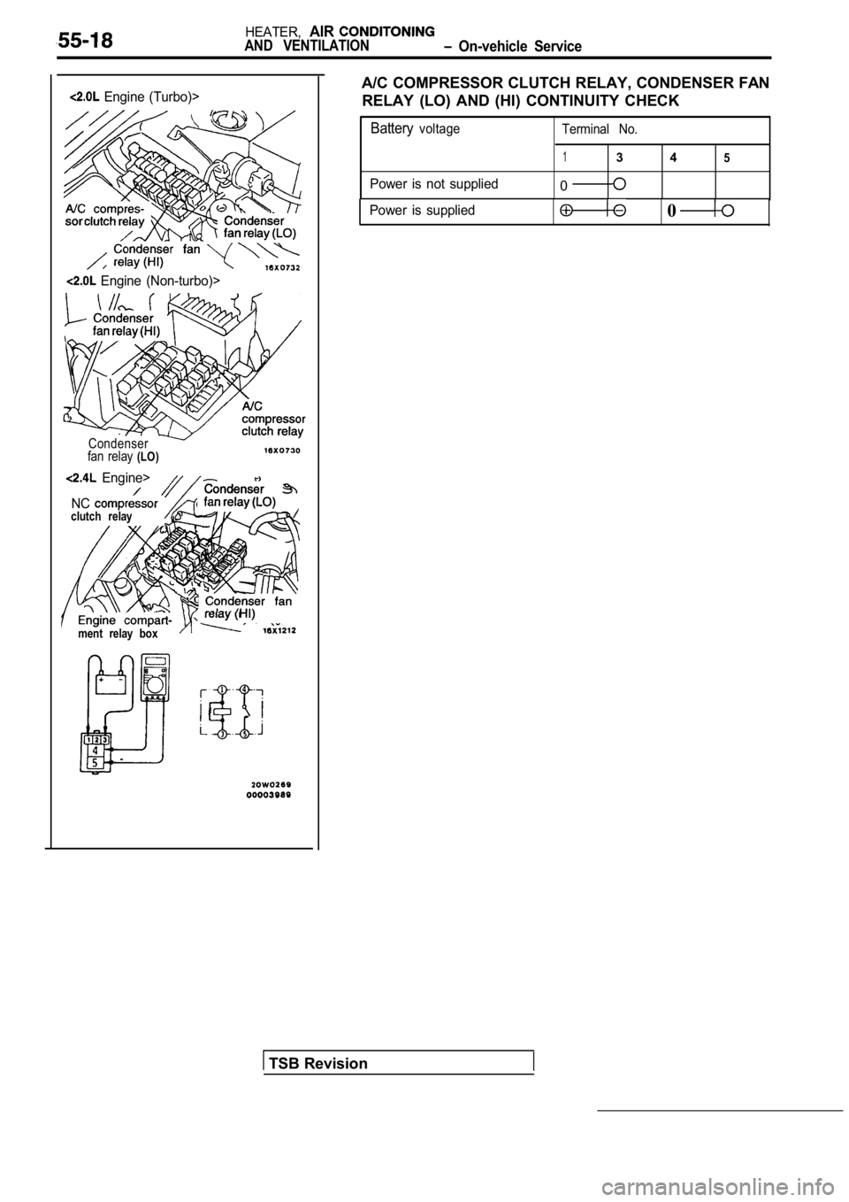
A/C COMPRESSOR CLUTCH RELAY, CONDENSER FAN
RELAY (LO) AND (HI) CONTINUITY CHECK
Batteryvoltage Terminal No.
13 45
Power is not supplied0
Engine (Non-turbo)>
Condenser
fan relay (LO)
Engine>
NC
clutch relay
ment relay box
Power is supplied0
TSB Revision
Page 2075 of 2103
HEATER, AIR Compressor and Tension Pulley
AND VENTILATION Engine (Turbo) and Engine>55-35
Clutch coil
Clutch coilSnap-ringI
Crankshaft
Serration notch
NUT REMOVAL
Use the special tools to remove the nut.
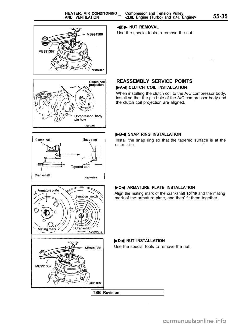
REASSEMBLY SERVICE POINTS
CLUTCH COIL INSTALLATION
When installing the clutch coil to the A/C compress
or body,
install so that the pin hole of the A/C compressor body and
the clutch coil projection are aligned.
SNAP RING INSTALLATION
Install the snap ring so that the tapered surface i s at the
outer side.
ARMATURE PLATE INSTALLATION
Align the mating mark of the crankshaft and the mating
mark of the armature plate, and then’ fit them toge ther.
NUT INSTALLATION
Use the special tools to remove the nut.
TSB Revision
Page 2076 of 2103
55-36HEATER, AIR
AND VENTILATION
Compressor and Tension Pulley
Engine (Turbo) and
Feeler gauge
temperature
switch
AIR GAP ADJUSTMENT
Check whether or not the air gap of the clutch is w ithin the
standard value.
Standard value: mm
NOTE
If there is a deviation of the air gap from the value,
make the necessary adjustment by adjusting the numb er of
shims.
INSPECTION
lCheck the of the armature for scoring or bluing.
lCheck the surface of the rotor for scoring or bluing.
l Check the sealing surfaces for cracks, scratches an d
deformation.
lCheck the front housing for cracks or scoring on the sealing
surfaces.
lCheck the compressor shaft for scoring.
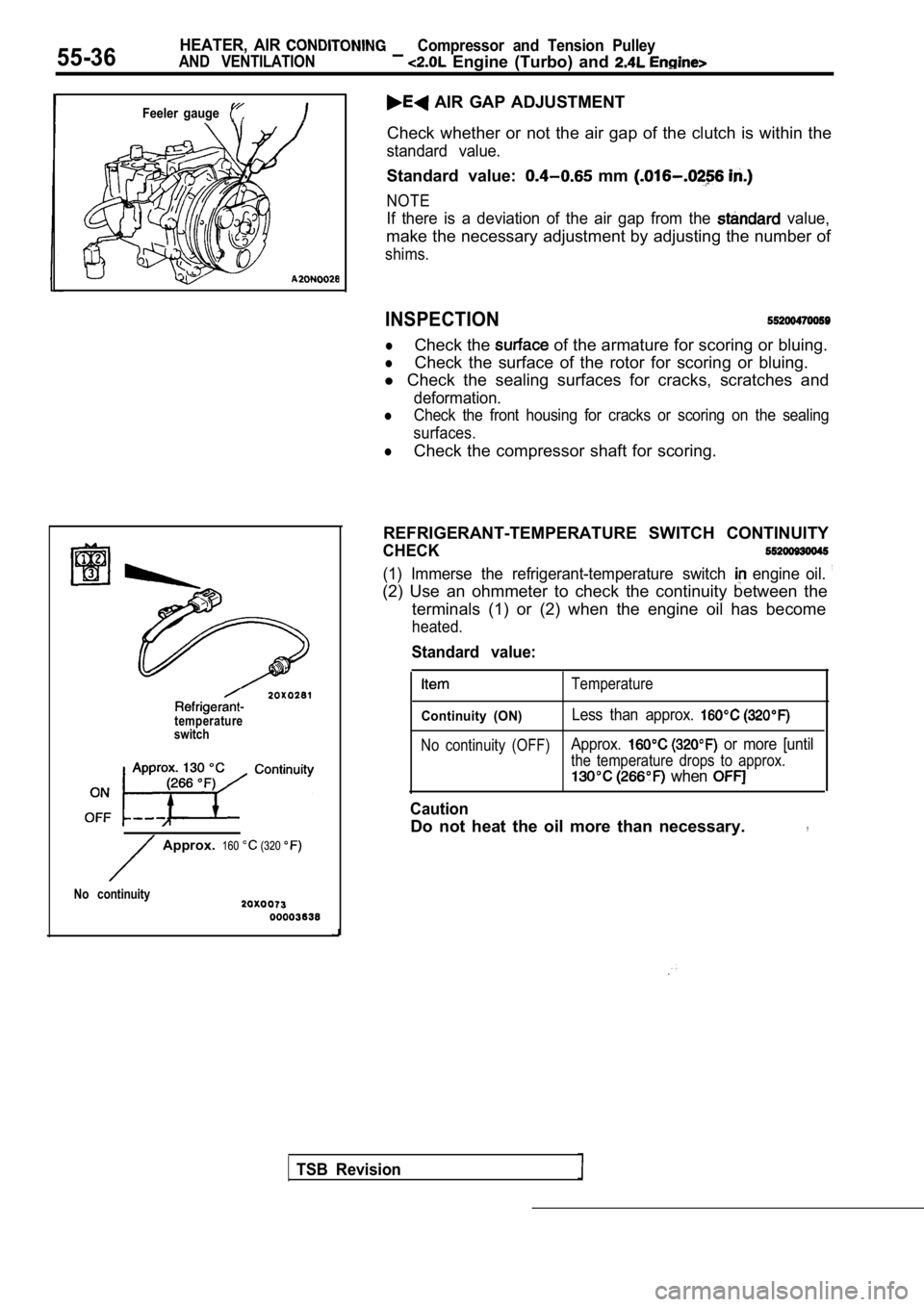
REFRIGERANT-TEMPERATURE SWITCH CONTINUITY
CHECK
(1) Immerse the refrigerant-temperature switch engine oil.
(2) Use an ohmmeter to check the continuity between the
terminals (1) or (2) when the engine oil has become
heated.
TSB Revision
Approx. 160 (320
No continuity
Standard value:
Temperature
Continuity (ON)Less than approx.
No continuity (OFF)Approx. or more [until
the temperature drops to approx.
when
Caution
Do not heat the oil more than necessary.,
Page 2080 of 2103
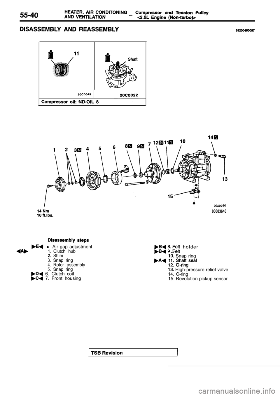
00003640
l Air gap adjustment1.Clutch hub2.Shim3.Snap ring4.Rotor assembly5.Snap ring 6. Clutch coil 7. Front housing
h o l d e r
Snap ring
High-pressure relief valve14. O-ring15. Revolution pickup sensor
Page 2081 of 2103
![MITSUBISHI SPYDER 1990 Service Repair Manual and Tension
Engine (Non-turbo)>
Bolt mm in.)]
Socket
Deep socket
(14 mm
in.)]
TSB
HUB REMOVAL
(1) Remove the clutch hub mounting bolt.
(2) Tighten a
mm in.) bolt into the ho MITSUBISHI SPYDER 1990 Service Repair Manual and Tension
Engine (Non-turbo)>
Bolt mm in.)]
Socket
Deep socket
(14 mm
in.)]
TSB
HUB REMOVAL
(1) Remove the clutch hub mounting bolt.
(2) Tighten a
mm in.) bolt into the ho](/manual-img/19/57345/w960_57345-2080.png)
and Tension
Engine (Non-turbo)>
Bolt mm in.)]
Socket
Deep socket
(14 mm
in.)]
TSB
HUB REMOVAL
(1) Remove the clutch hub mounting bolt.
(2) Tighten a
mm in.) bolt into the hole of the
clutch hub to remove the serration assembly the shaft
and the clutch hub.
SEAL INSTALLATION
Use a 21 mm in.) socket to install the shaft seal so
that the O-ring assembly side is facing the front h ousing.
FELT, FELT HOLDER INSTALLATION
After installing the felt in the felt holder, them to the
front housing using a 14 mm
deep socket.
FRONT HOUSING INSTALLATION
(1) Apply compressor oil to the shaft.
Compressor oil: ND-OIL 8
(2) Install the front housing without damaging the shaft seal
lip.
(3) After installing the front housing, install the clutch hub
mounting bolt to the shaft, and check that the breakaway
torque is within the torque value.
Breakaway torque:
Nm (4 or less
Page 2082 of 2103
55-42
Pin
Main unit of conditioningcompressor
Compressor side
connector
2
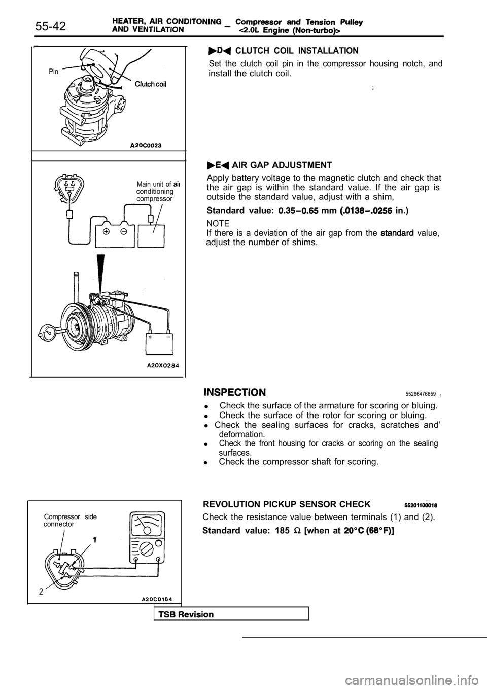
CLUTCH COIL INSTALLATION
Set the clutch coil pin in the compressor housing n otch, and
install the clutch coil.
AIR GAP ADJUSTMENT
Apply battery voltage to the magnetic clutch and ch eck that
the air gap is within the standard value. If the ai r gap is
outside the standard value, adjust with a shim,
Standard value:
mm in.)
NOTE
If there is a deviation of the air gap from the value,
adjust the number of shims.
55266476659
l Check the surface of the armature for scoring or bl
uing.
l Check the surface of the rotor for scoring or bluin
g.
l Check the sealing surfaces for cracks, scratches an d’
deformation.
lCheck the front housing for cracks or scoring on the sealing
surfaces.
l Check the compressor shaft for scoring.
REVOLUTION PICKUP SENSOR CHECK
Check the resistance value between terminals (1) an d (2).
Standard value: 185
[when at
Page 2093 of 2103

ALPHABETICAL
A
ABS OPERATIONCheck. . . . . . . . . . . . . . . . . . . . . . . . . . . . . . . . . . .
. . . . . . . . . . . . . . . . . . . . . . . . . . . . . . . . . . .
ABS-ECU. . . . . . . . . . . . . . . . . . . . . . . . . . . . . . . . . . . . . . . . .
. . . . . . . . . . . . . . . . . . . . . . . . . . . . . . . . . . . . . . . . .
ACCELERATOR CABLE. . . . . . . . . . . . . . . . . . . . . . . . . . . . . . . .Adjustment. . . . . . . . . . . . . . . . . . . . . . . . . . . . . . . . . . . . . . . . .
Check. . . . . . . . . . . . . . . . . . . . . . . . . . . . . . . . . . . . . . . . . . . . .ACCELERATOR PEDAL. . . . . . . . . . . . . . . . . . . . . . . . . . . . . . . .
ADAPTER, Transfer Case . . . . . . . . . . . . . . . . . .
AERO PARTS. . . . . . . . . . . . . . . . . . . . . . . . . . . . . . . . . . . . . . . .
AIR BAG CONTROL UNIT (SRS-ECU), SRS. . . . . . . . . . .AIR BAG MODULES. . . . . . . . . . . . . . . . . . . . . . . . . . . . . . . . .
Deployed Disposal Procedures. . . . . . . . . . . . . . . . . . . . .
Disposal Procedures. . . . . . . . . . . . . . . . . . . . . . . . . . . . .
Disposal. . . . . . . . . . . . . . . . . . . . . . . . . . . . .
AIR CLEANER ELEMENT, Maintenance. . . . . . . . . . . . . . . . . .AIR CONDITIONING SWITCH
ENGINE (NON-TURBO)>. . . . . . . . . . . . . . ENGINE (TURBO) AND .AIR COOLER, charge. . . . . . . . . . . . . . . . . . . . . . . . . . . . . . . . . . .
AIR FILTER. . . . . . . . . . . . . . . . . . . . . . . . . . . . . . . . . . . . . . . . . .
ALIGNMENT
Front Wheel, Check and Adjustment. . . . . . . . . . . . . . . . .
Wheel, Rear, Check and Adjustment. . . . . . . . . . . . . . . . . . .AMPLIFIER. . . . . . . . . . . . . . . . . . . . . . . . . . . . . . . . . . . . . . . . . .
GEAR AND TRANSFER DRIVE GEAR SET
. . . . . . . . . . . . . . . . . . . . . . . . . . . . . . . .
. . . . . . . . . . . . . . . . . . . . . . . . . . . . . . . . . . . . . . . .
ANTENNA.
ARM Compression, Lower
. . . . . . . . . . . . . . . . . . . . . . . . . . . . . . .Lateral, Lower. . . . . . . . . . . . . . . . . . . . . . . . . . . . . . . . . . .
Lower. . . . . . . . . . . . . . . . . . . . . . . . . . . . . . . . . . . . . . . . . . . . .
Toe Control. . . . . . . . . . . . . . . . . . . . . . . . . . . . . . . . . . . . . . . .
Trailing. . . . . . . . . . . . . . . . . . . . . . . . . . . . . . . . . . . . . . . . . . . .
Upper
Suspension>. . . . . . . . . . . . . . . . . . . . . . . . . . .ARMS, Rocker . . . . . . . . . . . . . . . . . . . . . . . . . . .11AUTO-CRUISE CONTROL. . . . . . . . . . . . . . . . . . . . . . . . . . . . .
AUTO-CRUISE CONTROL CABLE, Check andAdjustment. . . . . . . . . . . . . . . . . . . . . . . . . . . . . . . . . . . . . . . . . . .
AUTO-CRUISE CONTROL COMPONENT, Check. . . . . . . . .AUTO-CRUISE CONTROL SYSTEM, Operation Check. . . .AUTOMATIC TRANSAXLE FLUID, Maintenance. . . . . . . . . .AUTOMATIC TRANSAXLE CONTROL COMPONENTCheck
ENGINE (NON-TURBO)>.. . . . . . . . . . . .Layout ENGINE (NON-TURBO)>. . . . . . . . . . . .AUTOMATIC TRANSAXLE KEY INTERLOCK AND SHIFT LOCKMECHANISMS
ENGINE (NON-TURBO)>. . . . . . . . . . . . . . . . . . .
ENGINE (TURBO) AND ENGINE>.. . . . . . .AXLE
Rear, Total Backlash Check. . . . . . . . . . . . . . . . . . . . . . . . . .
AXLE OIL
Rear, Maintenance
. . . . . . . . . . . . . . . . . . . . . . . . . . . . . . . . .
BACK-UP LIGHT. . . . . . . . . . . . . . . . . . . . . . . . . . . . . . . . . . . . .BALL JOINT, Tie Rod End, Breakaway Torque Check. . . . .BALL JOINT SEALS, Maintenance. . . . . . . . . . . . . . . . . . . . . .
BARStabilizer Suspension>. . . . . . . . . . . . . . . . . . . . .
Suspension>. . . . . . . . . . . . . . . . . . . . . . . .
BASIC IDLE SPEED, Adjustment ENGINE (TURBO)
AND ENGINE>. . . . . . . . . . . . . . . . . . . . . . . . . . . . . . . .
BATTERY
Charging
. . . . . . . . . . . . . . . . . . . . . . . . . . . . . . . . . . . . . . . . . .
Check. . . . . . . . . . . . . . . . . . . . . . . . . . . . . . . . . . . . . . . . . . ..Testing Procedure. . . . . . . . . . . . . . . . . . . . . . . . . . . . .. . .
BELT
Compressor, Adjustment. . . . . . . . . . . . . . . . . . . . . . . . .
(For Generator), Maintenance. . . . . . . . . . . .. . . . . (For Power steering pump), Maintenance. . . . . . . . . (For Water pump), Maintenance. . . . . . . . .. .. . .Timing. . . . . . . . . . . . . . . . . . . .
. . . . . . . . . . . . . . . . . . . . . . . . . . .
Timing. . . . . . . . . . . . . . . . . . . . . . . . . . . . .
. . . . . . . . . . . . . . . . . . . . . ... . . . . . . . .
. . . .Timing, Maintenance. . . . . . . . . . . . . . . . . . . . . . . . . . . . . . . .
BLEEDING
ABS. . . . . . . . . . . . . . . . . . . . . . . . . . . . . . . . . . . . . . . . . . . .
Basic Brakes. . . . . . . . . . . . . . . . . . . . . . . . . . . . . . . . . . . .
Clutch. . . . . . . . . . . . . . . . . . . . . . . . . . . . . . . . . . .. . . . . . .. . . . . . . . . . . . . . . . . . . . . . . . . . . . . . . . . . . . . . . . . .
BLOWER. . . . . . . . . . . . . . . . . . . . . . . . . . . . . . . . . . . . . . . . . . . .
BOLTHub, Replacement . . . . . . . . . . . . . . . . . . .. . . . .
. . . . . . . . . . . . . . . . . . . . . .
. . . . . . . . . . . . . . . . . . . . . . 2 7 4 1
BOOSTER
Brake. . . . . . . . . . . . . . . . . . . . . . . . . . . . . . . . . . . .
. . . . . . . . . . . . . . . . . . . . . . . . . . . . .
Brake, Operating Test. . . . . . . . . . . . . . . . . . . . . . . . . . . . . O-IBOOTS, Shaft, Maintenance. . . . . . . . . . . . . . . . . . . . . . .
BRACKET. . . . . . . . . . . . . . . . . . . . . . . . . . . . . .
BRAKE
. . . . . . . . . . . . . . . . . . . . . . . . . . . . . . . . . . . . . .
Disc, Rear. . . . . . . . . . . . . . . . . . . . . . . . . . . . . . . . . . . . . . .
Low-reverse. . . . . . . . . .. . . . . . . .. . . . . . . . . . . . . . . . . . . . . . . . . . . .
BRAKE BOOSTER
. . . . . . . . . . . . . . . . . . . . . . . . . . . . . . . . . . . . . . . . . .
Test. . . . . . . . . . . . . . . . . . . . . . . . . . . . . . . . . . . .
BRAKE DISC
Front, Run-out Check. . . . . . . . . . . . . . . . . . . . . . . . . .. Run-out Correction. . . . . . . . . . . . . . . . . . . . . . . . . .
Front, Thickness Check. . . . . . . . . . . . . . . . . . . . . . . . . . .
Rear, Run-out Check.. . . . . . . . . . . . . . . . . . . . . . . . . . . . .
Rear, Run-out Correction. . . . . . . . . . . . . . . . . . . . . . . . . .
Rear, Thickness Check. . . . . . . . . . . . . . . . . . . . . . . . . . . .
BRAKE DRUM
Inside Diameter Check with Rear Drum . . . . . . . . . . . . . . . . . . . . . . . . . . . . . . . . . . . . . . . . . . . . . . . . .
BRAKE FLUID LEVEL SENSOR, Check. . . . . . . . . . . . . . . .
BRAKE HOSES, Maintenance. . . . . . . . . . . . . . . . . . . . . . . . . .
BRAKE LINING
Thickness. . . . . . . . . . . . . . . . . . . . . . . . . . . . . . . . . .
BRAKE PAD
Disc, Front, Check and Replacement
. . . . . . . . . . . . . . . .Disc, Rear, Check and Replacement. . . . . . . . . . . . . . . .
BRAKE PEDAL. . . . . . . . . . . . . . . . . . . . . . . . . . . . . . . . . . . . .
Check and Adjustment. . . . . . . . . . . . . . . . . . . .. . . . . . .BRAKE ROTOR, Disc, Front, Check. . . . . . . . . . . . . . . . .BREAKAWAY TORQUE, Rod End Ball Joint, . . .BUMPERFront. . . . . . . . . . . . . . . . . . . . . . . . . . . . . . . . . . . . . . . . . . . . . . .Rear. . . . . . . . . . . . . . . . . . . . . . . . . . . . . . . . . . . . . . . ......