Page 1465 of 2103
AUTOMATIC OVERHAUL Input Clutches
, of input clutch assembly is now complete.
TSBRevision
Page 1468 of 2103
Transaxlerange
sensor
clutchcheck
Retainers
(9) Slide transaxle range sensor up the manual shaf t and
remove.,
(lO)Remove accumulator retaining plate screws (2).
Remove the upper valve body.
(ll)Remove separator plate from transfer plate. Rem ove O/D
clutch check ball and oil screen.
.
thermal valve.
check balls and retainers.
Check ball 75
TSB Revision
Page 1469 of 2103
AUTOMATIC TRANSAXLE OVERHAUL Valve Body
T/C control valve
spring plug
Regulator
valve spring
76
r e t a i n e r p l a t e w i t h
6.
Remove torque converter control valve and torque
converter clutch valve.
retainer
plateusingInstaller/Remover
17.
(15) Remove
Removeregulator valve.
TSB Revision
Page 1470 of 2103
AUTOMATIC TRANSAXLE OVERHAUL Valve Body
SPRINGS AND VALVES IDENTIFICATION
Roostercomb.Manual shaft
Retainer
-4
Rivet
Solenoid switch valve
Retainer
T/C control
valve
Torque
clutch valve Manual valve
Insulator
check ball
accumulator
Valves removed
TSB Revision
Valves installed
76
Page 1471 of 2103
AUTOMATIC TRANSAXLE OVERHAUL Body
Retainer
Check ball
REASSEMBLY
(1) Install regulator valve.Install retainer plate using
7.’
(2) Install torque converter control valve and torq ue converter
clutch valve.
Install dual retainer plate withInstaller/Remover
6.
(3) Install check balls and retainers.
(4) Install thermal valve.
(5) Install separator plate from transfer plate. Install O/D clutch check ball and oil screen.
TSB Revision
Page 1549 of 2103

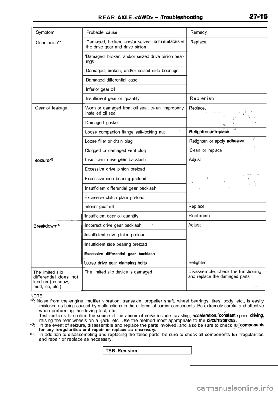
R E A R
Symptom
Gear noise**
Gear oil leakage
The limited slip
differential does not
function (on snow, mud, ice, etc.)
NOTE
Noise from the engine, muffler vibration, transaxl e, propeller shaft, wheel bearings, tires, body, etc., is easily
mistaken as being caused by malfunctions in the dif ferential carrier components. Be extremely careful and attentive
when performing the driving test, etc.
Test methods to confirm the source of the abnormal include: coasting, speed
raising the rear wheels on a -jack, etc. Use the me thod most appropriate to the
In the event of seizure, disassemble and replace the parts involved, and also be sure to check for any irregularities and repair or replace as
l 4:In addition to disassembling and replacing the failed parts, be sure to check all components forirregularities
and repair or replace as necessary.
Probable cause Remedy
Damaged, broken, and/or seized
ofReplace
the drive gear and drive pinion
‘Damaged, broken, and/or seized drive pinion bear- ings
Damaged, broken, and/or seized side bearings
Damaged differential case
Inferior gear oil
Insufficient gear oil quantity
R e p l e n i s h
Worn or damaged front oil seal, OFan improperly Replace,
installed oil seal
Damaged gasket
Loose companion flange self-locking nut
Loose filler or drain plug Retighten or apply
‘Clean or replaceClogged or damaged vent plug
Insufficient drive
backlash
Excessive drive pinion preload
Excessive side bearing preload
Insufficient differential gear backlash
Excessive clutch plate preload
Inferior gear
oil
Insufficient gear oil quantity
Incorrect drive gear backlash
Insufficient drive pinion preload
Insufficient side bearing preload
Excessive differential gear backlash
drive gear clamping bolts
The limited slip device is damaged Adjust
Replace
Replenish
Adjust
Retighten
Disassemble, check the functioning
and replace the damaged parts
TSB Revision
Page 1663 of 2103

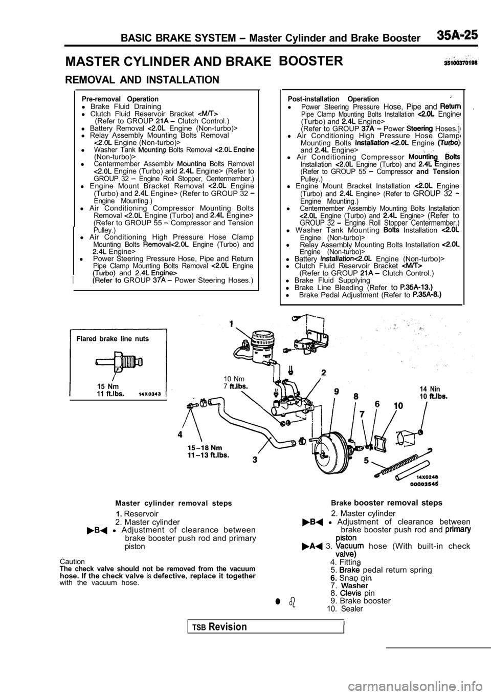
BASIC BRAKE SYSTEM Master Cylinder and Brake Booster
MASTER CYLINDER AND BRAKEBOOSTER
REMOVAL AND INSTALLATION
Pre-removal Operationl
Brake Fluid Draining
l Clutch Fluid Reservoir Bracket
(Refer to GROUP Clutch Control.)
l Battery Removal Engine (Non-turbo)>
l Relay Assembly Mounting Bolts Removal
Engine (Non-turbo)>
lWasher Tank Bolts Removal (Non-turbo)>lCentermember Assemblv Bolts Removal Engine (Turbo) arid Engine> (Refer toGROUP 32 Engine Roll Stopper, Centermember.)l Engine Mount Bracket Removal Engine
(Turbo) and Engine> (Refer to GROUP 32 Engine Mounting.)l Air Conditioning Compressor Mounting Bolts
Removal Engine (Turbo) and Engine>
(Refer to GROUP 55 Compressor and TensionPulley.)l Air Conditioning High Pressure Hose ClampMounting Bolts Engine (Turbo) and Engine>
l Power Steering Pressure Hose, Pipe and Return
Pipe Clamp Mounting Bolts Removal Engine and
I GROUP Power Steering Hoses.)
Flared brake line nuts
15 Nm11
Post-installation OperationlPower Steering Pressure Hose, Pipe and Pipe Clamp Mounting Bolts Installation Engine(Turbo) and Engine>
(Refer to GROUP Power Hoses.]
l Air Conditioning High Pressure Hose Clamp
Mounting Bolts
Engine and Engine>
l A i r C o n d i t i o n i n g C o m p r e s s o r
Installation Engine (Turbo) and ngines
(Refer to GROUP 55 Compressor and TensionPulley.)l Engine Mount Bracket Installation Engine(Turbo) and Engine> (Refer to GROUP 32 Engine Mounting.)lCentermember Assembly Mounting Bolts Installation Engine (Turbo) and Engine> (Refer toGROUP 32 Engine Roll Stopper Centermember.)l Washer Tank Mounting Installation Engine (Non-turbo)>l
Relay Assembly Mounting Bolts Installation Engine (Non-turbo)>l Battery Engine (Non-turbo)>
l Clutch Fluid Reservoir Bracket
(Refer to GROUP Clutch Control.)
l Brake Fluid Supplying
l Brake Line Bleeding (Refer to
l
Brake Pedal Adjustment (Refer to
I
10 Nm714 Nin10
Master cylinder removal steps
2. Master cylinder1.
Reservoir
l Adjustment of clearance between
brake booster push rod and primary
piston
CautionThe check valve should not be removed from the vacu umhose. If the check valve isdefective, replace it together
with the vacuum hose. Brake
booster removal steps
l Adjustment of clearance between
2. Master cylinder
brake booster push rod and
3. hose (With built-in check
4. Fittina 5.
pedal return spring
6. Snap pin
7.
8. pin
9. Brake booster
10. Sealerl b
TSBRevision
Page 1821 of 2103
STEERING Power Steering Hoses Engine (Turbo) and
POWER STEERING HOSES
ENGINE (TURBO) AND ENGINE>
REMOVAL AND INSTALLATION
Post-installation Operationl Front Bumper Installation(Refer to GROUP 51 Front Bumper.)lDrive-belt Tension Adjustment Engine (Turbo):Refer to GROUP On-vehicle Service, Engine: Refer to GROUP 11 E-On-vehicle Service.)lPower Steering Fluid Supplying l Power Steering Fluid Line Bleeding (Refer to
23-26 Nm
34 Nm
25
11 Nm 11 Nm88
118
Removal steps
1. Brake fluid reservoir assembly
2. Clutch fluid reservoir assembly
3. A/C compressor4.Oil reservoir
hose
Suction hose
8.Return hose
9.Return hose
10.Return tube11.Pressure tube 12. Pressure hose13.Return hosePressure tube
15.Return tube16. fascia bracket
17. Air guide duct
18.Cooler tube
TSB Revision