Page 1074 of 2103
TRANSAXLE
ENGINE AND ENGINE> On-vehicle Service
Standard Hydraulic Pressure
No. SelectleverpositionEngine
speed
Shift1Reducing
pressure Standard oil pressure
(psi)
24678Front
End clutchTorque
brake clutch pressurereverseconverterpressurepressure brakepressurepressure
1Idling Neutral.
2Idling gearl
(usingscan tool)
3Approx.gear2,500(64-92)
4Approx.gear 9002,500I(64-92)I
5 2Approx.gear2,500II(64-92)
6Approx.1 st gear.
1,000( 4 3 - 6 4 )
7Approx.2,500
2,240 2,240(233-319)Reverse(233-319).Approx.1,000 1,000(64-92)
1,000(145) or(145) or
more more
Standard oil pressure
NOTE must be (1.5 psi) or less.
SW-ON: Switch ON the overdrive control
SW-OFF: Switch OFF the overdrive control switch Hydraulic pressure is generated, but not the stand ard value.
TSB Revision
Page 1075 of 2103
AUTOMATIC TRANSAXLE ENGINE AND ENGINE> On-vehicle Service
Hydraulic Pressure Test Diagnosis
Case
1
Description
Nos. 2 , 3
, 5 , 6 and 7 hydraulic pressures (line pressure) are all
Reference page
2No. 1 hydraulic pressure (reducing pressure) is abn ormal.
3
4
5
No. 2 hydraulic pressure (kickdown brake apply pres sure) is abnormal.
No. 3 hydraulic pressure (kickdown brake release pressure)
and No. 4 hydraulic pressure (front clutch abnormal
No. 5 hydraulic pressure (rear clutch pressure) is abnormal
. .
No. 6 hydraulic pressure (end clutch pressure) is a bnormal
No. 7 hydraulic pressure (low-reverse brake pressur e) is abnormal
No. 8 hydraulic pressure (torque converter pressure) is
Hydraulic pressure appears in places where standard hydraulic pressure is
10 (1.5 psi) or less. .
TSB Revision
Page 1077 of 2103
AUTOMATIC TRANSAXLE
ENGINE (TURBO) AND ENGINE> Service
ringI
D-ring
Seal
O-ring
Oil seal
D-ring
0 Seal ring
RearLow-reverseI
Front clutch D-ring
A Seal ring
D-ring
brake
O-ring
TSB Revision
Page 1079 of 2103

AUTOMATIC TRANSAXLE
ENGINE (TURBO) AND ENGINE> On-vehicle Service
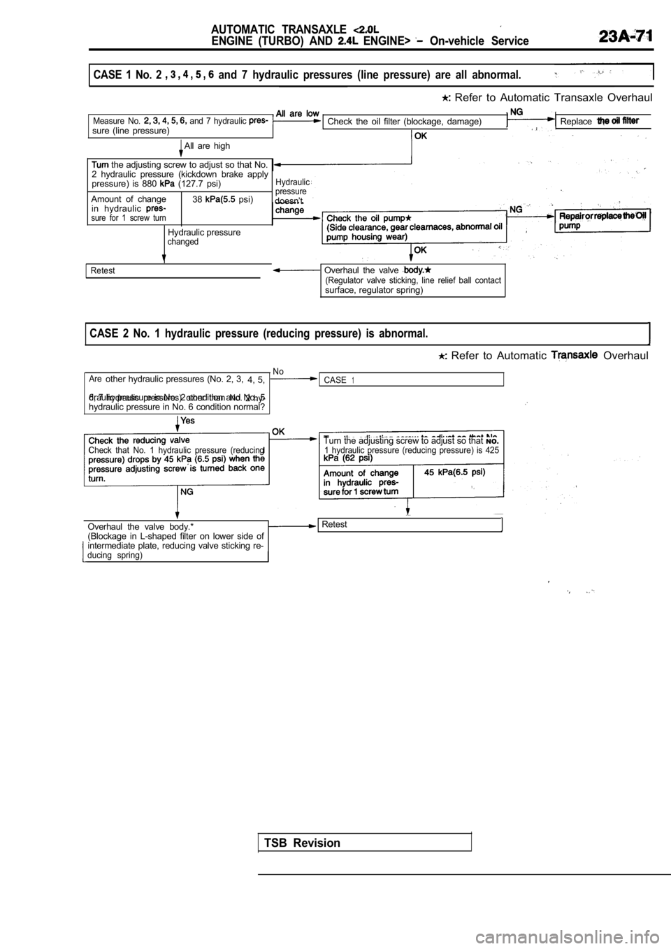
CASE 1 No. 2 and 7 hydraulic pressures (line pressure) are all abnormal.
Refer to Automatic Transaxle Overhaul
Measure No. and 7 hydraulic sure (line pressure)Check the oil filter (blockage, damage)Replace
All are high
the adjusting screw to adjust so that No.
2 hydraulic pressure (kickdown brake apply
pressure) is 880
(127.7 psi)Hydraulic
38 psi)pressureAmount of change doesn’t
in hydraulic
sure for 1 screw turn
Hydraulic pressurechanged
Retest
Overhaul the valve (Regulator valve sticking, line relief ball contactsurface, regulator spring)
CASE 2 No. 1 hydraulic pressure (reducing pressure) is abnormal.
Refer to Automatic Overhaul
No
Areother hydraulic pressures (No. 2, 3, 4, 5,CASE1
6, 7hydraulic pressures) other than No.2 hy-
draulic pressure in No. 2 condition and No. 5hydraulic pressure in No. 6 condition normal?
Check that No. 1 hydraulic pressure (reducingTurn the adjusting screw to adjust so that
NO.1 hydraulic pressure (reducing pressure) is 425
Overhaul the valve body.* Retest
(Blockage in L-shaped filter on lower side of
intermediate plate, reducing valve sticking re-
ducing spring)
TSB Revision
Page 1080 of 2103

AUTOMATIC: TRANSAXLE
ENGINE AND On-vehicle Service
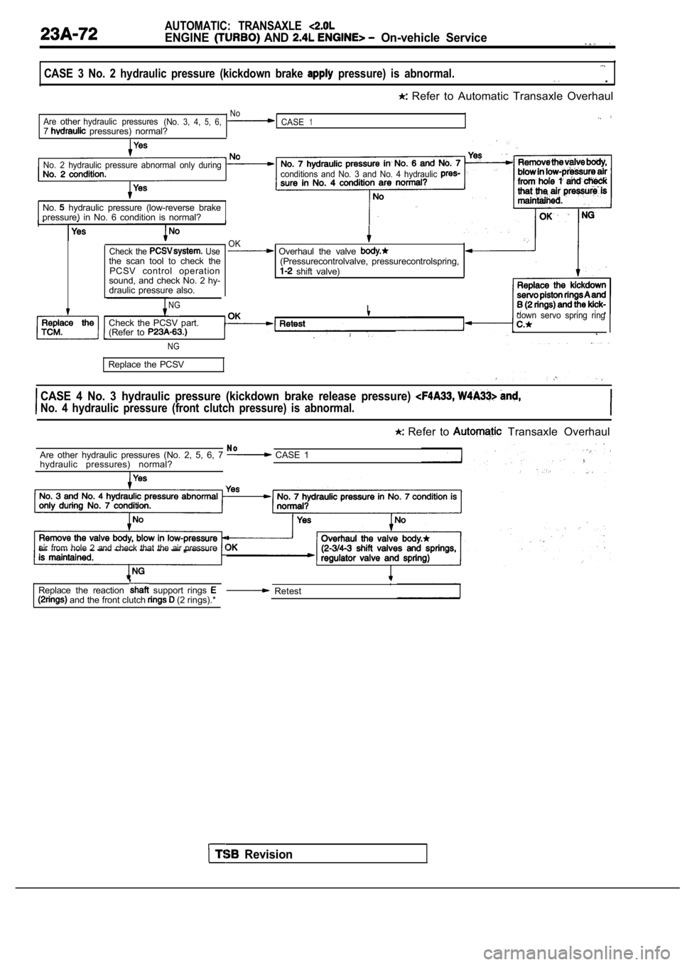
CASE 3 No. 2 hydraulic pressure (kickdown brake pressure) is abnormal. .
Refer to Automatic Transaxle Overhaul
NoAreotherhydraulic pressures(No.3, 4,5,6,CASE17 pressures) normal?
No. 2 hydraulic pressure abnormal only during
conditions and No. 3 and No. 4 hydraulic
No. hydraulic pressure (low-reverse brake
pressure) in No. 6 condition is normal?
Check the Usethe scan tool to check the
PCSV control operation
sound, and check No. 2 hy-
draulic pressure also.
NG
OK Overhaul the valve (Pressurecontrolvalve, pressurecontrolspring, shift valve)
I
Check the PCSV part.
(Refer to
,down servo spring ring
NG
Replace the PCSV
CASE 4 No. 3 hydraulic pressure (kickdown brake rel ease pressure)
No. 4 hydraulic pressure (front clutch pressure) is abnormal.
Refer to Transaxle Overhaul
N oAre other hydraulic pressures (No. 2, 5, 6, 7 CASE 1
hydraulic pressures) normal?
air from hole 2 and check that the air pressure
and the front clutch (2 rings).*
Replace the reaction support rings , Retest
Revision
Page 1092 of 2103
AUTOMATIC TRANSAXLE
ENGINE (TURBO) AND On-vehicle Service
Lock nut
SERVO ADJUSTMENT
1. Completely remove all dirt and other materials adhered
around the
servo switch.
2. Remove the snap ring.
3. Remove the
servo switch.
4. To prevent rotation of the piston, engage the
of
the special tool into the notch of the piston, and using
the adapter, secure the piston as shown to the left .
Caution
1Don’t press in the piston with the special tool.
2.When mounting the adapter on the transaxle case,
tighten it by hand. Do not overtighten.
5. Loosen the lock nut to before the V-groove of the adjusting
rod, and tighten the special tool (inner) until it contacts
the lock nut.
TSB Revision
Page 1093 of 2103
AUTOMATIC TRANSAXLE
ENGINE (TURBO) AND ENGINE> On-vehicle Service
6. Engage the special tool (outer) on the lock nut.
Rotating the outer cylinder counterclockwise and the inner
cylinder clockwise, lock the lock nut and special t ool (in-
ner).
7. Attach a torque wrench to the special tool (inne r) and
tighten to a torque of 10 Nm (7.2
and repeating
“Tighten” and “Loosen” two times then torque to 5 N m
(3.6
After that, back off the special tool (inner)
2 to
turns.
8. Engage the tool (outer) on the lock nut.
Rotating the outer cylinder clockwise and the inner cylinder
counterclockwise, unlock the lock nut and special ‘tool
(inner).
Caution
When unlocking the nut and special tool, apply equa l
force to both parts.
Revision
Page 1094 of 2103
AUTOMATIC TRANSAXLE
ENGINE (TURBO) AND ENGINE> On-vehicle Service
9. Tighten the lock nut by hand until the lock nut contacts
the piston. Then using the torque wrench, tighten t o the
specified torque.
Lock nut: (21
Caution
If it is rapidly tightened with the socket wrench o r
torque wrench, the lock nut and adjusting rod may
rotate together.
10. Remove the special tool which fastens the pisto n.
Attach the plug to the outlet of the low-reverse pressure.
TSBRevision