Page 1113 of 2103
AUTOMATIC TRANSAXLE . .
ENGINE (TURBO) AND ENGINE> Assembly
Front roll
stopper
bracket
ber
DRIVE PLATE
(1)Use a transmisslon jack to the ,,Caution
Support the transaxle
(2) Remove the connection bolts while turning
(3) Press the torque converter into the transaxle f or easier
removal.
(4) Remove the transaxle assembly mounting bolt and lower
the transaxle assembly.
,
SERVICE
TRANSAXLE ASSEMBLY
After securely inserting the torque converter the transaxle
so that the
shown in the becomes the refer-
ence value, install the assembly the engine.
value (A):
m m
12.0
ASSEMBLY
If the dimension shown in the is outside the standard
value when the weight of the engine the body, replace
the front roll stopper bracket assembly.
Standard value (A):
mm
D R I V E S H A F T
Temporarily install the drive shaft so that T.J. case of
the drive shaft is perpendicular to the
Caution
Do not damage the oil by part of the
drive shaft.
Transaxle
TSB Revision
Page 1114 of 2103

AUTOMATIC TRANSAXLE
ENGINE (TURBO) AND ENGINE> Transaxle Assembly
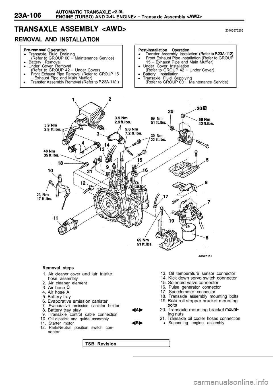
REMOVAL ANDINSTALLATION
23100570205
Operation
l Transaxle Fluid Draining
(Refer to GROUP 00
Maintenance Service)
l Battery Removal
l Under Cover Removal
(Refer to GROUP 42
Under Cover)
lFront Exhaust Pipe Removal (Refer to GROUP 15 Exhaust Pipe and Main Muffler)
l Transfer Assembly Removal (Refer to
3.92.9
Nm
Post-installation OperationlTransfer Assembly Installation l Front Exhaust Pipe Installation (Refer to GROUP
15 Exhaust Pipe and Main Muffler)
l Under Cover Installation
(Refer to GROUP 42
Under Cover)
l Battery Installation
l Transaxle Fluid Supplying
(Refer to GROUP 00
Maintenance Service)
30 Nm
22
23 17
69 Nm51
Removal steps
1. Air cleaner cover and air intake
hose assembly2. Air cleaner element
3. Air hose
4. Air hose A
5. Battery tray
6. Evaporative emission canister
7. Evaporative emission canister holder
8. Battery tray stay
9. Transaxle control cable connection
10. Oil dipstick and guide assembly
11. Starter motor
12. Park/Neutral position switch con- nector
13. Oil temperature sensor connector14. Kick down servo switch connector
15. Solenoid valve connector
16. Pulse generator connector
17. Speedometer connector
18. Transaxle assembly mounting bolts
19. roll stopper bracket mounting
20. Transaxle mounting bracket
ing nuts21. Transaxle oil cooler hoses connectionl Supporting engine assembly
TSB Revision
Page 1116 of 2103

.AUTOMATIC TRANSAXLE
ENGINE (TURBO) AND ENGINE> Transaxle Assembly
,
Cord
N i t
TSB Revision
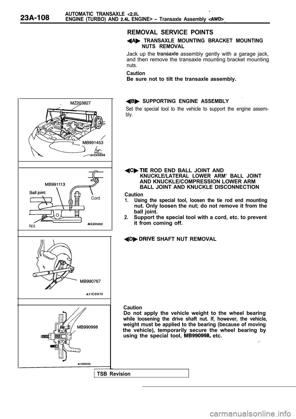
REMOVAL SERVICE POINTS
TRANSAXLE MOUNTING BRACKET MOUNTINGNUTS REMOVAL
Jack up the assembly gently with a garage jack,
and then remove the transaxle mounting bracket moun ting
nuts.
Caution
Be sure not to tilt the transaxle assembly.
SUPPORTING ENGINE ASSEMBLY
Set the special tool to the vehicle to support the engine assem-
bly.
ROD END BALL JOINT AND
KNUCKLE/LATERAL LOWER ARM’ BALL JOINT
AND KNUCKLE/COMPRESSION LOWER ARM
BALL JOINT AND KNUCKLE DISCONNECTION
Caution
1.Using the special tool, loosen the tie rod end moun ting
nut. Only loosen the nut; do not remove it from the
ball joint.
2.Support the special tool with a cord, etc. to preve nt
it from coming off.
SHAFT NUT REMOVAL
Caution
Do not apply the vehicle weight to the wheel bearin g
while loosening the drive shaft nut. If, however, the vehicle,
weight must be applied to the bearing (because of m oving
the vehicle), temporarily secure the wheel bearing by
using the special tool,
etc.
Page 1118 of 2103

AUTOMATIC TRANSAXLE
ENGINE (TURBO) AND ENGINE> Transaxle Assembly
Front roll
I - -
stopper
bracket
Centermember
Washer
(2) Remove the connection bolts while turning the crankshaft.
(3) Press the torque converter into the transaxle for easier
removal.
(4) Remove the transaxle assembly mounting bolt and lower
the transaxle assembly.
INSTALLATION SERVICE POINTS
TRANSAXLE ASSEMBLY INSTALLATION
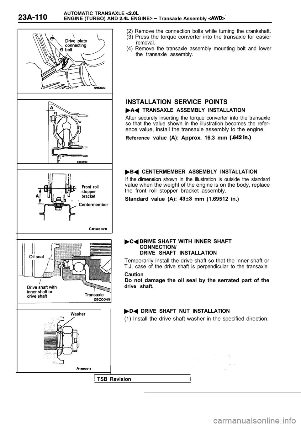
After securely inserting the torque converter into the transaxle
so that the value shown in the illustration becomes the refer-
ence value, install the transaxle assembly to the engine.
Reference value (A): Approx. 16.3 mm
CENTERMEMBER ASSEMBLY INSTALLATION
If the shown in the illustration is outside the standard
value when the weight of the engine is on the body, replace
the front roll stopper bracket assembly.
Standard value (A):
mm (1.69512 in.)
SHAFT WITH INNER SHAFT
CONNECTION/ DRIVE SHAFT INSTALLATION
Temporarily install the drive shaft so that the inn er shaft or
T.J. case of the drive shaft is perpendicular to th e transaxle.
Caution
Do not damage the oil seal by the serrated part of the
drive shaft.
DRIVE SHAFT NUT INSTALLATION
(1) Install the drive shaft washer in the specified direction.
TSB RevisionI
Page 1120 of 2103
AUTOMATIC TRANSAXLE ENGINE (TURBO) AND Transfer Assembly
REMOVAL AND INSTALLATION
Pre-removal and Post-installation OperationlTransfer Oil Draining and Supplying
(Refer to GROUP 00 Maintenance Service)
lFront Exhaust Pipe Removal and installation (Referto GROUP 42 Exhaust Pipe and Main Muffler.)
Gear oil:
classification SAE
1. Transfer assembly
69 Nm51
REMOVAL SERVICE POINT
ASSEMBLY REMOVAL
Caution
1. Do not damage the oil seal lip of the transfer.
2. Use the special tool to cover the transfer case to
prevent oil from gushing out or foreign materials from
getting into the transfer case.
Revision
Page 1132 of 2103
AUTOMATIC TRANSAXLE
ENGINE Troubleshooting
SERVICE DATA REFERENCE TABLE
Data No. Check itemDisplay
00 Throttle position sensor
01Transaxle range sensor 41
02Start or run position volt
03Transaxle range sensor 43
04 Switched battery volt
20 pressure switch
ON/OFF
212-4 pressureswitch
ON/OFF
22ODpressureswitch
ON/OFF
23 Overdrive lockout switch
ON/OFF
24Transaxle range sensor 1ON/OFF
25 Transaxle range sensor 2
ON/OFF
26Transaxle range sensor 43ON/OFF
27 Transaxle range sensor 41
ON/OFF
43 Engine speed
44Transaxle input speed
45Transaxle output speed
46Shift lever position information and controller lim
p-in status
Status
47Throttle position
48Transaxle shift schedule
Status
Partial/full lock status
58Shift code Status
59
60
61
Pressure switch error counter Counts
Speed/ratio error counter Counts
Speed/ratio error 1 second counter Counts
TSB Revision
Page 1167 of 2103

AUTOMATIC TRANSAXLE
ENGINE (NON-TURBO)>
.
to GROU’P 00
RefertoGROUP 00 Maintenance Service.
TCM RESETTING
(1) Disconnect the negative battery cable from the
before replacing the transaxle out overhaul.
(2) After work has been completed, check
trouble codes (DTC). If DTC 12 (“Battery power was
disconnected since last power has been
generated, this DTC must be cleared. Furthermore, select “Special function” on the scan tool
and then set the scan tool to Quick Learn mode (car ry
out this operation from the scan tool screen). Then input
the clutch volume index into the
PINION FACTOR WRITING PROCEDURE
REPLACEMENT OR TIRE SIZE
NOTE
With transmissions, the TCM uses the rotation speed
of the transaxle output shaft to calculate the vehicle speed
and cumulative distance
Because of this, it is
necessary to input (or update) the tire size coeffi cient into
the TCM memory after the TCM has been replaced or t he
tire size has been changed.
(1) Select “Special function” on the scan
and then set
the scan tool to Pinion Factor mode (carry out this operation from the scan tool screen). Then input (o r
update) the tire size coefficient the TCM memory.
Note that new
do not a tire size
already input.
TSB Revision
Page 1168 of 2103
AUTOMATIC TRANSAXLE
ENGINE (NON-TURBO)> On-vehicle Service
TRANSAXLE RANGE SENSOR CONTINUITY
CHECK
(1) Disconnect the transaxle range sensor connector.
(2) Check the continuity between sensor terminals a nd body
ground (and terminals while shifting the
lever at each position. The continuity between sensor
terminals and body ground (and terminals
should
be as shown in the table below.
LeverTerminal No. Body
,
TSB Revision
(3) If there is a defect, replace the transaxle ran ge sensor.
OIL TEMPERATURE SENSOR CONTINUITY
CHECK
(1) Disconnect thetransaxle range sensor connector.
(2) Measure the resistance between terminals 2-3 an d check
that the values are as shown in the table below.
Oil temperature Resistance value
(32)29.33 35.99
100 (212)640720
(3) If the values are outside the standard values, replace
the transaxle range sensor.