Page 1191 of 2103
AUTOMATIC TRANSAXLE
ENGINE. On-vehicle Service
Converter Clutch ONOVERDRIVE
- -
CHAIN LUBE
O N
S W
1
TSB Revision
Page 1192 of 2103
AUTOMATIC TRANSAXLE
ENGINE On-vehicle Service
Refer to
Refer to
Refer to ,
TSB Revision
Page 1196 of 2103

AUTOMATIC TRANSAXLE
ENGINE Transaxle Control
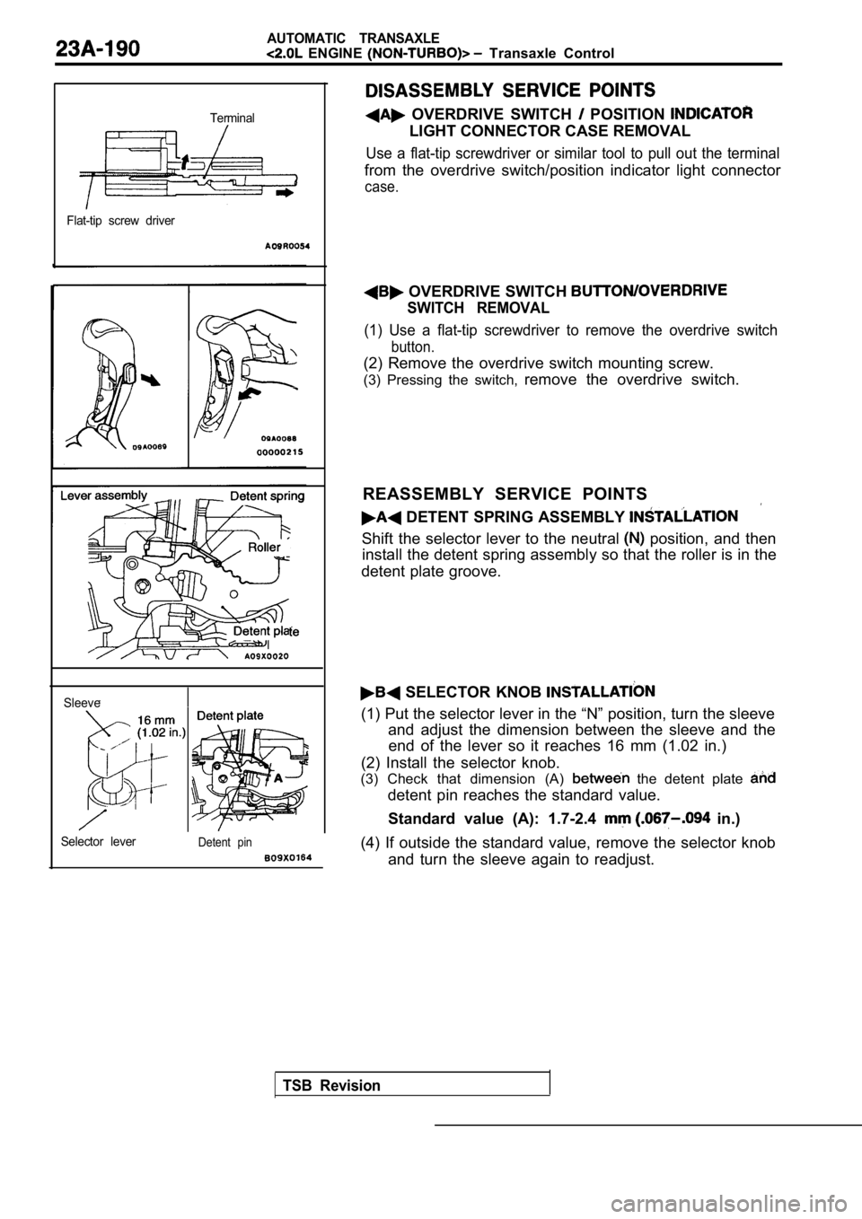
Terminal
Flat-tip screw driver
TSB Revision
Sleeve
Selector lever
Detent pin
OVERDRIVE SWITCH POSITION
LIGHT CONNECTOR CASE REMOVAL
Use a flat-tip screwdriver or similar tool to pull out the terminal
from the overdrive switch/position indicator light connector
case.
OVERDRIVE SWITCH
SWITCH REMOVAL
(1) Use a flat-tip screwdriver to remove the overdr ive switch
button.
(2) Remove the overdrive switch mounting screw.
(3) Pressing the switch, remove the overdrive switch.
REASSEMBLY SERVICE POINTS
DETENT SPRING ASSEMBLY
Shift the selector lever to the neutral position, and then
install the detent spring assembly so that the roll er is in the
detent plate groove.
SELECTOR KNOB
(1) Put the selector lever in the “N” position, tur n the sleeve
and adjust the dimension between the sleeve and the end of the lever so it reaches 16 mm (1.02 in.)
(2) Install the selector knob.
(3) Check that dimension (A)
the detent plate
detent pin reaches the standard value.
Standard value (A): 1.7-2.4
in.)
(4) If outside the standard value, remove the selec tor knob
and turn the sleeve again to readjust.
Page 1200 of 2103

AUTOMATIC TRANSAXLE
ENGINE (NON-TURBO)> Transaxle Assembly
TRANSAXLE ASSEMBLY
l Transaxle Fluid Draining
l Transaxle Fluid Draining
(Refer to GROUP 00 Maintenance service)
(Refer to GROUP 00 Maintenance service)
l Battery Removal
l Battery Removal
l Under Cover Removal
l Under Cover Removal
(Refer to GROUP 42
Under Cover)
(Refer to GROUP 42 Under Cover)
7454
Post-installation Operationl Under Cover Installation
(Refer to GROUP Under Cover)
l Battery Installation
l Transaxle Fluid Supplying
(Refer to GROUP 00
Maintenance Service)
l Selector Lever Operation Check
9.2
6
5140
69 Nm51 I
42
51
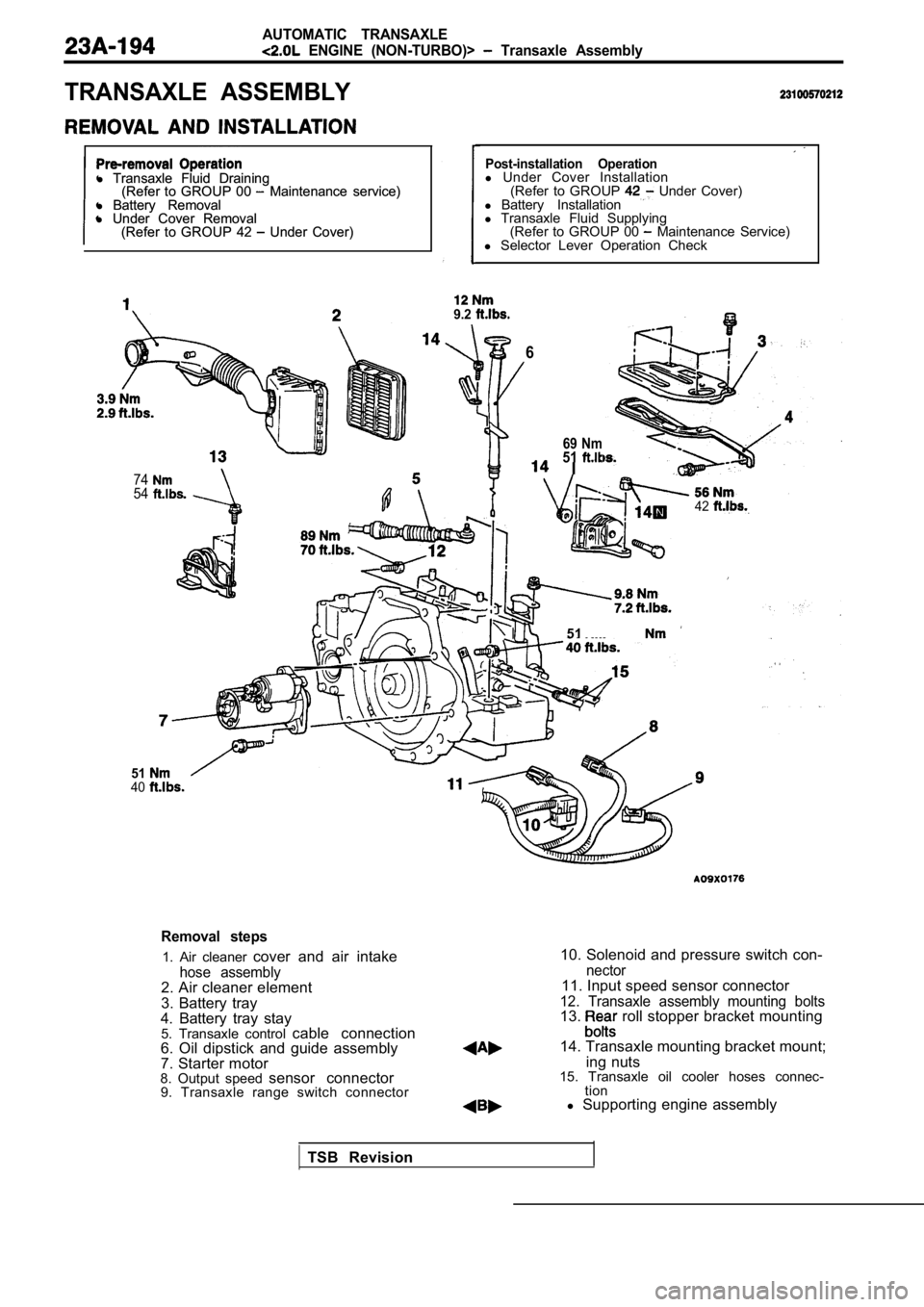
Removal steps
1. Air cleaner cover and air intake
hose assembly2. Air cleaner element
3. Battery tray
4. Battery tray stay 5. Transaxle control cable connection
6. Oil dipstick and guide assembly
7. Starter motor
8. Output speed sensor connector
9. Transaxle range switch connector
10. Solenoid and pressure switch con-
nector11. Input speed sensor connector
12. Transaxle assembly mounting bolts13. roll stopper bracket mounting
14. Transaxle mounting bracket mount; ing nuts
15. Transaxle oil cooler hoses connec- tion
l Supporting engine assembly
TSB Revision
Page 1202 of 2103

AUTOMATIC TRANSAXLE
ENGINE (NON-TURBO)> Transaxle Assembly
Nut2
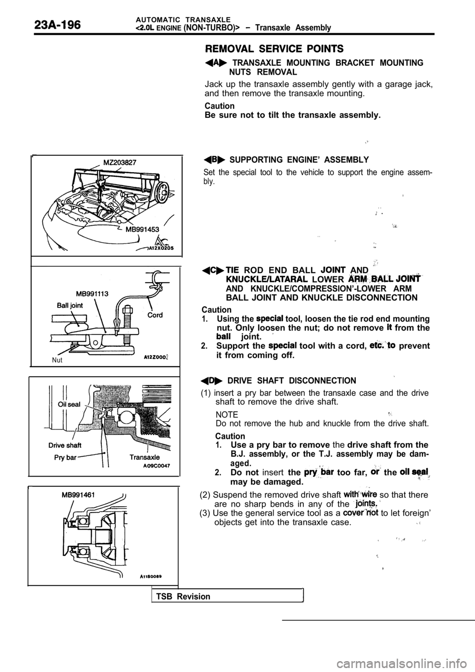
TRANSAXLE MOUNTING BRACKET MOUNTINGNUTS REMOVAL
Jack up the transaxle assembly gently with a garage jack,
and then remove the transaxle mounting.
Caution
Be sure not to tilt the transaxle assembly.
SUPPORTING ENGINE’ ASSEMBLY
Set the special tool to the vehicle to support the engine assem-
bly.
,
. . .
. .
ROD END BALL AND
LOWER
AND KNUCKLE/COMPRESSION’-LOWER ARM
BALL JOINT AND KNUCKLE DISCONNECTION
Caution
1.Using the tool, loosen the tie rod end mounting
nut. Only loosen the nut; do not remove from the
joint.
2.Support the tool with a cord, prevent
it from coming off.
DRIVE SHAFT DISCONNECTION
(1) insert a pry bar between the transaxle case and the drive
shaft to remove the drive shaft.
NOTE
Do not remove the hub and knuckle from the drive sh aft.
Caution
1.Use a pry bar to remove thedrive shaft from the
B.J. assembly, or the T.J. assembly may be dam-
aged.
2.
Do not insertthe too far, the
may be damaged.
(2) Suspend the removed drive shaft
so that there
are no sharp bends in any of the
(3) Use the general service tool as a to let foreign’
objects get into the transaxle case.
,
TSB Revision
Page 1207 of 2103

.
,
GEAR AND TRANSFER DRIVE
GEAR SET . . . .
. . . . . . . . . . . . . . . . . . . . . . . .62
DIFFERENTIAL
. . . . . . . . . . . . . . . . . . . . . . . . . . . .64
DRIVE SHAFT OIL SEAL . . . . . . . . . . . . . . . . . .70
END CLUTCH. . . . . . . . . . . . . . . . . . . . . . . . . . . . .57
FRONT CLUTCH. . . . . . . . . . . . . . . . . . . . . . . . . .51
GENERAL INFORMATION. . . . . . . . . . . . . . . . . .2
SERVO. . . . . . . . . . . . . . . . . . . . . . .68
LOW-REVERSE BRAKE. . . . . . . . . . . . . . . . . .67
OIL PUMP
. . . . . . . . . . . . . . . . . . . . . . . . . . . . . . . .49
PLANETARY GEAR
. . . . . . . . . . . . . . . . . . . . . . .59
REAR CLUTCH. . . . . . . . . . . . . . . . . . . . . . . . . . .54
SPECIAL. . . . . ... . . . . . . . . . . . .. . ...... ....
SPECIFICATIONS. . . . . . . . . . . . . .. .. . . ........ .
Gear Ratio Table. . . . . . . . . . . . . . . . . . . . . . . . . . . .
Pressure Plates, Snap Rings and
Spacers for Adjustment. . . . . . . . . . . . . . . . . . . . . .6
Service Specifications. . . . . . . . . . . . . . . . . . . . . . . .5
Torque Specifications. . . . . . . . . . . . . . . . . . . . . . . . .9
Transaxle Model Table. . . . . . . . . . . . . . . . . . . . . . .5
Valve Body Spring Identification . . . . . . . . . . . . . . .6
SPEEDOMETER GEAR. . . . . . . . . . . . . . . . . . .
TRANSAXLE. . . . . . . . . . . . . . . . . . . . . . . . . . . . . .14
TRANSFER DRIVEN GEAR . . . . . . . . . . . . . . .
TRANSFER SHAFT
. . . . . . . . . . . . . . . . . . . . . . .71
VALVE BODY. . . . . . . . . . . . . . . . . . . . . . . . . . . . .73
Page 1217 of 2103
AUTOMATIC TRANSAXLE
OVERHAUL Special Tools,
Super-session ,
Alignment of oil ‘pump housing and reaction
s h a f t
Tool Tool numberand
name
Guide pin
Spring
compressor
Spring
compressor
servo
set
-01
adapter
puller
ringnstaller
10998812
nstaller cap service
Use
Disassembly clutch
installation of servo
Removal and installation of transfer
shaft
of bearing
Assembly of the end clutch
of
. .
with installer and installer adapter
TSB Revision
Page 1255 of 2103
A U T O M A T I C .
O V E R H A U L
OIL PUMP
DISASSEMBLY AND REASSEMBLY
.
.
2 Nm
Disassembly steps
1.O-ring 2. Reaction shaft support3.Steel ball
4. Drive gear 5. Driven gear6.Seal ring
7. Oil seal6. Oil pump housing
9.Snap ring10.Oil seal
.
,.
DISASSEMBLY SERVICE POINT
GEAR DRIVEN GEAR REMOVAL
Make reassembly alignment marks on the drive and driven
gears.
Revision