Page 1095 of 2103
AUTOMATIC TRANSAXLE
ENGINE (TURBO) AND ENGINE> On-vehicle Service
23100170047
1. Drain out the automatic transmission fluid.
2. Remove the oil pan.
3. Remove the oil filter.
4. Remove the oil temperature sensor.
5.Press the solenoid valve harness grommet and connec tor
into the transaxle case.
6.Press the catches of the solenoid valve harness grommets
and pass the connector through the case hole.
7.Remove the valve body assembly. The manual
come out, so be careful not to drop it.
valve can
Page 1096 of 2103
AUTOMATIC TRANSAXLE
ENGINE (TURBO) AND ENGINE> On-vehicle Service
Adjustment screw
I
8. Turn the adjustment screw of the regulator valve and
adjust so that the line pressure (kickdown brake pressure)
becomes the standard value.
When the adjustment screw is turned clockwise, the line
pressure decreases; when it is turned to counterclockwise,
it increases.
Standard value: psi)
Oil pressure change for each turn of adjustment
screw: 38
(5.5 psi)
9. Check that the O-ring is installed on the upper surface
of the valve body at the place shown in the figure.
10. Replace the O-ring of the solenoid valve harnes s grommet
with a new one.
11. Pass the solenoid valve connector through the i nside
of the hole in the case.
T S B R e v i s i o n
Page 1100 of 2103
AUTOMATIC TRANSAXLE
ENGINE (TURBO) AND ENGINE> On-vehicle Service‘
ACCSHIFT LOCK MECHANISM
1.
2.
3.
4.
Push button
Push button ACC
ACCI
TSB Revision Check that, under the following conditions, the sel
ector
lever cannot be moved from the position to any other
position.
Ignition keyposition: “ACC”
Brake pedal: Not depressed
Button: Pressed
Check that, under the following conditions, the sel ector
lever can be moved smoothly from the
position to
any other position.
Ignition keyposition: “ACC”
Brake pedal: Depressed
Button: Pressed
I.
Check that, under the following conditions, the sel ector
lever can be moved smoothly from the
position to
the “P” position.
Ignition key position: “ACC”
Brake pedal: Released
Button: Pressed
If a malfunction is discovered when following the a bove
checking procedures, either adjust or check the shi ft lock
cable mechanism. (Refer to P.
Page 1103 of 2103
AUTOMATIC TRANSAXLE
ENGINE (TURBO) AND
SELECTOR LEVER ASSEMBLY
DISASSEMBLY AND REASSEMBLY
arrow-located places)
Disassembly steps
11 Nm8.3
1. Overdrive switch position indicator12. Position indicator light assembly
light connector case
2.Cover
3. Selector knob4. Overdrive switch button5. Overdrive switch6.Pin
13.Sleeve
14.Bolt15.Lever assembly
16. Detent spring assembly17.Bushing18.Pipe19.Cotter pin20.Washer21.Lock cam22.Bracket assembly
91.5
2Nm
7. Push button8. Spring9. Indicator panel upper10. Slider11. Indicator panel lower
Terminal
Flat-tip screw driver
TSB Revision
DISASSEMBLY SERVICE POINTS
OVERDRIVE SWITCH POSITION INDICATOR
LIGHT CONNECTOR CASE REMOVAL
Use a flat-tip screwdriver or similar tool to pull out the terminal
from the overdrive switch/position indicator light connector
case.
Page 1104 of 2103

AUTOMATIC TRANSAXLE
ENGINE (TURBO) AND ENGINE> Transaxle Control
-ever
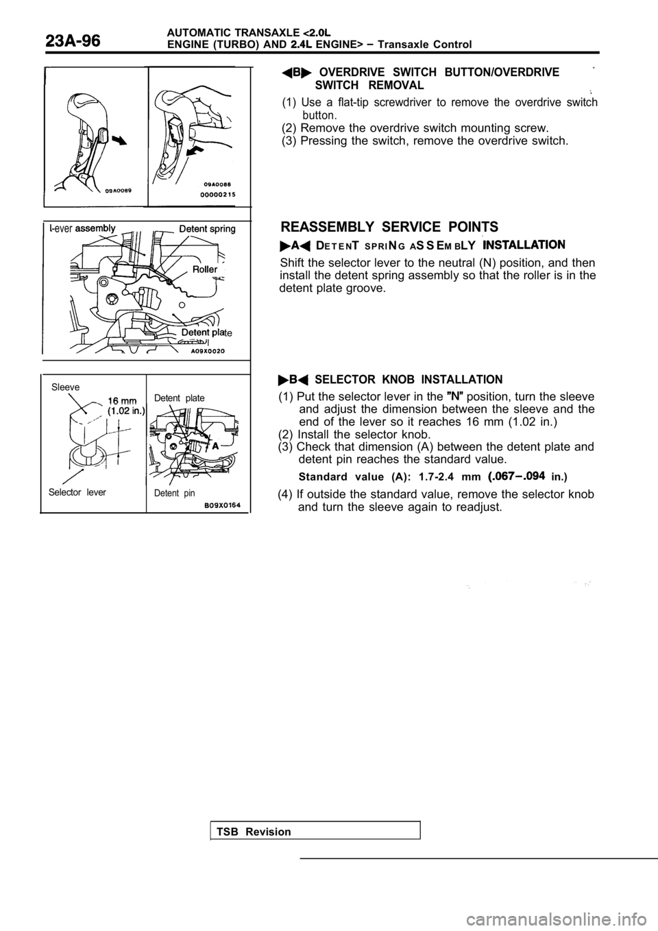
te
SleeveDetent plate
Selector lever
Detent pin
TSB Revision
OVERDRIVE SWITCH BUTTON/OVERDRIVE
SWITCH REMOVAL
(1) Use a flat-tip screwdriver to remove the overdr ive switch
button.
(2) Remove the overdrive switch mounting screw.
(3) Pressing the switch, remove the overdrive switch.
REASSEMBLY SERVICE POINTS
DE T E N TS P R I NG A S S E M BLY
Shift the selector lever to the neutral (N) positio n, and then
install the detent spring assembly so that the roll er is in the
detent plate groove.
SELECTOR KNOB INSTALLATION
(1) Put the selector lever in the position, turn the sleeve
and adjust the dimension between the sleeve and the
end of the lever so it reaches 16 mm (1.02 in.)
(2) Install the selector knob.
(3) Check that dimension (A) between the detent pla te and
detent pin reaches the standard value.
Standard value (A): 1.7-2.4 mm
in.)
(4) If outside the standard value, remove the selec tor knob
and turn the sleeve again to readjust.
Page 1108 of 2103

AUTOMATIC TRANSAXLE
ENGINE (TURBO) AND ENGINE> Transaxle Assembly
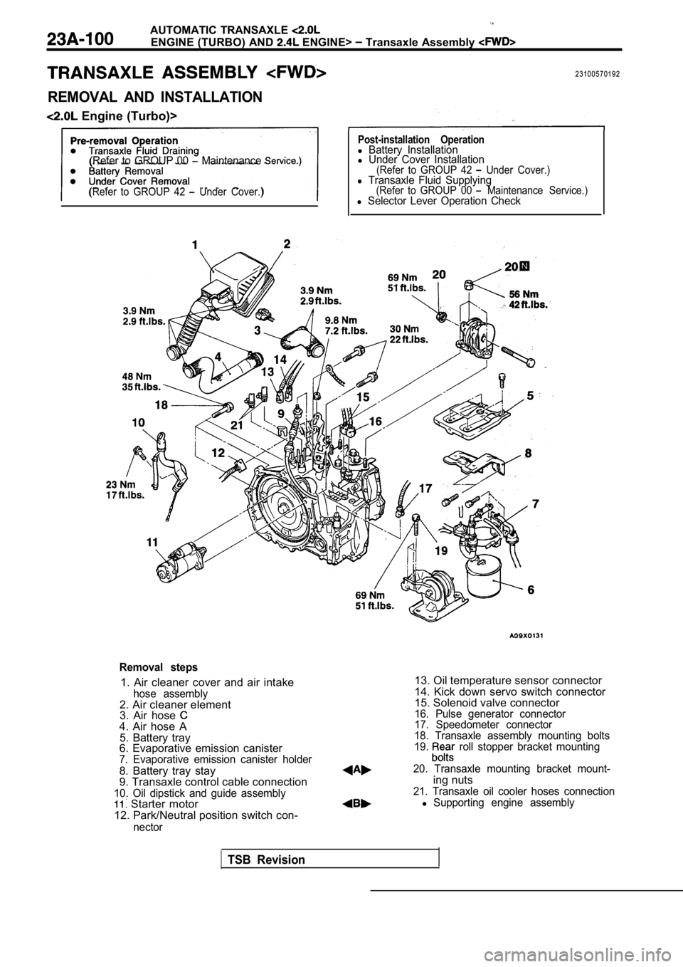
23100570192
REMOVAL AND INSTALLATION
Engine (Turbo)>
(Refer to GROUP 00 Maintenance
(Refer to GROUP 42 Under Cover.)
Post-installation Operationl Battery Installationl Under Cover Installation(Refer to GROUP 42 Under Cover.)l Transaxle Fluid Supplying(Refer to GROUP 00 Maintenance Service.)l Selector Lever Operation Check
Removal steps
1. Air cleaner cover and air intakehose assembly2. Air cleaner element
3. Air hose
4. Air hose A5. Battery tray
6. Evaporative emission canister
7. Evaporative emission canister holder
8. Battery tray stay
9. Transaxle control cable connection
10. Oil dipstick and guide assembly Starter motor
12. Park/Neutral position switch con-
nector
13. Oil temperature sensor connector
14. Kick down servo switch connector
15. Solenoid valve connector
16. Pulse generator connector
17. Speedometer connector
18. Transaxle assembly mounting bolts
19.
roll stopper bracket mounting
20. Transaxle mounting bracket mount-
ing nuts21. Transaxle oil cooler hoses connectionl Supporting engine assembly
TSB Revision
Page 1110 of 2103

AUTOMATICTRANSAXLE
ENGINE (TURBO) AND ENGINE> Transaxle Assembly
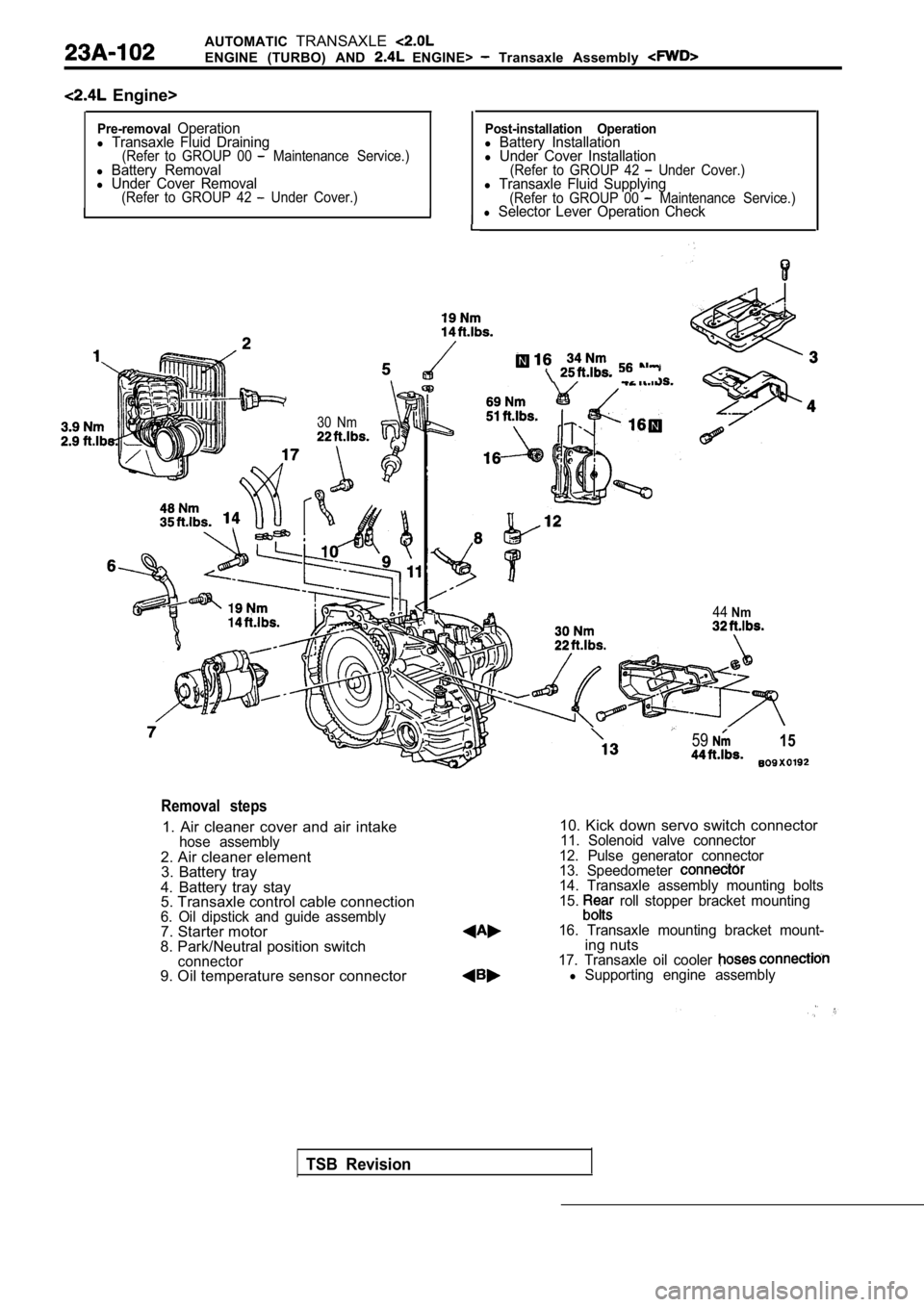
Engine>
Pre-removalOperationl Transaxle Fluid Draining(Refer to GROUP 00 Maintenance Service.)l Battery Removall Under Cover Removal(Refer to GROUP 42 Under Cover.)I
I
I
Post-installation Operationl Battery Installationl Under Cover Installation(Refer to GROUP 42 Under Cover.)l Transaxle Fluid Supplying(Refer to GROUP 00 Maintenance Service.)l Selector Lever Operation Check
30 Nm
5915
44Nm
TSB Revision
Removal steps
1. Air cleaner cover and air intakehose assembly2. Air cleaner element
3. Battery tray
4. Battery tray stay
5. Transaxle control cable connection
6. Oil dipstick and guide assembly7. Starter motor
8. Park/Neutral position switch
connector9. Oil temperature sensor connector
10. Kick down servo switch connector11. Solenoid valve connector
12. Pulse generator connector
13. Speedometer
14. Transaxle assembly mounting bolts
15. roll stopper bracket mounting
16. Transaxle mounting bracket mount-
ing nuts17. Transaxle oil cooler l Supporting engine assembly
Page 1112 of 2103

AUTOMATIC TRANSAXLE
ENGINE AND ENGINE> Transaxle Assemblv
,
Nut
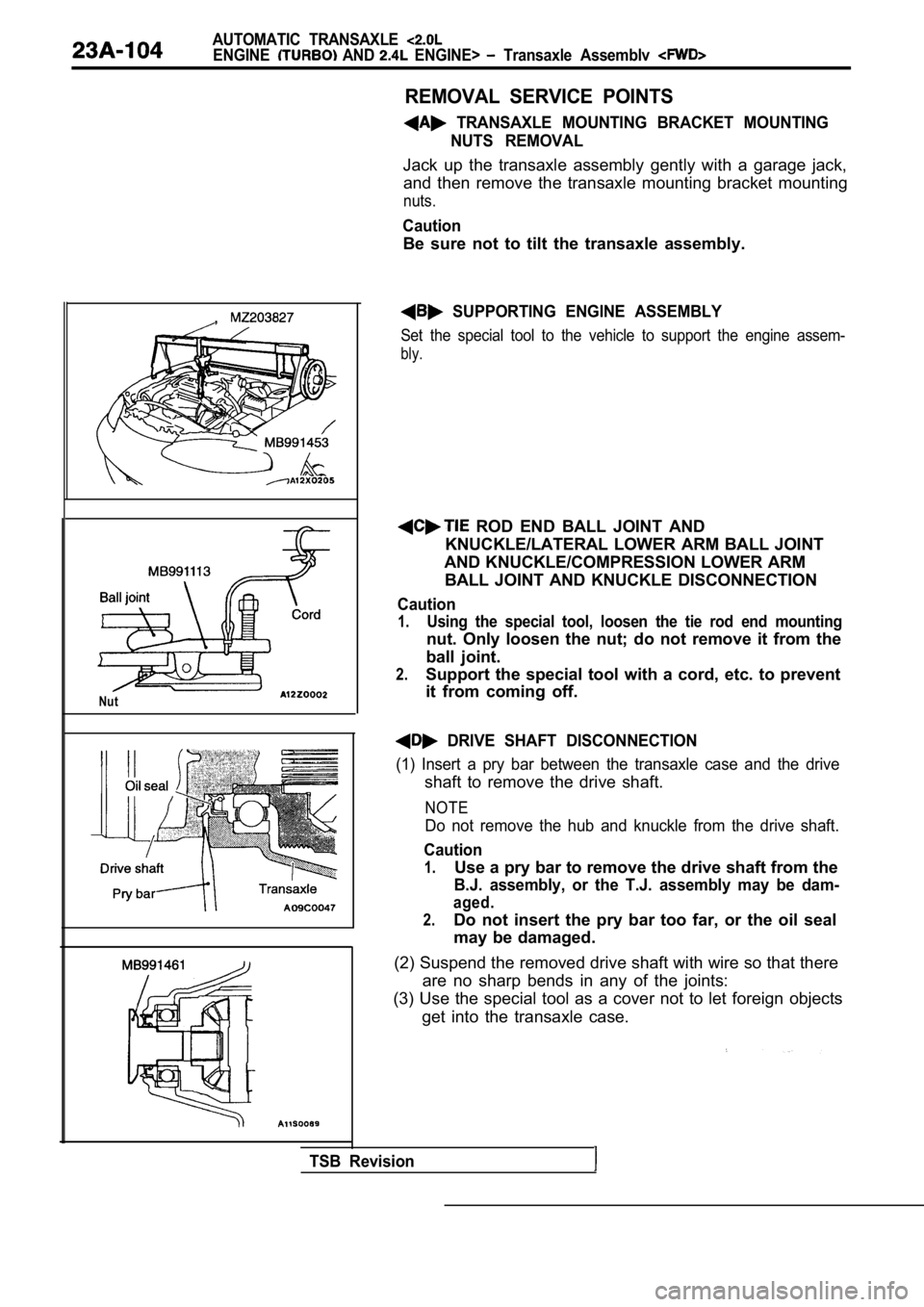
REMOVAL SERVICE POINTS
TRANSAXLE MOUNTING BRACKET MOUNTINGNUTS REMOVAL
Jack up the transaxle assembly gently with a garage jack,
and then remove the transaxle mounting bracket moun ting
nuts.
Caution
Be sure not to tilt the transaxle assembly.
SUPPORTING ENGINE ASSEMBLY
Set the special tool to the vehicle to support the engine assem-
bly.
ROD END BALL JOINT AND
KNUCKLE/LATERAL LOWER ARM BALL JOINT
AND KNUCKLE/COMPRESSION LOWER ARM BALL JOINT AND KNUCKLE DISCONNECTION
Caution
1.Using the special tool, loosen the tie rod end moun ting
nut. Only loosen the nut; do not remove it from the
ball joint.
2.Support the special tool with a cord, etc. to preve nt
it from coming off.
DRIVE SHAFT DISCONNECTION
(1) Insert a pry bar between the transaxle case and the drive
shaft to remove the drive shaft.
NOTE
Do not remove the hub and knuckle from the drive sh aft.
Caution
1.Use a pry bar to remove the drive shaft from the
B.J. assembly, or the T.J. assembly may be dam-
aged.
2.Do not insert the pry bar too far, or the oil seal
may be damaged.
(2) Suspend the removed drive shaft with wire so th at there
are no sharp bends in any of the joints:
(3) Use the special tool as a cover not to let fore ign objects
get into the transaxle case.
TSB Revision