Page 966 of 2103
MANUAL TRANSAXLE OVERHAUL ,
Transfer Case Adapter
TRANSFER CASE ADAPTER
DISASSEMBLY AND REASSEMBLY
8
Disassembly steps
1. Lock nut2. Driven bevel gear assembly
3. Taper roller bearing 4. Spacer
22210133
5. Collar6. Outer race
7. Outer race
6. Transfer case assembly
DISASSEMBLY SERVICE POINTS
LOCK NUT REMOVAL
(1) Unlock the lock nut. (Straighten the bent nut.)
TSB Revision
Page 968 of 2103
MANUAL TRANSAXLE OVERHAULDrive .
DRIVE BEVEL GEAR
DISASSEMBLY AND REASSEMBLY
Disassembly steps
1. Taper roller bearing 2. Taper roller bearing 3. Drive bevel gear
4. Drive bevel gear shaft
22210142
DISASSEMBLY SERVICE POINTS‘.
ROLLER BEARING REMOVAL
Page 969 of 2103
MANUAL TRANSAXLE OVERHAUL
Drive Bevel Gear
DRIVE
,
REASSEMBLY SERVICE
TRANSFER DRIVE BEVEL GEAR INSTALLATION
Install the drive bevel gear and drive bevel gear s haft with
the mating marks aligned.
TAPER ROLLER BEARING INSTALLATION
TSBI
Page 970 of 2103
MANUAL TRANSAXLE OVERHAUL
Driven Bevel .. .
DISASSEMBLY AND REASSEMBLY
. .
,
Lubricate all internalparts with engine oil
during reassembly.
Disassembly steps
1. Driven bevel gear
2. Taper roller bearing
14
3
D I S A S S E M B L Y
ROLLER BEARING
REASSEMBLY SERVICE POINT
TAPER ROLLER BEARING INSTALLATION
TSB Revision.
Page 971 of 2103
CONTENTS
CASE DISASSEMBLY . . . . . . . . . . . . . . . . . . . . 8
CASE REASSEMBLY. . . . . . . . . . . . . . . . . . .31
DIFFERENTIAL BEARING PRELOAD
ADJUSTMENT. . . . . . . . . . . . . . . . . . . . . . . . . .35
DIFFERENTIAL’ OVERHAUL. . . . . . . . . . . . .17
GEAR CASE OVERHAUL . . . . . . . . . . . . . . . 22
GENERAL INFORMATION
. . . . . . . . . . . . . . . .2
GENERAL SPECIFICATIONS. . . . . . . . . . . . .4
INPUT SHAFT DISASSEMBLY. . . . . . . . . . .13
INPUT SHAFT REASSEMBLY. . . . . . . . . . .28OUTPUT GEAR DISASSEMBLY
. . . . . . . . .16
SEALANTS. . . . . . . . . . . . . . . . . . . . . . . . . . . . . .4
SERVICE SPECIFICATIONS. . . . . . . . . . . . . .4
SHIFTER RAILS OVERHAUL
. . . . . . . . . . . .22
SPECIAL TOOLS. . . . . . . . . . . . . . . . . . . . . . . .5
SPECIFICATIONS. . . . . . . . . . . . . . . . . . . . . . . .4
SYNCHRONIZER OVERHAUL. . . . . . . . . . .20
TORQUE SPECIFICATIONS. . . . . . . . . . . . . .4
TRANSAXLE CLEANING AND CHECK .
Page 972 of 2103
MANUAL TRANSAXLE General Information
22210010018
The transaxle internal components can only
be serviced by separating the gear case from the
case. The transaxle output shaft is
as a unit, no, disassembly and reassembly
is possible. Damage to the transaxle may results.
TSB Revision
Page 974 of 2103
MANUAL TRANSAXLE Specifications
SPECIFICATIONS
GENERAL SPECIFICATIONS
Model
Applicable engine
Gear ratio1
Reverse
Final gear ratio
Speedometer gear ratio (driven/drive)
SERVICE SPECIFICATIONS
Differential side gear end playmm (in.)
Differential case preload mm (in.)
Specifications
-1
floor shift floor shift
3.54
3.54
2.132.13
1.36 1.36
1 . 0 3
3.94 ,
3.55
Specifications,
. 0.18
TORQUE SPECIFICATIONS22210040017
ItemsN m
Back-up light switch 2418
Differential ring boltgear81
End cover bolt2921
Output bearing race retainingstrap9.6
R e v e r s e i d l e r b o l tgear2619
Reverse fork bracket bolt119.6
Shift cable bracket-transaxle28 20
Transaxle case clutch housing bolt2921
SEALANTS22210050010
ItemsSpecified sealant
End cover and bolts
Clutch housing to transaxle case
Loctite 18718 or equivalent
Loctite 51817 or equivalent
As required
As required
Clutch housing to transaxle case bolts Loctite 51817 or equivalent
As requiredI
TSB Revision
Page 992 of 2103

Shifter Rails Overhaul/
MANUAL
SHIFTER
Disassemble the transaxle case using the procedures’
provided in this group.
(2) Remove shifter rails from the
(3) To service the shift rail, remove the retaining
the reverse shift lever arm. Remove the
“shift fork
roll pin and remove the
shift fork.
Remove the shift lug roll pin and remove the shift lug.’
Replace parts as necessary.
(4) To service the
shift rail, remove the roll pin retaining’
the
shift fork. Remove the shift fork.,, Remove the
shift lug roll pin and remove shift lug. Replace pa rts as,
necessary.
(5) To service the shift rail, remove roll pin retaining,
the shift fork. Remove the shift replace parts
as necessary.
GEAR CASE
The sealant used to seal the transaxle case halves is Loctite
51817 or equivalent. The sealant used for the bearing end
plate cover is Loctite
or equivalent.
The components that are left in the gear cases when the
gear train is pulled out are the:
Axle shaft seals
Output bearing race and retainer Input bearing and sleeve
Differential bearing cones
Shifter rail bushings ,
Shifter shafts
Shifter shaft seals
Shifter shaft bushings
Rear bearing oil feed trough
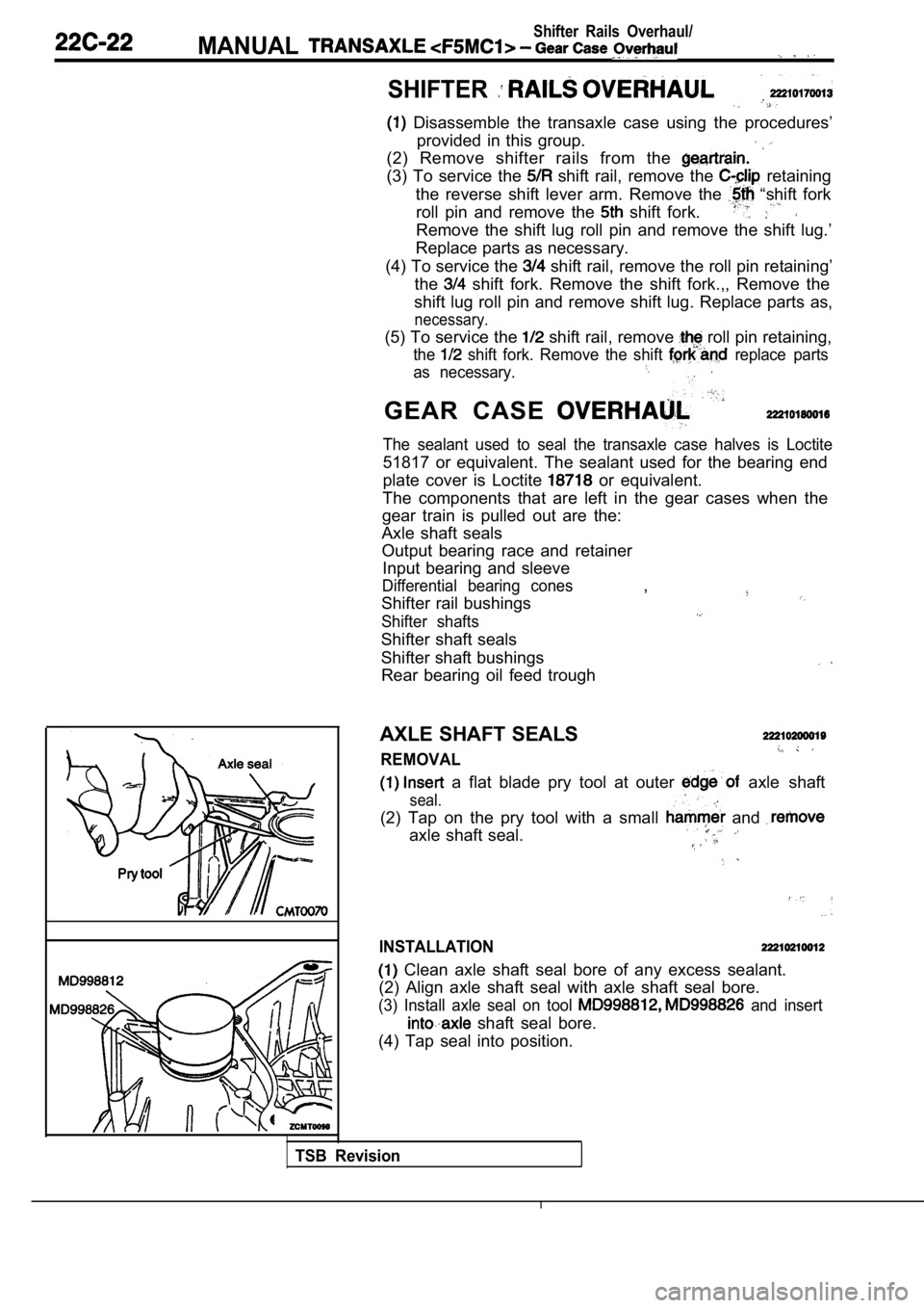
AXLE SHAFT SEALS
REMOVAL
a flat blade pry tool at outer axle shaft
seal.
(2) Tap on the pry tool with a small and
axle shaft seal.
INSTALLATION
Clean axle shaft seal bore of any excess sealant.
(2) Align axle shaft seal with axle shaft seal bore .
(3) Install axle seal on tool and insert
shaft seal bore.
(4) Tap seal into position.
TSB Revision