Page 996 of 2103
MANUAL TRANSAXLE Gear Case
SHAFT SEALS
It is not necessary to remove the shifter the trans-
axle to service the shifter shaft seals.
REMOVAL
(1) Using a pick tool, pry up the shifter seal and
remove seal from bore.
INSTALLATION
(1) Position new shifter shaft seal in bore.
(2) Install shifter shaft seal
bore using an
size deep well socket.
REMOVAL
(1) With the transaxle disassembled, remove the sel ector
shaft by pushing on the shaft from the outside and pulling
shaft out from the inside.
Reverse removal procedure to install selector shaft .
TSB Revision
REMOVAL
(1) With the transaxle disassembled, remove the crossover
shaft seal.
(2) Using snap ring pliers, remove the snap ring at the cross-
over shaft bore.
(3) Push the crossover shaft in the case and remove the
crossover assembly.
Reverse removal procedure to install crossover shaft.
Page 1009 of 2103

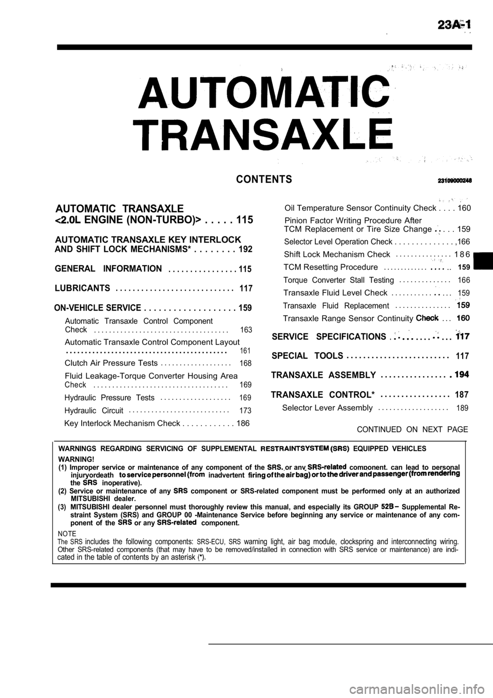
CONTENTS
AUTOMATIC TRANSAXLE
ENGINE (NON-TURBO)> . . . . . 115
AUTOMATIC TRANSAXLE KEY INTERLOCK
AND SHIFT LOCK MECHANISMS* . . . . . . . . 192
GENERAL INFORMATION
. . . . . . . . . . . . . . . . 115
LUBRICANTS. . . . . . . . . . . . . . . . . . . . . . . . . . . .117
ON-VEHICLE SERVICE . . . . . . . . . . . . . . . . . . . 159
Automatic Transaxle Control Component
Oil Temperature Sensor Continuity Check . . . . 160
Pinion Factor Writing Procedure After
TCM Replacement or Tire Size Change
. . . 159
Selector Level Operation Check . . . . . . . . . . . . . . ,166
Shift Lock Mechanism Check. . . . . . . . . . . . . . .
1 8 6
TCM Resetting Procedure . . . . . . . . . . . . .
..159
Torque Converter Stall Testing. . . . . . . . . . . . . .166
Transaxle Fluid Level Check . . . . . . . . . . .. . .159
Transaxle Fluid Replacement. . . . . . . . . . . . . . .
Transaxle Range Sensor Continuity . . .
Check. . . . . . . . . . . . . . . . . . . . . . . . . . . . . . . . . . . .163SERVICE SPECIFICATIONS.. . . .. . .Automatic Transaxle Control Component Layout
. . . . . . . . . . . . . . . . . . . . . . . . . . . . . . . . . . . . . . . . . . .
161SPECIAL TOOLS. . . . . . . . . . . . . . . . . . . . . . . . .117Clutch Air Pressure Tests . . . . . . . . . . . . . . . . . . .168
Fluid Leakage-Torque Converter Housing Area
Check. . . . . . . . . . . . . . . . . . . . . . . . . . . . . . . . . . . .169
Hydraulic Pressure Tests. . . . . . . . . . . . . . . . . . .169
Hydraulic Circuit. . . . . . . . . . . . . . . . . . . . . . . . . . .173
TRANSAXLE ASSEMBLY. . . . . . . . . . . . . . . .
TRANSAXLE CONTROL*. . . . . . . . . . . . . . . . .187
Selector Lever Assembly. . . . . . . . . . . . . . . . . . .189
Key Interlock Mechanism Check . . . . . . . . . . .
. 186CONTINUED ON NEXT PAGE
WARNINGS REGARDING SERVICING OF SUPPLEMENTAL EQUIPPED VEHICLES
WARNING! (1) Improper service or maintenance of any componen t of the
or any component, can lead to personal
injuryordeath inadvertent the inoperative).
(2) Service or maintenance of any component or SRS-related component must be perform ed only at an authorized
MITSUBISHI dealer.
(3)MITSUBISHI dealer personnel must thoroughly review this manual, and especially its GROUP Supplemental Re-
straint System (SRS) and GROUP 00 -Maintenance Serv ice before beginning any service or maintenance of any com-
ponent of the
or any component.
NOTEThe SRS includes the following components: SRS-ECU, SRS warning light, air bag module, clockspring and inte rconnecting wiring.Other SRS-related components (that may have to be removed/installed in connection with SRS service or maintenance) are indi-cated in the table of contents by an asterisk
Page 1010 of 2103

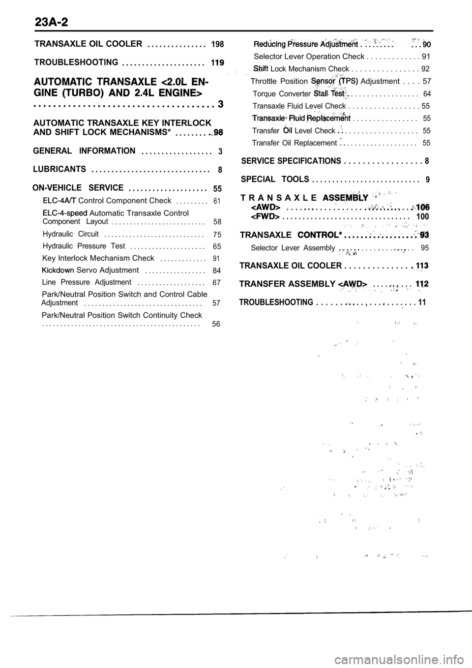
TRANSAXLE OIL COOLER. . . . . . . . . . . . . . .198
TROUBLESHOOTING. . . . . . . . . . . . . . . . . . . . .
AUTOMATIC TRANSAXLE KEY INTERLOCK
AND SHIFT LOCK MECHANISMS*
. . . . . . . .
GENERAL INFORMATION. . . . . . . . . . . . . . . . . .3
LUBRICANTS. . . . . . . . . . . . . . . . . . . . . . . . . . . . . .8
ON-VEHICLE SERVICE. . . . . . . . . . . . . . . . . . . .55
Control Component Check. . . . . . . . .61
Automatic Transaxle Control
Component Layout. . . . . . . . . . . . . . . . . . . . . . . . . .58
Hydraulic Circuit. . . . . . . . . . . . . . . . . . . . . . . . . . . .75
Hydraulic Pressure Test. . . . . . . . . . . . . . . . . . . . .65
Key Interlock Mechanism Check . . . . . . . . . . . . .91
Servo Adjustment. . . . . . . . . . . . . . . . .84
Line Pressure Adjustment
. . . . . . . . . . . . . . . . . . .67
Park/Neutral Position Switch and Control Cable
Adjustment. . . . . . . . . . . . . . . . . . . . . . . . . . . . . . . . .57
Park/Neutral Position Switch Continuity Check . . . . . . . . . . . . . . . . . . . . . . . . . . . . . . . . . . . . . . . . . . . .
56
, . .
Selector Lever Operation Check . . . . . . . . . . . . . 91
Lock Mechanism Check . . . . . . . . . . . . . . . . 92
Throttle Position Adjustment . . . . 57
Torque Converter . . . . . . . . . . . . . . . . .64
Transaxle Fluid Level Check . . . . . . . . . . . . . . . . . 55
. . . . . . . . . . . . . . . .55
Transfer Level Check . . . . . . . . . . . . . . . . . .55
Transfer Oil Replacement . . . . . . . . . . . . . . . . . .55
SERVICE SPECIFICATIONS . . . . . . . . . . . . . . . . . 8
SPECIAL TOOLS. . . . . . . . . . . . . . . . . . . . . . . . . . .9
T R A N S A X L E
. . . . . . . . . . . . . . . . .
. . . . . . . . . . . . . . . . . . . . . . . . . . . . . . . .100
TRANSAXLE
Selector Lever Assembly . . . . . . . . .95
TRANSAXLE OIL COOLER . . . . . . . . . . . . . .
TRANSFER ASSEMBLY . . . . . . .
TROUBLESHOOTING . . . . . . . . , . . . . . . . . . . 11
,
.
, . .
Page 1016 of 2103

AUTOMATIC TRANSAXLE ENGINEService
( T U R B O ) A N D E N G I N E > - . .
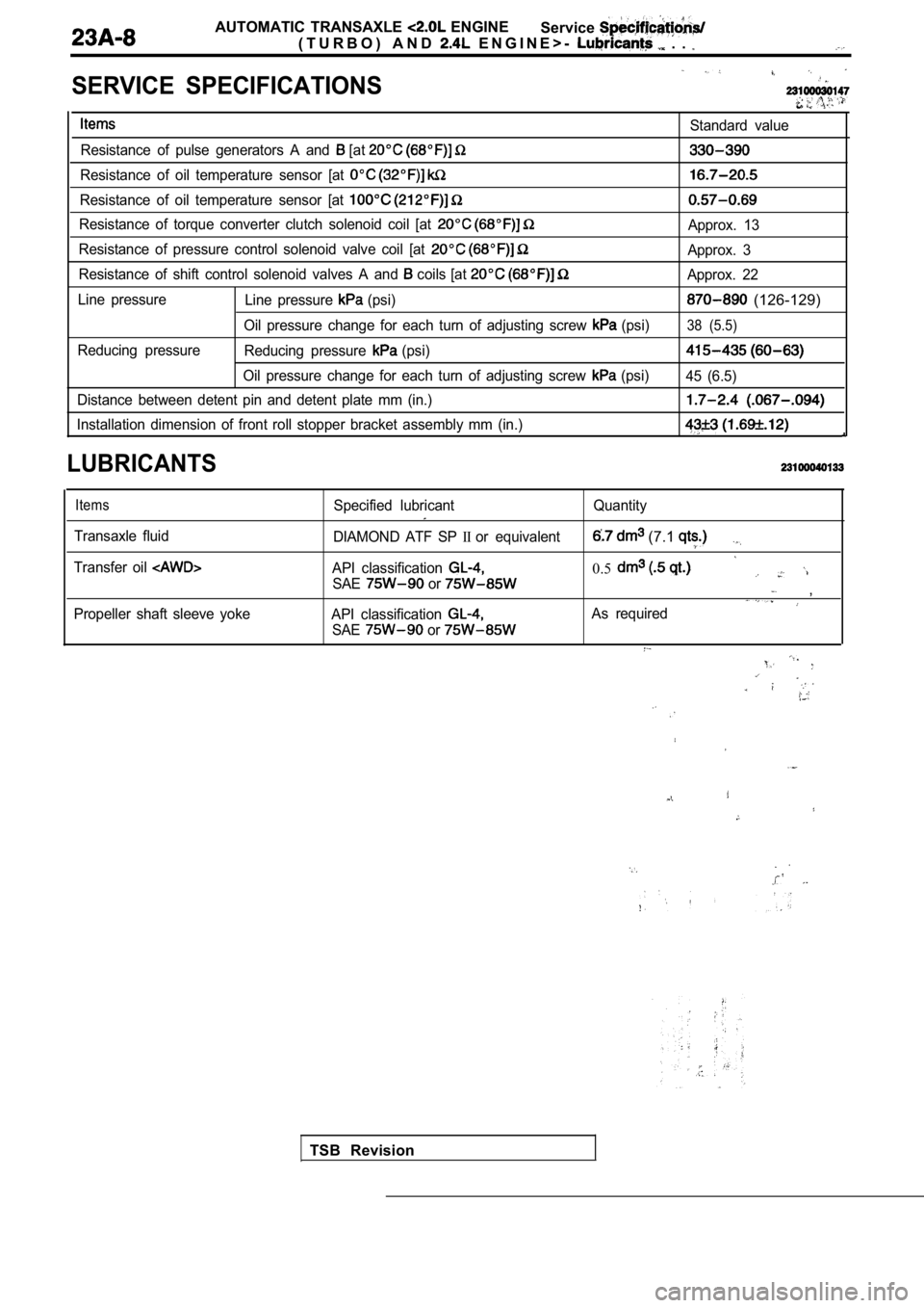
SERVICE SPECIFICATIONS
Standard value
Resistance of pulse generators A and
[at
Resistance of oil temperature sensor [at
Resistance of oil temperature sensor [at
Resistance of torque converter clutch solenoid coil [at Approx. 13
Resistance of pressure control solenoid valve coil [at
Approx. 3
Resistance of shift control solenoid valves A and
coils [at Approx. 22
Line pressure Line pressure
(psi) (126-129)
Oil pressure change for each turn of adjusting scre w (psi)38 (5.5)
Reducing pressure
Reducing pressure (psi)
Oil pressure change for each turn of adjusting scre w (psi)
45 (6.5)
Distance between detent pin and detent plate mm (in .)
Installation dimension of front roll stopper bracket assembly mm (in.)
LUBRICANTS
Items
Transaxle fluid
Transfer oil
Propeller shaft sleeve yoke Specified lubricant
Quantity
DIAMOND ATF SP
IIor equivalent (7.1
API classification 0.5SAE or ,
API classification As required
SAE
or
TSB Revision
Page 1018 of 2103
AUTOMATIC TRANSAXLE ENGINE
(TURBO) AND
ENGINE> S p e c i a l T o o l s
ToolTool number and name
461
460
Plug
General service tool*
G E N E R A L S E R V I C E
TOOL
Engine lifter
453
Engine hanger
assembly
TSB Revision
l Tie rod end ball joint andknuckle disconnectionLateral lower arm ball joir
and
lCompression, lower arm bajoint and tion
To prevent foreign substances
from entering transaxle case
l : Use shop towel
To support the engine assembly
during removal and installation of
the transaxle
To support the engine assembly
removal and installation of
transaxle
193
Plug
General service toolTo prevent foreign substances
from entering transfer
yoke holder
Hub fixing
Page 1053 of 2103
AUTOMATIC TRANSAXLE
ENGINE (TURBO) AND ENGINE> Troubleshooting
INSPECTION PROCEDURE 18l A/C load signal system
[Comment]In cases such as the above, the cause is probably a defective Idle position switch circuit.
Dual pressure switch check (Refer to
NG Replace
GROUP 55 On-vehicle Service.)
OK
Measure at TCM connector l connector and mea-sure at the harness side.
l Ignition switch: ON
l
switch: ON
lVoltage between terminals (8) and
ground
OK: Battery positive voltage
Check trouble symptom.
NG
P r o b a b l e
system check (Refer to GROUP
55 Troubleshooting.)
Replace the TCM. l
Malfunction of dual pressure
l Malfunction of l Malfunction of A/C system
l Malfunction of TCM
Check the following connectors:
TSB Revision. .
Page 1055 of 2103

AUTOMATIC TRANSAXLE
ENGINE (TURBO) AND ENGINE> Troubleshooting
SERVICE DATA REFERENCE TABLE
Item
No.Check item Check conditions condition
Fully closed
,000
Ignition: ON Gradually rises
11Throttle positionEngine: Stopped Depressed from the above
sensor Selector lever position:
value range
Fully open (for at least 2 se-,
Drive for 15 minutes or more
so that the automatic
15Oil temperature Warming up mission fluid temperature be-Gradually to
sensor
comes
70
Selector lever position:
range (vehicle stopped)
Idling (vehicle stopped)O N
OFF .
21
23
25
servo
switch
Ignition signal
Closed throttle
position switch Selector lever position:
2 range
Selector lever position:
range
Overdrive: OFF
Selector lever position:
range
Overdrive: ON
Selector lever position:
range
Selector lever position:
range
Overdrive: OFF
Ignition: ON
Engine: Stopped
Selector lever position:
range Driving at 10
mph)ON
Driving at constant speed of
40 km/h (20 seconds
OFF
o r m o r e )
Driving at constant speed of
50 km/h (31 mph) (20 seconds ON
or more)
Driving at constant speed of
50 km/h (31 mph) (20 seconds OFF
or more)
Idling (vehicle stopped) rpm
Driving at constant speed of
50 km/h (31 mph) (20 seconds rpm
or more).
O NFully closed
Depressed OFF
Fully open (for at least 2 se-,,
26A/C load signal Engine: Idling
Selector lever position:
range A/C switch: ON
A/C switch: OFF
ON
OFF
Revision
Page 1063 of 2103
AUTOMATIC TRANSAXLE
ENGINE (TURBO) AND ENGINE> On-vehicle Service
ON-VEHICLE SERVICE
TRANSAXLE FLUID LEVEL CHECK
Refer to GROUP 00 Maintenance Service.
TRANSAXLE FLUID REPLACEMENT23100100176
Refer to GROUP 00 Maintenance Service.
TRANSFER OIL LEVEL CHECK23100110025
Refer to GROUP 00 Maintenance Service.
TRANSFER OIL REPLACEMENT23100120023
Refer to GROUP 00 Maintenance Service.
TSB Revision