Page 1687 of 2103
P R O P O R T I O N I N G V A L V E,
REMOVAL AND INSTALLATION’.
O p e r a t i o n Operationl Brake Fluid DrainingLink Assembly Removal l Brakel l Engine (Turbo) and Engine>Brake Line fer l
Link Assembly Bolts Installation (Refer to GROUP Control.) Engine l Intake Manifold ( R e f e r ’ t o Engine (Non-turbo)> Intake Manifold (Refer to Manifold.) Engine ( R e f e r : G R O U P
Flared brake line nuts
11
TSB Revision
Removal steps
1. Brake pipe connection
2. Proportioning valve
0 0 0 0 0 0 7 4
Page 1688 of 2103
BASIC BRAKE ,
Connect the pipes to the
the ,
1. Proportioning valve Rear brake
2. Proportioning
3. Proportioning valve
4. Proportioning valve
5 . P r o p o r t i o n i n g v a l v e
6. valve M a s t e r
TSB Revision
Page 1689 of 2103
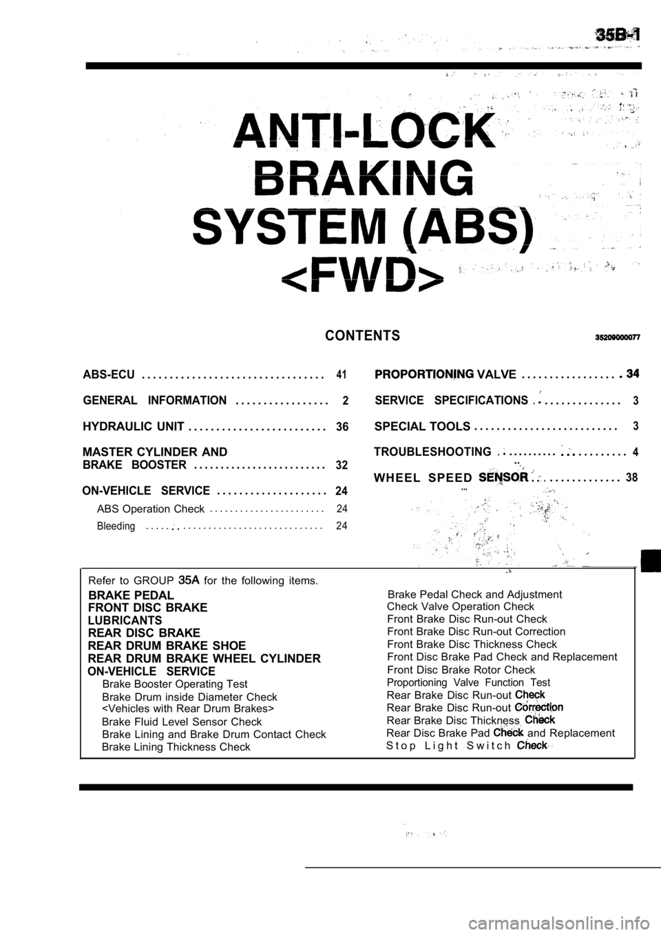
CONTENTS
ABS-ECU. . . . . . . . . . . . . . . . . . . . . . . . . . . . . . . . .41 VALVE. . . . . . . . . . . . . . . . .
GENERAL INFORMATION. . . . . . . . . . . . . . . . .2SERVICE SPECIFICATIONS.. . . . . . . . . . . . . .3
HYDRAULIC UNIT . . . . . . . . . . . . . . . . . . . . . . . . .36SPECIAL TOOLS . . . . . . . . . . . . . . . . . . . . . . . . . .3
MASTER CYLINDER ANDTROUBLESHOOTING.. . . . . . . . . .. . . . . . . . .4
BRAKE BOOSTER. . . . . . . . . . . . . . . . . . . . . . . . .32..
W H E E L S P E E D .. . . .... . . . . . . . . . . . .38
ON-VEHICLE SERVICE24.... . . . . . . . . . . . . . . . . . . .
ABS Operation Check . . . . . . . . . . . . . . . . . . . . . . .
24
Bleeding
. . . . .. . . . . . . . . . . . . . . . . . . . . . . . . . . .24
Refer to GROUP for the following items.
BRAKE PEDAL
FRONT DISC BRAKE
LUBRICANTS
REAR DISC BRAKE
REAR DRUM BRAKE SHOE
REAR DRUM BRAKE WHEEL CYLINDER
ON-VEHICLE SERVICE
Brake Booster Operating Test
Brake Drum inside Diameter Check
Brake Fluid Level Sensor Check
Brake Lining and Brake Drum Contact Check
Brake Lining Thickness Check
Brake Pedal Check and Adjustment
Check Valve Operation Check
Front Brake Disc Run-out Check
Front Brake Disc Run-out Correction
Front Brake Disc Thickness Check
Front Disc Brake Pad Check and Replacement
Front Disc Brake Rotor Check
Proportioning Valve Function Test
Rear Brake Disc Run-out
Rear Brake Disc Run-out
Rear Brake Disc Thickness
Rear Disc Brake Pad and Replacement
S t o p L i g h t S w i t c h
Page 1692 of 2103

ABS
TROUBLESHOOTING
DIAGNOSTIC TROUBLESHOOTING
Gather information from customer
.
Check diagnostic trouble code
(Refer to Check diagnostic trouble (Refer to
No diagnostic
trouble code or
with scan tool
Is the basic brake system functioning
normally?
Recheck trouble symptom.
Check diagnostic trouble codes
(Refer to
No diagnostictrouble
Inspection chart for trouble symptoms(Refer to Inspection chart for diagnostic troublecodes (Refer to
NOTES WITH REGARD TO DIAGNOSIS
The condition listed in the following table are con sidered normal.
ConditionExplanation of condition
No
.
TSB Revision
System check sound When starting the engine, a thudd
ing sound can sometimes be heard coming from inside.the engine compartment, but this is because the system operatioh check is being
performed. This is considered normal.
ABS operation sound
ABS operation (Long braking distance)1.Sound of the motor inside the ABS hydraulic unit. o perating (whine),
2. Sound is generated along with vibration of the b rake’ pedal.
3.When ABS operates, sound is generated from the vehi cle chassis due
brake application and release.
(Thump: suspension; squeak: tires)
For road surfaces such as snow-covered roads and gravel roads, the braking distance forvehicles with ABS can sometimes be longer than that for other vehicles. Accordingly,
advise the customer to drive safely on such roads by lowering the vehicle speed and not
being overconfident.
Diagnosis detection condition depends on the diagno stic trouble code.
Make sure that checking requirements listed in the “Comment” are satisfied when checking the trouble
symptom again after the diagnostic trouble code has been erased.
Page 1704 of 2103
6ABS
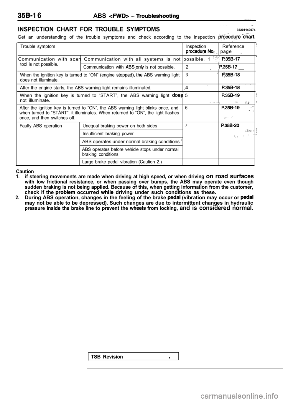
INSPECTION CHART FOR TROUBLE SYMPTOMS35201140074
Get an understanding of the trouble symptoms and check according to the inspection
Trouble symptom InspectionReference
p a g e
C o m m u n i c a t i o n w i t h s c a n C o m m u n i c a t i o n w i t h a l l s y s te m s i s n o t p o s s i b l e . 1
tool is not possible.
Communication with is not possible.2 __
When the ignition key is turned to “ON” (engine ABS warning light3
does not illuminate.
After the engine starts, the ABS warning light rema ins illuminated.
When the ignition key is turned to “START”, the ABS warning light 5
not illuminate.
After the ignition key is turned to “ON”, the ABS warning light blinks once, and6
when turned to “START”, it illuminates. When return ed to “ON”, the light flashes
once, and then switches off.
Faulty ABS operation Unequal braking power on both s ides7
Insufficient braking power
ABS operates under normal braking conditions
ABS operates before vehicle stops under normal
braking conditions
Large brake pedal vibration (Caution 2.)
Caution
1.if steering movements are made when driving at high speed, or when driving on road surfaces
with low frictional resistance, or when passing over bumps, the ABS may operate even though
sudden braking is not being applied. Because of thi s, when getting information from the customer,
check if the occurred driving under such conditions as these.
2.During ABS operation, changes in the feeling of the brake (vibration may occur or
may not be able to be depressed). Such changes are due to intermittent changes in hydraulic
pressure inside the brake line to prevent the from locking, and is considered normal.
TSB Revision,
Page 1712 of 2103
On-vehicle. Service
Check connector
l
harness
ON-VEHICLE SERVICE
C a u t i o n
Use the specified brake fluid. Avoid using a mixture of
the specified brake fluid and other fluid.
Specified brake fluid:
or
MASTER CYLINDER BLEEDING
Refer to GROUP
On-vehicle Service.
BRAKE LINE BLEEDING
Refer to GROUP
On-vehicle Service.
Caution
For with ABS, be sure to filter/strain the brake
fluid ‘being added to the master cylinder reservoir tank.
Debris may damage the HU.
OPERATION CHECK35200130101
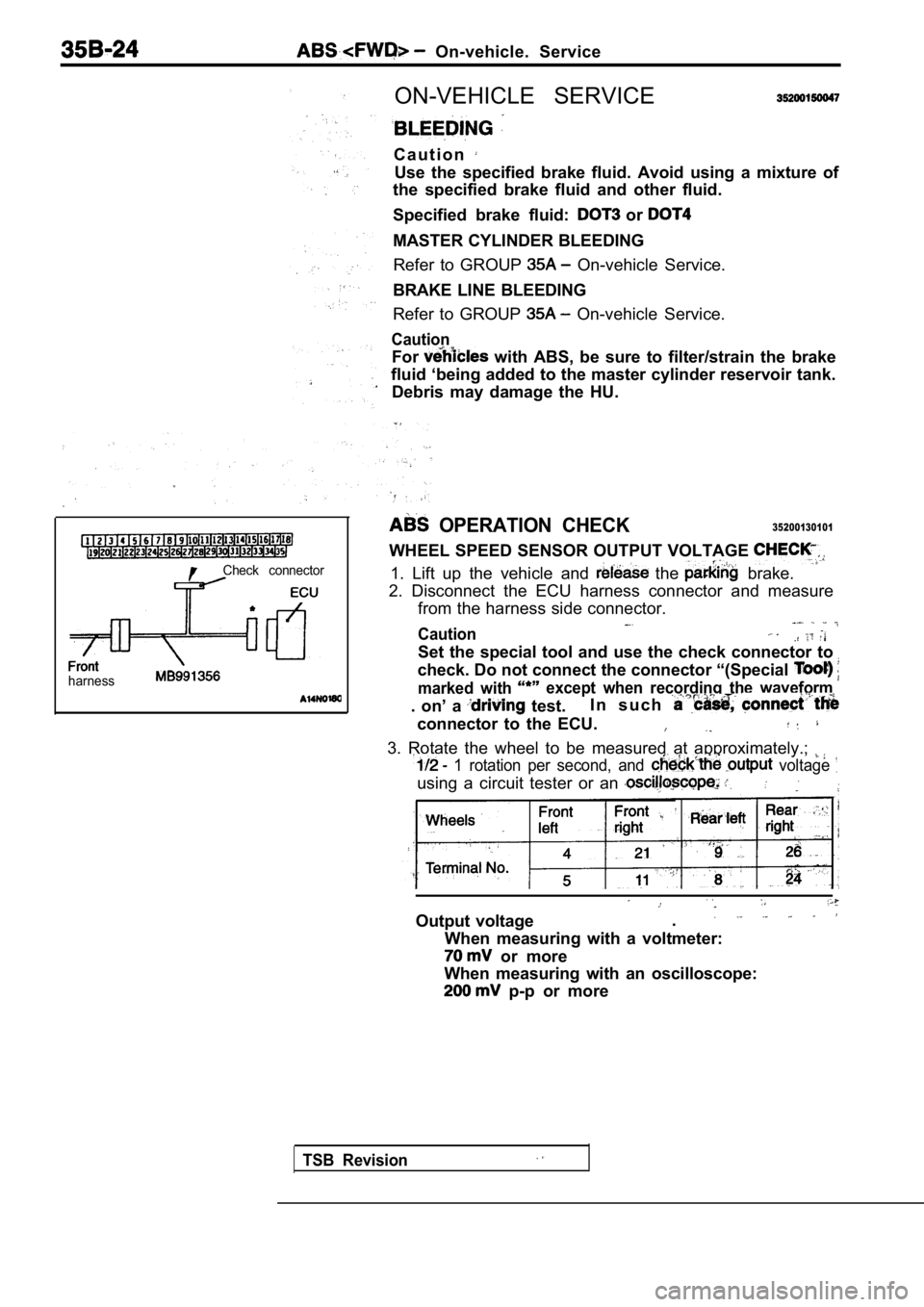
WHEEL SPEED SENSOR OUTPUT VOLTAGE
1. Lift up the vehicle and the brake.
2. Disconnect the ECU harness connector and measure from the harness side connector.
Caution
Set the special tool and use the check connector to
check. Do not connect the connector “(Special
marked with except when recording the waveform
. on’ a test. I n s u c h
connector to the ECU.
3. Rotate the wheel to be measured at approximately
.;
1 rotation per second, and voltage
using a circuit tester or an
Output voltage.
When measuring with a voltmeter:
or more
When measuring with an oscilloscope:
p-p or more
TSB Revision
Page 1715 of 2103
A B S
HYDRAULIC UNIT (HU) CHECK
Caution
35200170111
Turn the ignition switch off before connecting ordisconnecting the scan tool.
1.
up the vehicle and support the vehicle with rigid
racks placed at the specified jack-up points or pla ce the
wheels which are checked on the rollers of the brak ing
force tester.
Caution
1.The roller of the braking force tester and the tire
be dry during testing.
2.When testing the front brakes, apply the parking
brake, and when testing the rear brakes, stop the
front by chocking them.
2.Release the parking brake, and feel the drag force (drag
torque) on each road wheel.. __
When using the braking force tester, take a reading of’
the brake drag force.
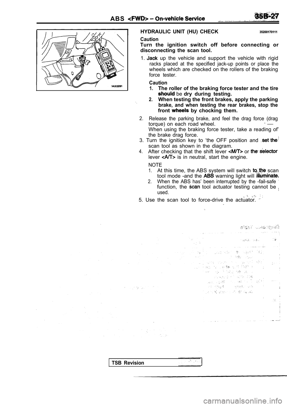
3. Turn the ignition key to ‘the OFF position and
scan tool as shown in the diagram.
4.After checking that the shift lever or
lever is in neutral, start the engine.
NOTE
1.At this time, the ABS system will switch scan
tool mode -and the
warning light will
2.When the ABS has’ been interrupted by the -fail-saf e
function, the tool actuator testing cannot be
used.
5. Use the scan tool to force-drive the actuator.
TSB Revision
Page 1716 of 2103
ABS On-vehicle Service
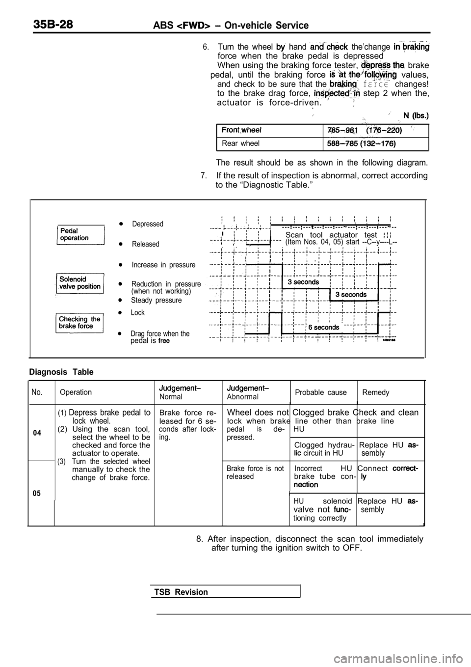
6.Turn the wheel hand the’change
force when the brake pedal is depressed
When using the braking force tester,
brake
pedal, until the braking force
values,
and check to be sure that the farce changes!
to the brake drag force, step 2 when the,
actuator is force-driven.
Rear wheel
The result should be as shown in the following diag ram.
7.If the result of inspection is abnormal, correct according
to the “Diagnostic Table.”
Depressed
Released
Increase in pressure
Reduction in pressure
(when not working)
Steady pressure
Lock
Drag force when the
pedal is
- - - ! - - - ; - - - t - - - ! - - - : - - - ~ - - - ; - - - : - - - i - - - ~ - -
I
Scan tool actuator test ,
, , (Item Nos. 04, 05) start --C--y----L--
, ,
Diagnosis Table
No.
04
Operation
(1)Depress brake pedal to
lock wheel.
(2) Using the scan tool,
select the wheel to be
checked and force the
actuator to operate.
(3)Turn the selected wheel
manually to check the
change of brake force.
05
Normal
Brake force re-
leased for 6 se-
conds after lock-
ing.
AbnormalProbable cause Remedy
Wheel does not Clogged brake Check and clean
lock when brake line other than brake line
pedalisde- HU
pressed.Clogged hydrau- Replace HU
circuit in HUsembly
Brake force is not IncorrectHU Connect
releasedbrake tube con-
HUsolenoid Replace HU
valve not sembly
tioning correctly
8. After inspection, disconnect the scan tool immed iately
after turning the ignition switch to OFF.
TSB Revision