Page 1719 of 2103
ABSOn-vehicle Service
Engine (Turbo)>When booster cables are used to start the engine when the
battery is completely
immediately driven without waiting for the battery to
itself to some extent, the engine may, making
driving difficult. 1’
This happens because ABS consumes. a great amount
current for its self-check function. The remedy is to either
allow the battery to recharge
or to remove the
fusible link for circuit, thus disabling the anti-lock brake
system.
The ABS warning light will illuminate, when link
(for
is removes.
After the battery has sufficiently charged, fusible
link (for
and restart the engine; then sure
the
warning light is not, illuminated.
Page 1720 of 2103
ABS Master Cylinder and Brake Booster
MASTER CYLINDER AND BRAKE BOOSTER
REMOVAL AND INSTALLATION
(Refer to GROUP Master Cylinder and Brake Booster.)
MASTER CYLINDER
DISASSEMBLY AND REASSEMBLY
. .
,
13
TSBRevision
19 14
15
Master cylinder kit
Brake fluid:
steps
Reservoir bracket2.Reservoir hose3. Reservoir cap assembly4.Diaphragm5.Reservoir cap6.Filter7. Brake fluid level sensor8,Float9.Reservoir10.Pin
Retainer12.Connector13.Grommet14. Piston stopper bolt15.Gasket
16. Piston stopper ring
17. Primary piston assembly
18. piston assembly19. Master cylinder body
CautionDo not disassemble the primary and secondary piston
assembly.
Page 1721 of 2103
ABS Master Cylinder and Brake’ Booster . . ,
Pistonstopper bolt PISTON STOPPER
Remove the piston stopper while depressing the piston.,
PISTON STOPPER RING DISASSEMBLY
Remove the piston stopper ring, while depressing th e piston.
INSPECTION
l <’ Check the inner surface of master cylinder body for
corrosion
lCheck the primary and secondary for corrosion,
scoring, damage or wear.
lCheck the diaphragm for
Page 1722 of 2103
ABS
PROPORTIONING VALVE
REMOVAL AND
Operationl Brake Fluid Draining
l Link Assembly Mounting Bolts Removal
Engine (Turbo) and Engine> (Refer to GROUP17 Auto-Cruise Control.)l Manifold Removal Engine (Non-turbo)>(Refer to GROUP 15 Intake Manifold.)
Flared brake line nuts
15 Nm
P o s t - i n s t a l l a t i o nl Brake Fluid. ing
l Brake
l L i n kEngine (Turboandbolts’ Installation (Refer to GROUP17 Auto-Cruise l Intake Engine
(Non-turbo)> (Refer to GROUP 15 IntakeManifold.)
TSB Revision
Removal steps
1. Brake pipe
2. Proportioning valve
Page 1724 of 2103

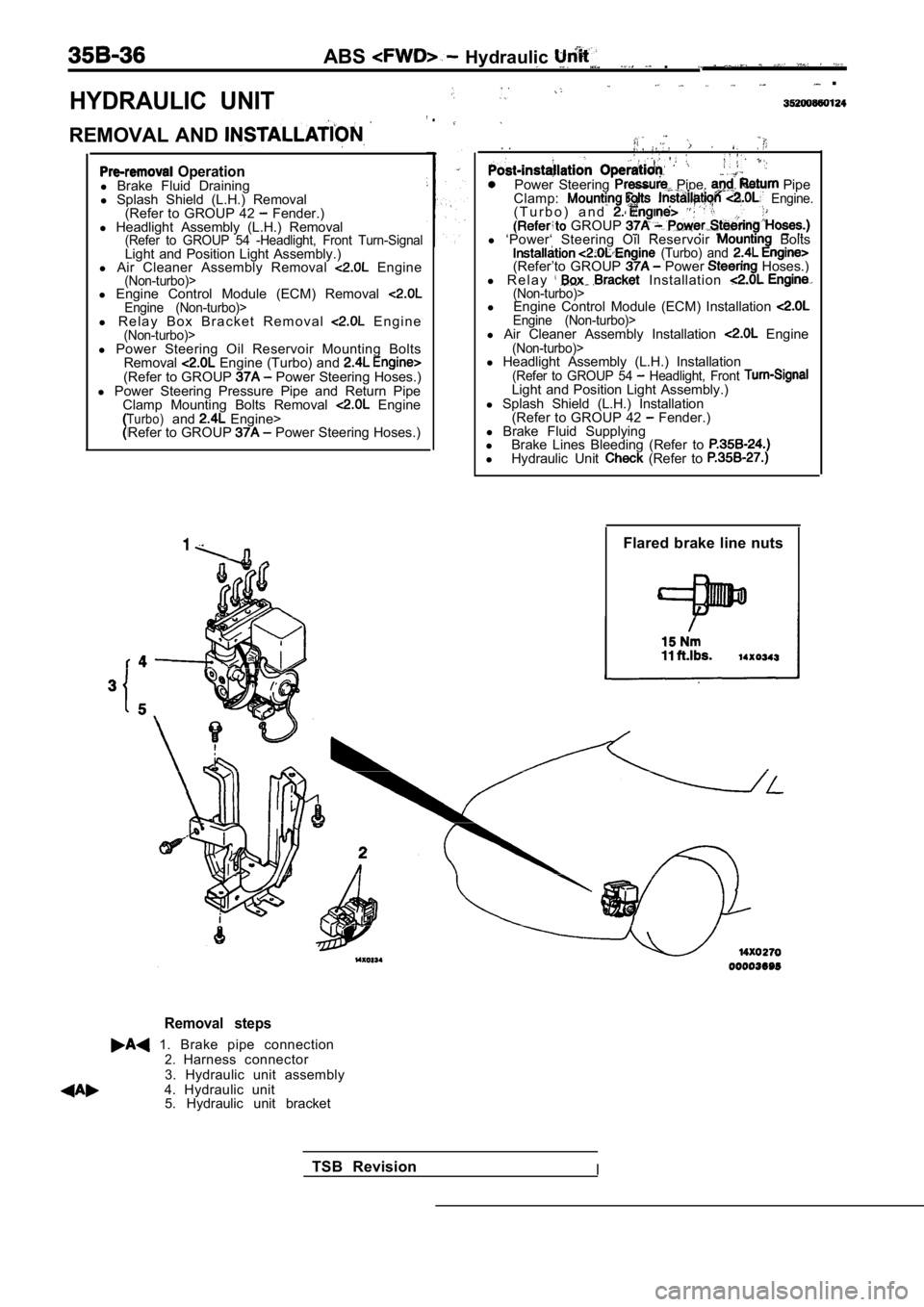
HYDRAULIC UNIT
ABS Hydraulic .
.
REMOVAL AND
.
Operationl Brake Fluid Draining
l Splash Shield (L.H.) Removal
(Refer to GROUP 42
Fender.)
l Headlight Assembly (L.H.) Removal
(Refer to GROUP 54 -Headlight, Front Turn-SignalLight and Position Light Assembly.)
l Air Cleaner Assembly Removal Engine(Non-turbo)>l Engine Control Module (ECM) Removal Engine (Non-turbo)>l R e l a y B o x B r a c k e t R e m o v a l E n g i n e(Non-turbo)>
Power Steering Pipe, Pipe
Clamp: Engine.( T u r b o ) a n d . GROUP l ‘Power‘ Steering Oil Reservoir Bolts (Turbo) and (Refer’to GROUP Power Hoses.)
l R e l a y Installation (Non-turbo)>l Engine Control Module (ECM) Installation Engine (Non-turbo)>l Air Cleaner Assembly Installation Engine(Non-turbo)>l Power Steering Oil Reservoir Mounting Bolts
Removal Engine (Turbo) and (Refer to GROUP Power Steering Hoses.)
l Power Steering Pressure Pipe and Return Pipe
Clamp Mounting Bolts Removal
EngineTurbo)and Engine>
Refer to GROUP Power Steering Hoses.) l
Headlight Assembly (L.H.) Installation
(Refer to GROUP 54 Headlight, Front Light and Position Light Assembly.)
l Splash Shield (L.H.) Installation
(Refer to GROUP 42
Fender.)
l Brake Fluid Supplying
l Brake Lines Bleeding (Refer to
lHydraulic Unit (Refer to
Flared brake line nuts
Removal steps
1. Brake pipe connection2.Harness connector
3. Hydraulic unit assembly
4. Hydraulic unit 5. Hydraulic unit bracket
TSB Revision
I
Page 1726 of 2103
ABS W h e e l S p e e d S e n s o r
WHEEL SPEED SENSOR
REMOVAL AND INSTALLATION
Operationl Splash Shield Removal
Installation Splash Shield
Front ,
Rear 49-59
74-66
4
Front wheel speed sensor removalsteps
1. Clip 2. Front wheel speed sensor Front ABS rotor removal3. Drive shaft
(Refer to GROUP 26 Drive
Shaft.)
Rear wheel speed sensor removal
4. Rear wheel speed sensor
Rear ABS rotor removal steps
5. Caliper assembly
6. Brake disc
7. Shoe and lining assembly
(Refer to GROUP 36 Parking
Brake Drum.)8. Rear hub assembly
9. Rear ABS rotor
NOTEThe front ABS rotor, integrated with the drive shaf t, can not be dis-assembled.
TSB Revision
Page 1731 of 2103

CONTENTS
ABS-ECU. . . . . . . . . . . . . . . . . . . . . . . . . . . . . . . . .31 SERVICE SPECIFICATIONS . . . . . . . . . . . . . . . . . 3
GENERAL INFORMATION2SPECIAL TOOLS. . . . . . . . . . . . . . . . . . . . . . . . . . .3. . . . . . . . . . . . . . . . . .
G-SENSOR2 9. . . . . . . . . . . . . . . . . . . . . . . . . . . . . . .4
ON-VEHICLE SERVICE . . . . . . . . . . . .
. . . . 21WHEEL SPEED . . . . . . . . . . . . . . . . . .
ABS Operation Check . . . . . . . . . . . . . . . . . . . . . . . 21
Refer to for the following items.
BRAKE PEDAL
FRONT DISC BRAKE
LUBRICANTS
REAR DISC BRAKE
REAR DRUM BRAKE SHOE
REAR DRUM BRAKE WHEEL CYLINDER
ON-VEHICLE SERVICE
Brake Booster Operating Test
Brake Drum Inside Diameter Check
with Rear Drum Brakes>
Brake Fluid Level Sensor Check
Brake Lining and Brake Drum
Contact Check
Brake Lining Thickness Check Brake Pedal Check and Adjustment
Check Valve Operation Check
Front Brake Disc Run-out Check
Brake
Front Check and
Front Check
Proportioning Valve Test
Rear Brake Check
Rear Brake Disc Run-out Correction
Rear Brake Disc Thickness Check
Rear Disc Brake Pad Check and Replacement
Stop Light Switch Check
Refer to GROUP for the following items.
H Y D R A U L I C U N I T
MASTER CYLINDER AND BRAKE BOOSTER
PROPORTIONING VALVE
ON-VEHICLE
,
Bleeding,
Page 1734 of 2103

ABS
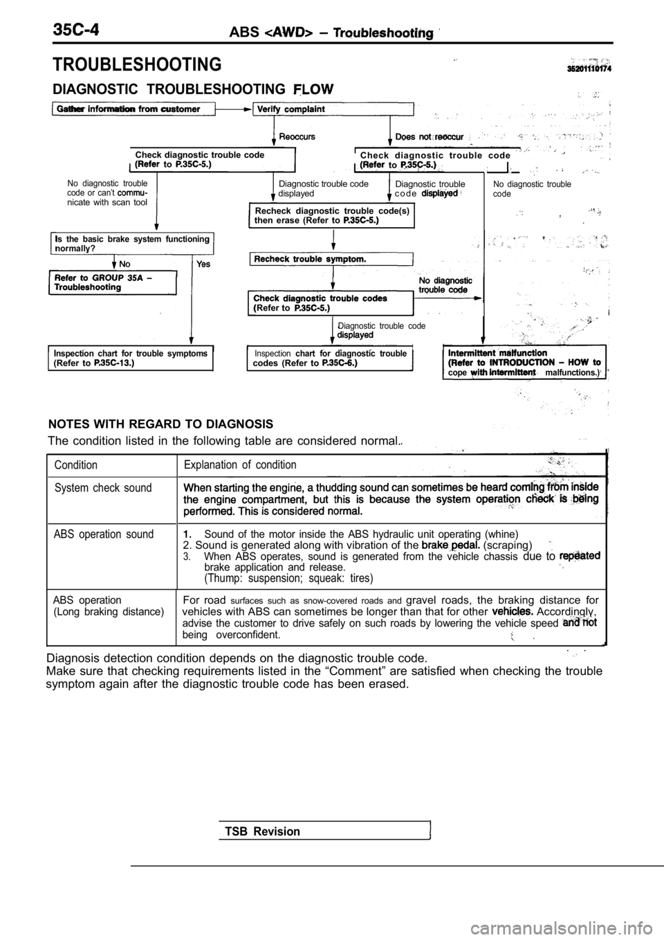
TROUBLESHOOTING
Check diagnostic trouble codeC h e c k d i a g n o s t i c t r o u b l e c o d e to to
No diagnostic troubleDiagnostic trouble codecode or can’t Diagnostic trouble
displayed c o d e
nicate with scan tool Recheck diagnostic trouble code(s)
then erase (Refer to
No diagnostic trouble
code
.
DIAGNOSTIC TROUBLESHOOTING
Gather information from customer
Is the basic brake system functioning
normallv?
(Refer to
Diagnostic trouble code
Inspection chart for trouble symptoms(Refer to Inspectionchart for diagnostic troubleII
codes (Refer to
cope malfunctions.)
NOTES WITH REGARD TO DIAGNOSIS
The condition listed in the following table are con sidered normal.
ConditionExplanation of condition
System check sound
TSB Revision
ABS operation soundSound of the motor inside the ABS hydraulic unit op erating (whine)2. Sound is generated along with vibration of the (scraping)
3.When ABS operates, sound is generated from the vehi cle chassis due to brake application and release.
(Thump: suspension; squeak: tires)
ABS operationFor road surfaces such as snow-covered roads and gravel roads, the braking distance for
(Long braking distance)vehicles with ABS can sometimes be longer than that for other Accordingly,
advise the customer to drive safely on such roads by lowering the vehicle speed
being overconfident.
. .
Diagnosis detection condition depends on the diagno stic trouble code.
Make sure that checking requirements listed in the “Comment” are satisfied when checking the trouble
symptom again after the diagnostic trouble code has been erased.