Page 1764 of 2103
PARKING BRAKES General Information
GENERAL29199919999
The parking brake is of a mechanical rear-wheelThe operation method utilizes a parking brake lever
brake construction in all vehicles. Drum-type or
drum in disc-type brakes are employed depending
which is in an offset position at the passenger’s
side.
on the vehicle model.
D I A G R A M .
TSB Revision
Page 1765 of 2103
PARKING BRAKES Service
SERVICE SPECIFICATIONS
ItemStandard valueLimitI
Parking brake lever strokeVehicles with brake3-5 notches
5-7 notches
.
Brake lining thickness mm (in.) 2.8
Brake drum inside diameter mm (in.)188.0 (6.8) 169.0 (6.7)
LUBRICANTS
.
ItemsSpecified lubricant
Backing plateBrake grease SAE No. 1
Shoe and lining assembly
Adjuster
TROUBLESHOOTING
Symptom Probable cause
Brake drag
lnsuff parking
brake function Incomplete release of parking brake.
Incorrect parking adjustment
W o r n b r a k e p a d
Excessive parking brake lever stroke
Grease or oil on pad surface Parking brake cable sticking’
Replace
Page 1766 of 2103

3 6 - 4P A R K I N G B R A K E S O n - v e h i c l e
PARKING BRAKE LEVER-
ADJUSTMENT
Pull ‘the parking brake lever with a force of appro
x.
(45 and count the number of notches.
Standard value:
3-5 notches
< V e h i c l e s w i t h
notches
Caution. . ,
The 196 (45 force of the brake
must be strictly observed.
2.If the parking stroke the standard
adjust as described below.
Remove the inner mat of the floor c&l-
sole.
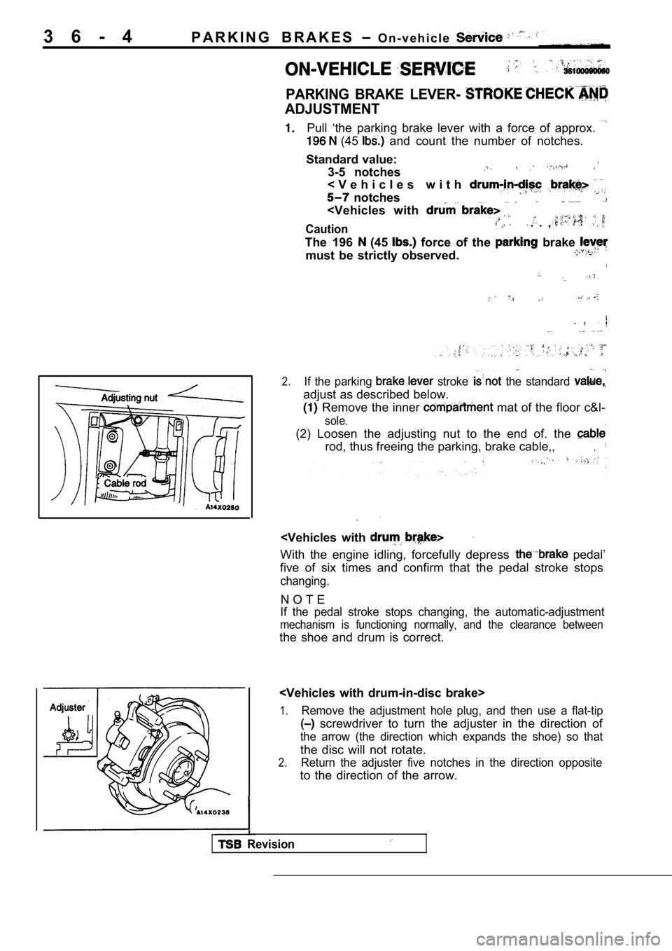
(2) Loosen the adjusting nut to the end of. the
rod, thus freeing the parking, brake cable,,
With the engine idling, forcefully depress pedal’
five of six times and confirm that the pedal stroke stops
changing.
N O T E
If the pedal stroke stops changing, the automatic-a djustment
mechanism is functioning normally, and the clearanc e between
the shoe and drum is correct.
1.Remove the adjustment hole plug, and then use a fla t-tip
screwdriver to turn the adjuster in the direction of
the arrow (the direction which expands the shoe) so that
the disc will not rotate.
2.Return the adjuster five notches in the direction opposite
to the direction of the arrow.
Revision
Page 1767 of 2103

P A R K I N G B R A K E S
Adjusting nut
Pin
Nut holder,
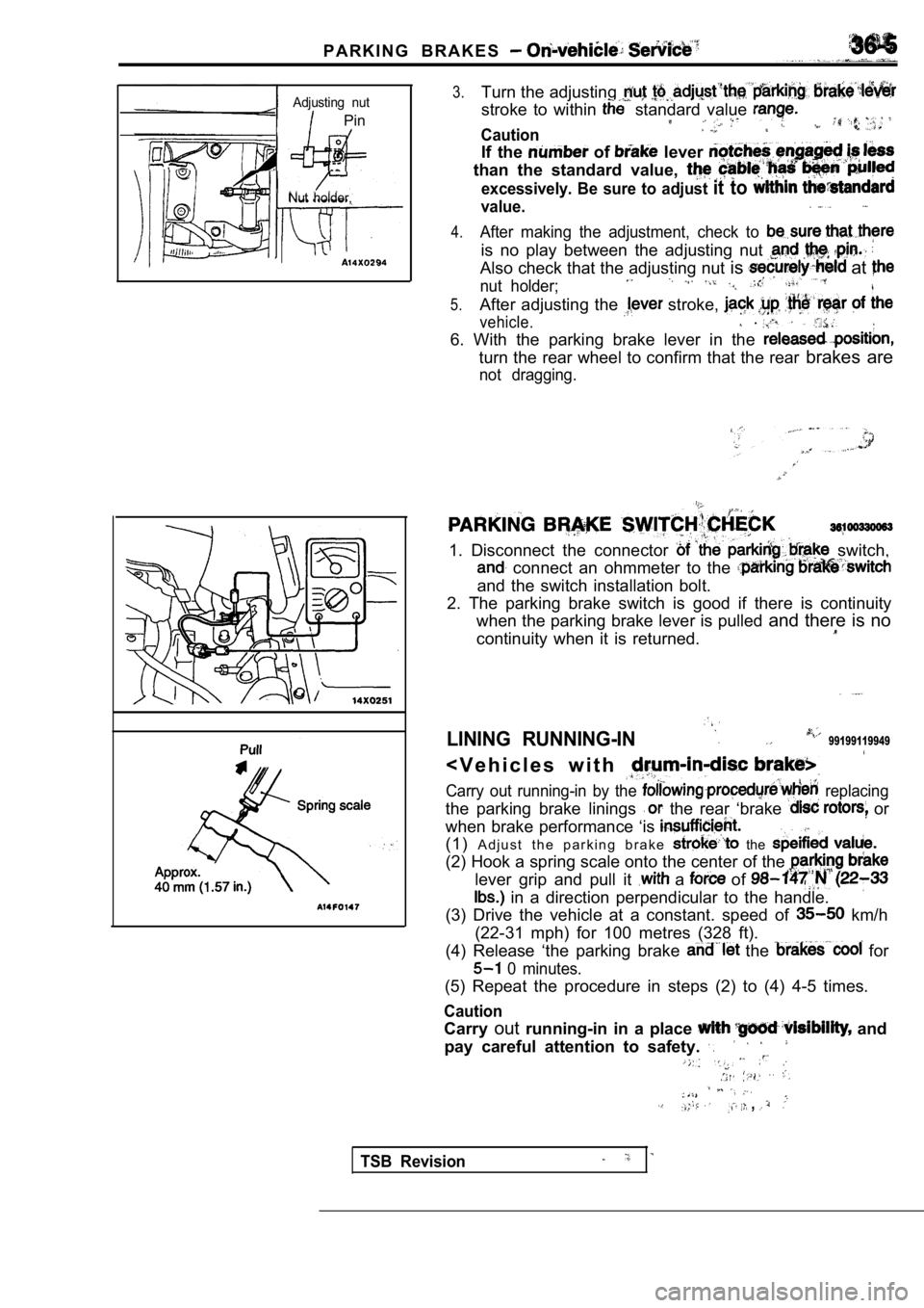
3.Turn the adjusting
stroke to within standard value
Caution
If the of lever
than the standard value,
excessively. Be sure to adjust it to
value.
4.After making the adjustment, check to
is no play between the adjusting nut
Also check that the adjusting nut is at
nut holder;
5.After adjusting the stroke,
vehicle..
6. With the parking brake lever in the
turn the rear wheel to confirm that the rear brakes are
not dragging.
1. Disconnect the connector switch,
connect an ohmmeter to the
and the switch installation bolt.
2. The parking brake switch is good if there is con tinuity
when the parking brake lever is pulled and there is no
continuity when it is returned.
LINING RUNNING-IN99199119949
< V e h i c l e s w i t h
Carry out running-in by the replacing
the parking brake linings the rear ‘brake or
when brake performance ‘is
(1) A d j u s t t h e p a r k i n g b r a k e the
(2) Hook a spring scale onto the center of the
lever grip and pull it a of
in a direction perpendicular to the handle.
(3) Drive the vehicle at a constant. speed of
km/h
(22-31 mph) for 100 metres (328 ft).
(4) Release ‘the parking brake
the for
0 minutes.
(5) Repeat the procedure in steps (2) to (4) 4-5 ti mes.
Caution
Carryoutrunning-in in a place and
pay careful attention to safety.
,
TSB Revision
Page 1768 of 2103
PARKING BRAKES Parking . .
PARKING BRAKE LEVER
REMOVAL AND INSTALLATION
Operationl Floor Console Removal
(Refer to GROUP Floor Console.)
CAUTION: SRS1.When removing and installing the floor console,
do not let it bump against the SRS-ECU or other
components.
2. Before removal of to GROUP SRS-ECU.
Post-installationl Parking Brake Lever Stroke (Refer to P. 36-4.)
l Floor Console
(Refer to GROUP Floor
4
Section A-ASection ‘B-B
Removal steps
1. Adjusting nut
2. Parking brake stay
3. Bushing
4. Parking brake switch 5. Parking brake lever
TSB Revision
Page 1769 of 2103
PARKING BRAKES Parking Brake Cable
REMOVAL AND INSTALLATION
OperationFloor Console Removal(Refer to GROUP Floor Console.)
Post-installation Operation lParking Lever
l Installation (Refer to GROUP Floor Console.)
CAUTION: SRS1.When removing and installing the floor console,
do not let it bump against the SRS-ECU or other
components.
2. Before removal of SRS-ECU, refer to GROUP SRS-ECU.
Removal steps
1. Rear brake drum2. spring3.Auto adjuster assemblyShoe-to-shoe spring4.5.Retainer spring
6. Lever return’
7.Shoe8.Shoe spring
10.11.Shoe’ arid C l i p
12. brake
TSB Revision
Page 1770 of 2103
36-8PARKING BRAKES Parking Brake Cable
PARKING BRAKE CABLE BRAKE>
REMOVAL AND INSTALLATION.
Operationl Floor Removal(Refer to GROUP Floor Console.)Parking Brake Lever Stroke
(Refer to GROUP Floor Console.)
CAUTION: SRS1.When removing and the floor console,
do not let it bump against the SRS-ECU or other
components.
2. Before removal of SRS-ECU, refer to GROUP SRS-ECU.II .
l ,
1349-59 Nm36-43
Removal steps
1. Rear brake assembly
2. Rear brake disc
3. spring (rear) 4. Shoe-to-anchor spring (front) 5. Adjusting wheel spring
Page 1771 of 2103
PARKING BRAKES, parking Brake Brake>
Shoe
Paint
Shoe-to-anchor spring (rear)
Forward
R E M O V A L
REAR BRAKE.
Remove the rear brake assembly and ‘support.
or similar.
,
SHOE HOLD-DOWN
Extend the shoe assembly, and remove the shoe
h o l d - d o w n c u p .
INSTALLATION
ADJUSTER
Install the adjuster so that the shoe adjusting-bol t of left hand
wheel ‘is attached towards the front the’ vehicle, and the
shoe adjusting bolt of right hand wheel is towards the rear
of the vehicle.
SPRING INSTALLATION
The the respective shoe-to-anchor different,
so the, spring in the figure has been
NOTE
The shows the left wheel; for the right the
position is symmetrical.
TSB Revision