Page 1663 of 2103

BASIC BRAKE SYSTEM Master Cylinder and Brake Booster
MASTER CYLINDER AND BRAKEBOOSTER
REMOVAL AND INSTALLATION
Pre-removal Operationl
Brake Fluid Draining
l Clutch Fluid Reservoir Bracket
(Refer to GROUP Clutch Control.)
l Battery Removal Engine (Non-turbo)>
l Relay Assembly Mounting Bolts Removal
Engine (Non-turbo)>
lWasher Tank Bolts Removal (Non-turbo)>lCentermember Assemblv Bolts Removal Engine (Turbo) arid Engine> (Refer toGROUP 32 Engine Roll Stopper, Centermember.)l Engine Mount Bracket Removal Engine
(Turbo) and Engine> (Refer to GROUP 32 Engine Mounting.)l Air Conditioning Compressor Mounting Bolts
Removal Engine (Turbo) and Engine>
(Refer to GROUP 55 Compressor and TensionPulley.)l Air Conditioning High Pressure Hose ClampMounting Bolts Engine (Turbo) and Engine>
l Power Steering Pressure Hose, Pipe and Return
Pipe Clamp Mounting Bolts Removal Engine and
I GROUP Power Steering Hoses.)
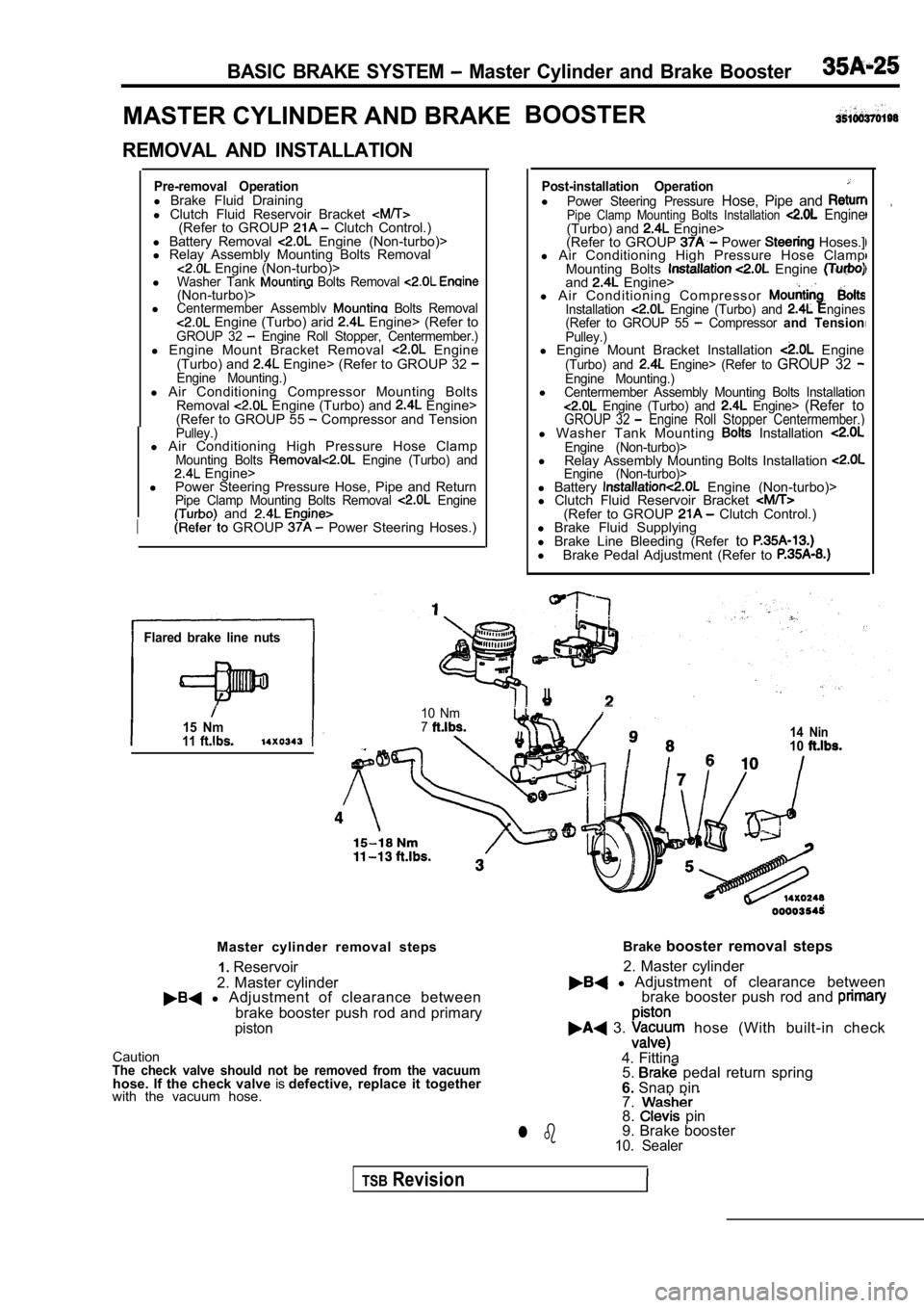
Flared brake line nuts
15 Nm11
Post-installation OperationlPower Steering Pressure Hose, Pipe and Pipe Clamp Mounting Bolts Installation Engine(Turbo) and Engine>
(Refer to GROUP Power Hoses.]
l Air Conditioning High Pressure Hose Clamp
Mounting Bolts
Engine and Engine>
l A i r C o n d i t i o n i n g C o m p r e s s o r
Installation Engine (Turbo) and ngines
(Refer to GROUP 55 Compressor and TensionPulley.)l Engine Mount Bracket Installation Engine(Turbo) and Engine> (Refer to GROUP 32 Engine Mounting.)lCentermember Assembly Mounting Bolts Installation Engine (Turbo) and Engine> (Refer toGROUP 32 Engine Roll Stopper Centermember.)l Washer Tank Mounting Installation Engine (Non-turbo)>l
Relay Assembly Mounting Bolts Installation Engine (Non-turbo)>l Battery Engine (Non-turbo)>
l Clutch Fluid Reservoir Bracket
(Refer to GROUP Clutch Control.)
l Brake Fluid Supplying
l Brake Line Bleeding (Refer to
l
Brake Pedal Adjustment (Refer to
I
10 Nm714 Nin10
Master cylinder removal steps
2. Master cylinder1.
Reservoir
l Adjustment of clearance between
brake booster push rod and primary
piston
CautionThe check valve should not be removed from the vacu umhose. If the check valve isdefective, replace it together
with the vacuum hose. Brake
booster removal steps
l Adjustment of clearance between
2. Master cylinder
brake booster push rod and
3. hose (With built-in check
4. Fittina 5.
pedal return spring
6. Snap pin
7.
8. pin
9. Brake booster
10. Sealerl b
TSBRevision
Page 1664 of 2103
BASIC BRAKE SYSTEM, Master Cvlinder Brake Booster”
Grease points
Fitting
ATD Part No. 8861
o r e q u i v a l e n t
1 4 1 0 2 4 9
SERVICE POINT
BOOSTER REMOVAL Engine
(Turbo) and
Engine>
Slide the engine forward and remove the brake boost er from
,
TSB Revision
Page 1665 of 2103
BASIC BRAKE SYSTEM Master Cylinder arid Brake
m m
Marking
Prima
piston Push rod
Straight scale
- -
INSTALLATION SERVICE POINTS
HOSE CONNECTION
(1) Install the vacuum hose to the brake
nipple
shown in the figure. Secure the hose with the hose clip.
Caution
1. The check valve and the pipe part of
booster must not contact each other.
2. Connect so that the marking faces upwards.
(2) Install the other end of the vacuum hose fully onto its
port on the engine. Secure the hose using the hose clip.
CLEARANCE ADJUSTMENT BETWEEN BRAKE
BOOSTER PUSH ROD AND PRIMARY PISTON
Adjust the clearance (A) between the brake booster push
rod and
piston as follows:
Calculate clearance A from the
and measurements.
Standard value: mm in.)
NOTE
When brake booster negative pressure 67 (9.7 psi) is applied,
clearance value will become mm in.)
Straight scale
Page 1666 of 2103
BASIC BRAKE SYSTEM Master Brake Booster
If the clearance is not within the standard
turn
the
screw to achieve desired length.
‘ I
.
,
TSB Revision
Page 1667 of 2103
BASIC BRAKE SYSTEM Master and ‘Brake
MASTER CYLINDER
DISASSEMBLY AND REASSEMBLY
Disassembly steps
1.Reservoir bracket2.Reservoir hoses3. Reservoir cap assembly4.Diaphragm5.Reservoir cap6. Brake fluid level sensor
7.Float8.Reservoir9.Pin10.Retainer
Master cylinder kit
Brake fluid:
or
11.Connector12.Grommet13. Piston stopper ring14. Primary piston assembly15. Secondary piston assembly16. Master cylinder body
CautionDo not disassemble the and secondaryassemblies.
DISASSEMBLY SERVICE POINT
(A, PISTON STOPPER RING DISASSEMBLY
Remove thepiston stopper ring, while depressing the piston.
TSB Revision
Page 1668 of 2103
BASIC BRAKE SYSTEM Master Cvlinder and’
INSPECTION
Check the inner
or pitting.
Check the primary and secondary pistons for rust, s coring,
wear, damage or wear.
Check the diaphragm for cracks and wear.
TSB Revision
Page 1669 of 2103
BASIC SYSTEM Front
FRONT DISC BRAKE
REMOVAL AND ,
I1I Operation
l Brake Fluid DrainingPost-installation Operationl Brake Fluid Supplying
lBrake Line Bleeding (Refer to
I
88Nm6 5
Removal steps
1. Brake hose connection
2.Gasket assembly
INSTALLATION SERVICE
FRONT BRAKE ASSEMBLY INSTALLATION
Install the front brake assembly and measure the disc brake
drag torque. (Refer to
INSPECTION
Check the brake disc for damage.
TSB Revision
Page 1670 of 2103
BASIC BRAKE SYSTEM Front Disc Brake
DISASSEMBLY AND REASSEMBLY
74 Nm542
74 Nm
54
4
5 7
Brake caliper kitPad repair kit
Seal and boots repair kit
Caliper assembly disassembly Pad assembly disassembl
y steps
steps 1. Guide pin 1. Guide pin 2. Lock pin 2. Lock pin 3. Bushing3.Bushing4. Caliper support (pad, clip, shim)
4. Caliper support (pad, clip, shim) 11. Pad and wear indicator assembly
5.Boot12. Pad assembly6.Boot ring
13. Outer shim (stainless)7.Piston boot14. Outer shim (coated with rubber)
8.Piston15. Inner shim (stainless)9.Piston seal16. Inner shim (coatedwith rubber)
10.Caliper body 17.
Clip
TSB Revision