Page 1647 of 2103

BASIC BRAKE SYSTEM
CLEARANCEB E T W E E N B R A K E A N D
REWALL
(1) Turn up thecarpet,etc. under the brake pedal,
(2) Start the engine, depress the brake pedal
with
490 (110 of force.
Standard value 90 mm (3.5 in.)
(3)If the clearance is less than the standard value, c
heck
for air trapped in the brake line,
the lining and the drum, and dragging in the parkin g
brake.
Adjust and replace defective parts as required.
(4) Turn back the carpet,
, .
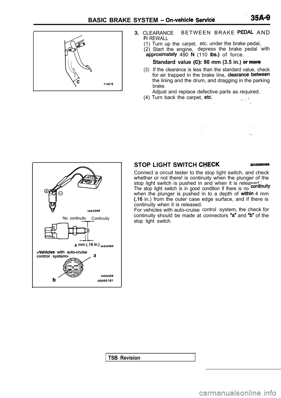
No continuity Continuity
4
with auto-cruise
control systema
STOP LIGHT SWITCH
Connect a circuit tester to the stop light switch, and check
whether or not there! is continuity when the plunge r of the
stop light switch is pushed in and when it is relea sed.’
The stop light switch is in good condition if there is no
when the plunger is pushed in to a depth of 4 mm
in.) from the outer case edge surface, and if ther e is
continuity when it is released. For vehicles with auto-cruise
controlsystem, the check for
continuity should be made at connectors
and of the
stop light switch.
TSB Revision
Page 1648 of 2103

BASIC BRAKE SYSTEM On-vehicle Service
GoodNo good
000001
When engine isWhen engine isstopped started
No goodGood
00000184BRAKE BOOSTER OPERATING
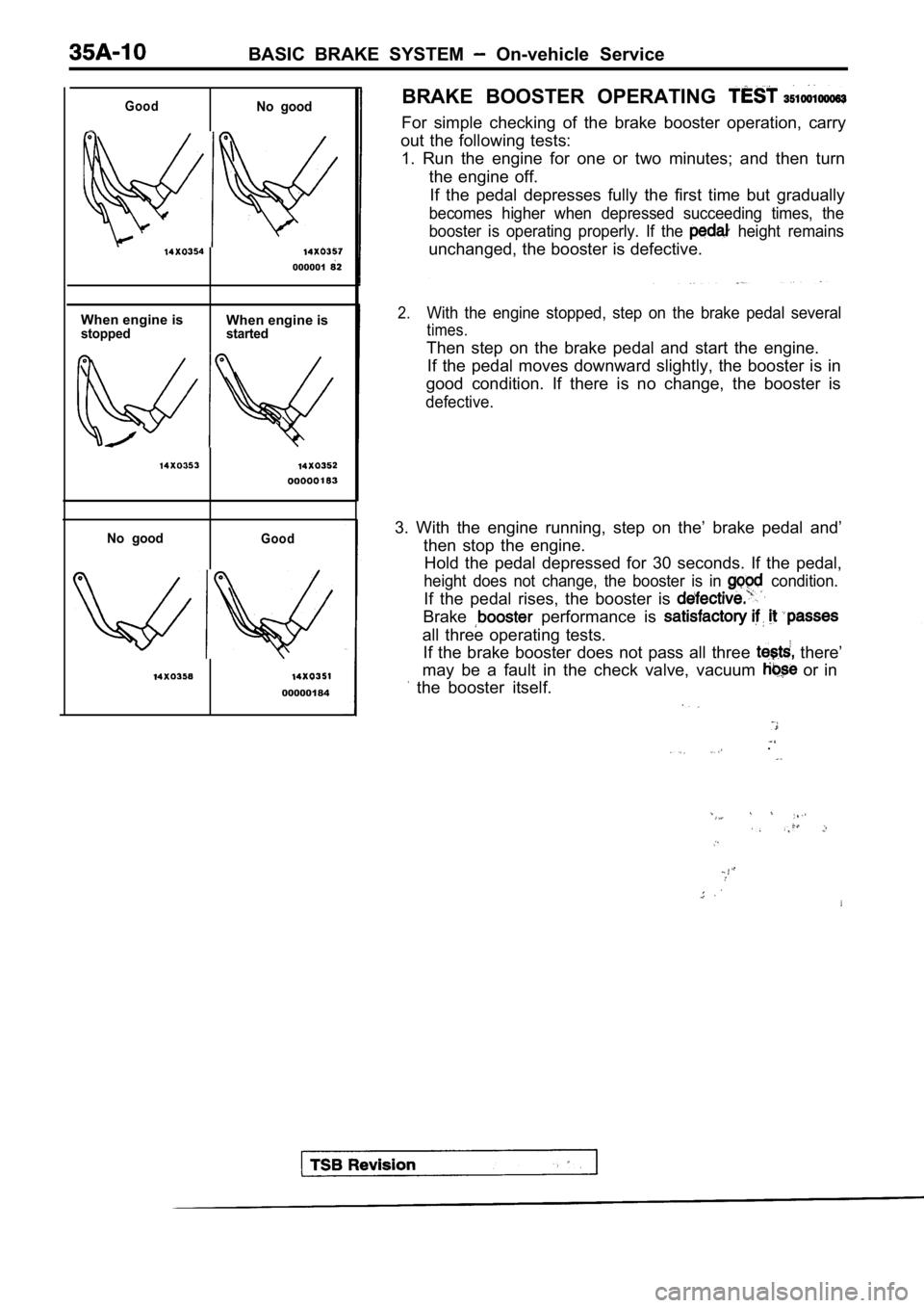
For simple checking of the brake booster operation,
carry
out the following tests: 1. Run the engine for one or two minutes; and then turn
the engine off. If the pedal depresses fully the first time but gra dually
becomes higher when depressed succeeding times, the
booster is operating properly. If the
height remains
unchanged, the booster is defective.
2.With the engine stopped, step on the brake pedal se veral
times.
Then step on the brake pedal and start the engine.
If the pedal moves downward slightly, the booster i s in
good condition. If there is no change, the booster is
defective.
3. With the engine running, step on the’ brake peda l and’
then stop the engine. Hold the pedal depressed for 30 seconds. If the ped al,
height does not change, the booster is in condition.
If the pedal rises, the booster is
Brake performance is
all three operating tests.
If the brake booster does not pass all three
there’
may be a fault in the check valve, vacuum
or in
the booster itself.
.
Page 1649 of 2103
BASIC BRAKE SYSTEM Service
Booster
side
CHECK VALVE OPERATION CHECK
When checking the check valve, keep the check valve fit
in the vacuum hose.,
1. Remove the vacuum hose.
NOTE
The check valve is press-fitted inside the vacuum h ose.
2.Check the operation of the check valve by using a v acuum
Vacuum pump connection Accept/reject criteria
Connection at the brake A negative pressure
booster side (A)is created and held.
Connection at the intake A (vacuum)
manifold side (B) is not created.
Caution
If the check valve is defective, replace it as an
assembly unit together with the vacuum hose.
TSB Revision
Page 1650 of 2103
BASIC BRAKE SYSTEM
Pressure gauge
v a l v e
S p l i t p o i n t S p l i t p o i n t
o u t p u t
o u t p u tpressurepressure
Input pressure
VALVE
.
1. two pressure gauges, one ‘each to the
side and output side of the proportioning
2. Air bleed the brake line and
3. While gradually depressing: the brake pedal, the
following measurements and’
be sure that
measured values are within, the allowable
.
Output pressure ‘begins to” drop ‘to input
p r e s s u r e ( s p l i t p o i n t ) .
S t a n d a r d v a l u e :
(2) Check that the output at the standard
value when the input fluid pressure increases;
according to the table
Standard value:
ItemsVehicles without Vehicles with
ABS ABS
TSB
Revision
Input fluid
pressure 6.07 (925) 6.86 (996)
Output fluid
pressure
3.92-4.41
(462-533)
(3) Output pressure difference between left and rig ht
brake lines
Limit: 0.4 (57 psi)
4.If the measured pressures are not within allowable ranges,
replace the proportioning valve.
Page 1651 of 2103
BASIC BRAKE SYSTEM
BRAKE CHECK 35190919953
The brake fluid
sensor is in good condition if there is
no continuity when the float surface is above
or “A”
and if there is continuity when the float surface i s below “MIN
or “A”.
BLEEDING
Caution
35199149955
Use the specified brake fluid. use mixture of the
specified brake fluid and another fluid.
Specified brake fluid:
CYLINDER BLEEDING
The master cylinder has no so if bleeding is
carried out by the following procedure, bleeding of air from
the brake line will become easier. (1) Fill the reserve tank
fluid.
(2). Keep the brake pedal depressed.
(3) Have another person cover the master cylinder outlet
with a finger.
(4) With the outlet still closed, release the brake pedal.
(5) Repeat steps
three or four times to fill the inside
of the master cylinder with brake fluid.
BRAKE LINE BLEEDING
Start the and bleed air sequence shown
in the figure.
Revision
Page 1652 of 2103
4 SYSTEM Service
Pad
indicator
Brake disc
BRAKE PAD CHECK AND . .
REPLACEMENT
brake ‘pads have wear that contact
disc when ‘the brake pad 2
The wear indicators a to warn
to have the pads replaced h&e
checked.
1.Check. brake pad.
port.
Standard’ 10 mm
,
Limit: 2.0 mm in.)
Caution
When the limit is pads on
both the left and be replaced
as a set.
2. If there is, a significant in the
thicknesses of the pads on the left and right sides,
the sliding condition- of -the
pin guide pin.
2. g u i d e c a l i p e r t h e ”
assembly toward, the inside of the wheel well
from the lock Support it
Caution
Donot wipe off the special guide
pin or allow it to
Page 1653 of 2103
BASIC BRAKE SYSTEM
Front hub assembly
196-255 Nm
145-188
3.
4.
5.
6.
8.
Remove the following parts from caliper support. 1. Pad and wear indicator assembly
2. Pad assembly
3. Clip
4 . O u t e r s h i m ( s t a i n l e s s )
5. Outer shim (coated with rubber)
6. Inner shim (stainless)
7. Inner shim (coated with rubber)
Take out the drive shaft. (Refer to GROUP 26
Drive
Shaft
to GROUP 26 Drive Shaft
Set the special tool to the front hub assembly as s hown
in the illustration.’
Measure hub torque (A) with pads removed to measure
brake drag torque. Torque value will be used later to
calculate brake drag force with the pads installed.
NOTE
Tighten the nuts in order to secure the disc to the hub.
Securely attach the pad clip to the caliper support .
Clean piston and insert into cylinder (caliper) with special
Page 1654 of 2103

BASIC BRAKE SYSTEM On-vehicle Service
Pad assembly
Grease
Grease Al
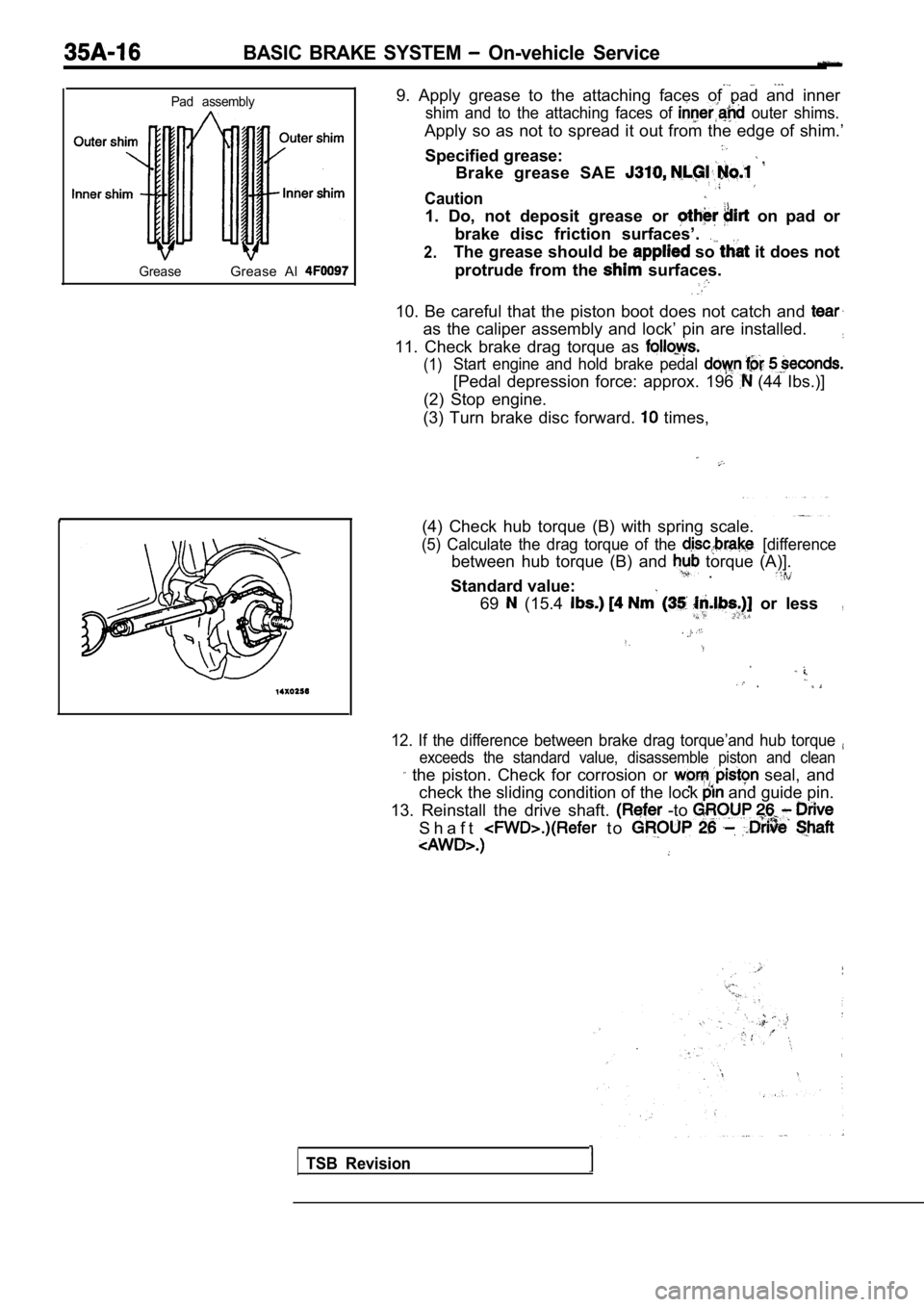
9. Apply grease to the attaching faces of pad and i nner
shim and to the attaching faces of outer shims.
Apply so as not to spread it out from the edge of shim.’
Specified grease:
Brake grease SAE
Caution
1. Do, not deposit grease or on pad or
brake disc friction surfaces’.
2.The grease should be so it does not
protrude from the
surfaces.
10. Be careful that the piston boot does not catch and
as the caliper assembly and lock’ pin are installed.
11. Check brake drag torque as
(1)Start engine and hold brake pedal
[Pedal depression force: approx. 196 (44 Ibs.)]
(2) Stop engine.
(3) Turn brake disc forward.
times,
(4) Check hub torque (B) with spring scale.
(5) Calculate the drag torque of the [difference
between hub torque (B) and torque (A)]. .
Standard value:
69 (15.4 or less,
12. If the difference between brake drag torque’and hub torque
exceeds the standard value, disassemble piston and clean
the piston. Check for corrosion or seal, and
check the sliding condition of the lock
and guide pin.
13. Reinstall the drive shaft.
-to
S h a f t t o
TSB Revision