Page 1346 of 2103
AUTOMATIC TRANSAXLE
OVERHAUL
both sun assembled’ in the previous
into the planetary carrier. .
the reaction brake and brake
TSB Revision
Page 1348 of 2103
AUTOMATIC TRANSAXLE
OVERHAUL
Transaxle
the pressure plate used in disassembly and
install the return spring.
Caution Position the return spring
when installing.
a coating of petrolatum jelly to the wave spring
and attach it to the center support.
the special tool on the center support, install 2
new O-rings and push into the transaxle case.
Caution
Coat the O-rings with automatic
and align the oil holes.
2. Do not move the wave spring out of position
installing.
the snap ring.
TSB Revision
a feeler gauge and measure the end play of the
low-reverse brake. Adjust to the standard value by select-
ing the proper pressure plate.
S t a n d a r d v a l u e : mm in.)
Page 1378 of 2103
AUTOMATIC TRANSAXLE
Low-reverse Brake
LOW-REVERSE BRAKE
DISASSEMBLY AND REASSEMBLY
1
T S B R e v i s i o n
Disassembly steps
1.Low-reverse brake piston2. D-ring3. D-ring
4. Center support
Page 1509 of 2103
I
8990767
ON-VEHICLE SERVICE
WHEEL BEARING END PLAY CHECK
1. Remove the disc brake caliper and suspend it with a
wire.
2. Remove the brake disc from the front hub.
3.Attach a dial gauge as shown in the illustration, and then
measure the end play while moving the hub in the ax ial
direction.
Limit: 0.05 mm in.)
4.If end play exceeds the replace the front hub assem-
bly.
HUB BOLT REPLACEMENT
1. Remove the caliper assembly and secure it with w ire
so that it does not fall.
2. Remove the brake disc.
3. Use the special tools to remove the hub bolts.
Caution
Be sure to tie the cord special tool to a nearby
part.
4.Use the wheel nuts to securely install the new hub bolts,
while being careful of the serrations of the hub bo lts and
hub;
TSB Revision
Page 1510 of 2103
26-6FRONT AXLE Front
FRONT HUB ASSEMBLY
REMOVAL AND INSTALLATION
88 Nm65
8885
Removal steps
1. Cotter pin 2. Drive shaft nut
3. Front wheel speed sensor
with 4. Caliper assembly
5. Brake disc
A l
Nut
Nm
145-188
5
Caution
6. Upper
7. Front hub.
The front hub assembly not be disassembled..
REMOVAL SERVICE POINTS
DRIVE SHAFT R E M O V A L .
CALIPER ASSEMBLY REMOVAL
Secure the removed caliper so that it
does not fall., ,
ARM BALL JOINT AND KNUCKLE
DISCONNECTION
Caution
1.Using the tool, loosen the tie rod end mounting
nut. Only loosen the nut; do not remove it from the
joint.
2.Support the tool with a cord, etc. to prevent
it from coming off.
TSB Revision
Page 1537 of 2103

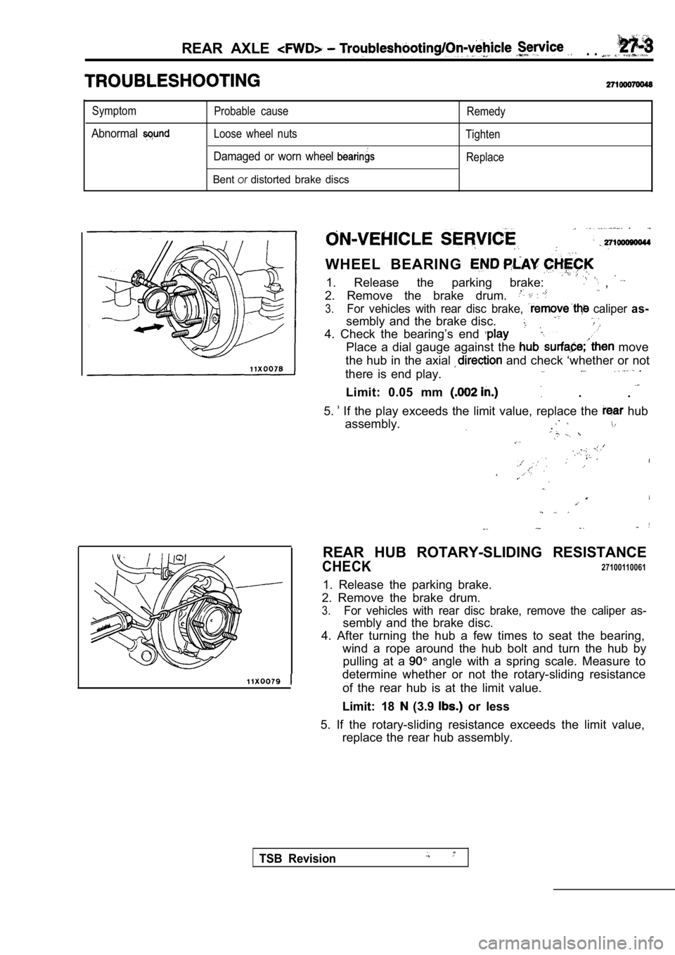
REAR AXLE . .
Symptom
Abnormal
Probable cause
Loose wheel nuts
Damaged or worn wheel
Bentordistorted brake discs
Remedy
Tighten Replace
WHEEL BEARING
1. Release the parking brake: ,
2. Remove the brake drum.
3.For vehicles with rear disc brake, caliper as-
sembly and the brake disc.
4. Check the bearing’s end
Place a dial gauge against the move
the hub in the axial
and check ‘whether or not
there is end play. .
.
Limit: 0.05 mm .
5.
If the play exceeds the limit value, replace the hub
assembly.
.
REAR HUB ROTARY-SLIDING RESISTANCE
CHECK27100110061
1. Release the parking brake.
2. Remove the brake drum.
3.For vehicles with rear disc brake, remove the calip er as-
sembly and the brake disc.
4. After turning the hub a few times to seat the be aring,
wind a rope around the hub bolt and turn the hub by pulling at a
angle with a spring scale. Measure to
determine whether or not the rotary-sliding resista nce
of the rear hub is at the limit value.
Limit: 18
(3.9 or less
5. If the rotary-sliding resistance exceeds the lim it value,
replace the rear hub assembly.
TSB Revision
Page 1538 of 2103
REAR AXLE On-vehicle Service
HUB BOLT
1. Remove the caliper assembly and with
so that it does not fall.
2. Remove the brake drum and- brake disc.
3.For vehicles with disc brakes;’
assembly..
4. Pull the hub bolt using the special
NOTE
For vehicles with drum
near the retainer in
order to maintain
C a u t i o n
Be sure to tie the cord of a nearby
part.,
5.Use the wheel nuts to securely install the new hub bolts,
while being careful of the serrations of the hub bo lts and
hub.
TSB Revision
.
,
,
,
Page 1539 of 2103
REAR AXLE Rear Hub Assembly
REMOVAL AND INSTALLATION
54-65
a
54-65
8
8
0 0 0 0 4 0 4 5
Removal steps
1. Rear wheel speed sensor
(Refer to GROUP WheelSpeed Sensor.)2.Caliper assembly3. Brake drum
4. Brake disc 5. Clip mounting bolt
6. Shoe and lining assembly (Refer
GROUP 36 Parking Brake.)
7. Rear hub assembly 8. ABS with
CautionThe rear hub assembly should not be disassembled.
TSB Revision