Page 1174 of 2103

AUTOMATIC TRANSAXLE
ENGINE (NON-TURBO)> On-vehicle Service
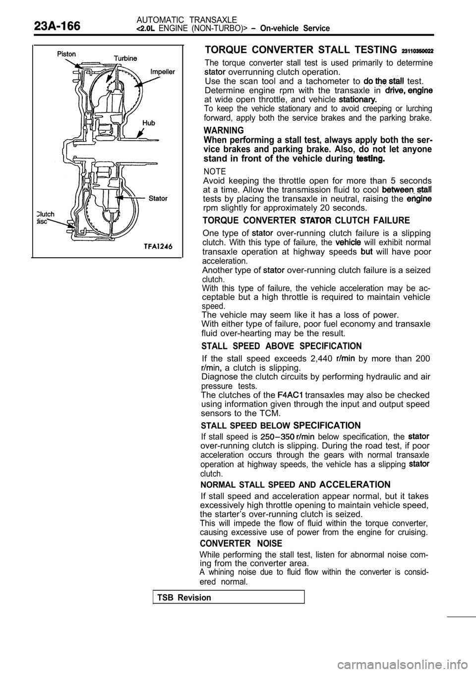
TORQUE CONVERTER STALL TESTING
The torque converter stall test is used primarily to determine
overrunning clutch operation.
Use the scan tool and a tachometer to
test.
Determine engine rpm with the transaxle in
at wide open throttle, and vehicle
To keep the vehicle stationary and to avoid creepin g or lurching
forward, apply both the service brakes and the parking brake.
WARNING
When performing a stall test, always apply both the ser-
vice brakes and parking brake. Also, do not let any one
stand in front of the vehicle during
NOTE
Avoid keeping the throttle open for more than 5 seconds
at a time. Allow the transmission fluid to cool
tests by placing the transaxle in neutral, raising the
rpm slightly for approximately 20 seconds.
TORQUE CONVERTER CLUTCH FAILURE
One type of over-running clutch failure is a slipping
clutch. With this type of failure, the will exhibit normal
transaxle operation at highway speeds will have poor
acceleration.
Another type of over-running clutch failure is a seized
clutch.
With this type of failure, the vehicle acceleration may be ac-
ceptable but a high throttle is required to maintai n vehicle
speed.
The vehicle may seem like it has a loss of power.
With either type of failure, poor fuel economy and transaxle
fluid over-hearting may be the result.
STALL SPEED ABOVE SPECIFICATION
If the stall speed exceeds 2,440 by more than 200
a clutch is slipping.
Diagnose the clutch circuits by performing hydrauli c and air
pressure tests.
The clutches of the transaxles may also be checked
using information given through the input and outpu t speed
sensors to the TCM.
STALL SPEED BELOW SPECIFICATION
If stall speed is below specification, the
over-running clutch is slipping. During the road te st, if poor
acceleration occurs through the gears with normal t ransaxle
operation at highway speeds, the vehicle has a slip ping
clutch.
NORMAL STALL SPEED AND ACCELERATION
If stall speed and acceleration appear normal, but it takes
excessively high throttle opening to maintain vehic le speed,
the starter’s over-running clutch is seized.
This will impede the flow of fluid within the torqu e converter,
causing excessive use of power from the engine for cruising.
CONVERTER NOISE
While performing the stall test, listen for abnormal noise com-
ing from the converter area.
A whining noise due to fluid flow within the conver ter is consid-
ered normal.
TSB Revision
Page 1179 of 2103

AUTOMATIC TRANSAXLE
On-vehicle Service
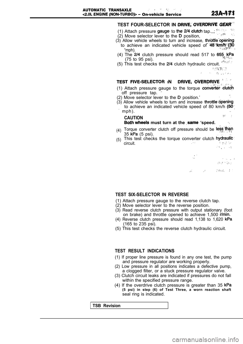
TEST FOUR-SELECTOR IN
(1) Attach pressure to tap.,,;
(2) Move selector lever to the position,
(3) Allow vehicle wheels to turn and increase,
to achieve an indicated vehicle speed of
“mph).
(4) The clutch pressure should read 517 to
(75 to 95 psi).
(5) This test checks the clutch hydraulic circuit.
IN
(1) Attach pressure gauge to the torque
off pressure tap.
(2) Move selector lever to the position.’
(3) Allow vehicle wheels to turn and increase
to achieve an indicated vehicle speed of 80 km/h
m p h ) .
CAUTION
must turn at the ‘speed.
(4)
(5)Torque converter clutch off pressure should be
35 (5 psi).
This test checks the torque converter clutch
circuit.
. ,
TEST SIX-SELECTOR IN REVERSE
(1) Attach pressure gauge to the reverse clutch tap .
(2) Move selector lever to the reverse position.
(3) Read reverse clutch pressure with output statio nary (foot
on brake) and throttle opened to achieve 1,500
(4) Reverse clutch pressure should read 1,138 to 1, 620
(165 to 235 psi).
(5) This test checks the reverse clutch hydraulic c ircuit.
TEST RESULT INDICATIONS
(1) If proper line pressure is found in any one test, the pump
and pressure regulator are working properly.
(2) Low pressure in all positions indicates a defec tive pump,
a clogged filter, or a stuck pressure regulator valve.
(3) Clutch circuit leaks are indicated if pressures do not fall
within the specified pressure range.
(4) If the overdrive clutch pressure is greater tha n 35
(5 psi) in step (6) of Test Three, a worn reaction shaft
seal ring is indicated.
TSB Revision
Page 1207 of 2103

.
,
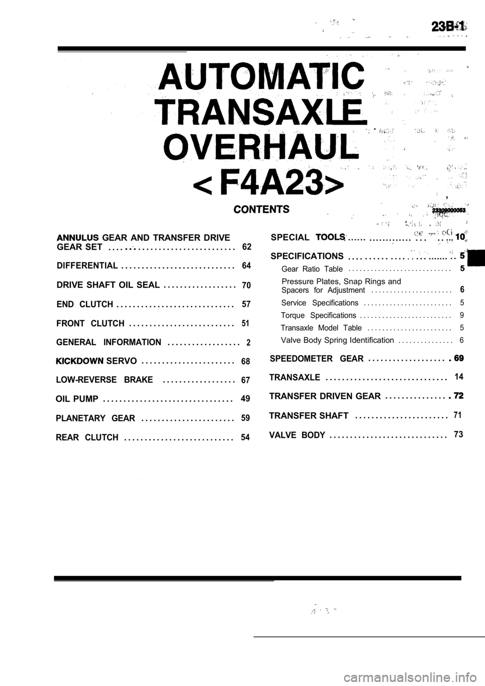
GEAR AND TRANSFER DRIVE
GEAR SET . . . .
. . . . . . . . . . . . . . . . . . . . . . . .62
DIFFERENTIAL
. . . . . . . . . . . . . . . . . . . . . . . . . . . .64
DRIVE SHAFT OIL SEAL . . . . . . . . . . . . . . . . . .70
END CLUTCH. . . . . . . . . . . . . . . . . . . . . . . . . . . . .57
FRONT CLUTCH. . . . . . . . . . . . . . . . . . . . . . . . . .51
GENERAL INFORMATION. . . . . . . . . . . . . . . . . .2
SERVO. . . . . . . . . . . . . . . . . . . . . . .68
LOW-REVERSE BRAKE. . . . . . . . . . . . . . . . . .67
OIL PUMP
. . . . . . . . . . . . . . . . . . . . . . . . . . . . . . . .49
PLANETARY GEAR
. . . . . . . . . . . . . . . . . . . . . . .59
REAR CLUTCH. . . . . . . . . . . . . . . . . . . . . . . . . . .54
SPECIAL. . . . . ... . . . . . . . . . . . .. . ...... ....
SPECIFICATIONS. . . . . . . . . . . . . .. .. . . ........ .
Gear Ratio Table. . . . . . . . . . . . . . . . . . . . . . . . . . . .
Pressure Plates, Snap Rings and
Spacers for Adjustment. . . . . . . . . . . . . . . . . . . . . .6
Service Specifications. . . . . . . . . . . . . . . . . . . . . . . .5
Torque Specifications. . . . . . . . . . . . . . . . . . . . . . . . .9
Transaxle Model Table. . . . . . . . . . . . . . . . . . . . . . .5
Valve Body Spring Identification . . . . . . . . . . . . . . .6
SPEEDOMETER GEAR. . . . . . . . . . . . . . . . . . .
TRANSAXLE. . . . . . . . . . . . . . . . . . . . . . . . . . . . . .14
TRANSFER DRIVEN GEAR . . . . . . . . . . . . . . .
TRANSFER SHAFT
. . . . . . . . . . . . . . . . . . . . . . .71
VALVE BODY. . . . . . . . . . . . . . . . . . . . . . . . . . . . .73
Page 1209 of 2103
AUTOMATIC TRANSAXLE
OVERHAUL Information
Torqueconverter
Front
clutch Rear
clutch
Oil pump
brake
I
TSB Revision
Transferdrive
Transferdriven gear
Differential
Page 1210 of 2103
A U T O M A T I C T R A N S A X L E
OVERHAUL General Information
6
II II
1.Torque converter
2.Front clutch
3.Rear clutch
4.Low-reverse brake
5.End clutch
6. servo
7. Transaxle control module
8. Torque converter clutch control valve 9. Torque converter clutch solenoid 10. Rear clutch exhaust valve
11. shift valve
12.Reducing valve13. Shift control solenoid valve
14. shift valve 15. End clutch valve
16. Torque converter control valve 17. Shift control solenoid valve
18. Shift control valve
19. N-D control valve
20.Regulator valve
21.Manual valve
22. Pressure control valve23.Oil pump24.Oil filter
25.Oil pan
26. Line relief valve 27. N-R control valve
28. Pressure control solenoid valve
Page 1211 of 2103
AUTOMATIC TRANSAXLE
OVERHAUL
TRANSAXLE MODEL TABLE
Transaxle modelSpeedometer gear ratio Final gear ratio Vehicle modelEngine
4.350
2.551
1.488 10 . 6 8 5
ItemsStandard value
Transfer idler gear bearing preload Nm
Input shaft end play mm (in.)
Transfer shaft end play mm (in.) Low-reverse brake end play mm (in.)
Differential case preload mm (in.)
End clutch snap ring clearance mm (in.)
Oil pump gear side clearance mm (in.)
Front clutch snap ring clearance mm (in.)
Rear clutch snap ring clearance mm (in.)
Output flange bearing end play mm (in.)
Differential pinion backlash mm (in.)
Pulse generator resistance
Pressure control solenoid valve resistance
Shift control solenoid valve resistance
Torque converter clutch solenoid resistance
(1.1)
,
,
at
, Approx. 3
Approx. 22 ohm at . .
Approx. 13 ohm
TSB Revision
Page 1212 of 2103

AUTOMATIC TRANSAXLE
OVERHAUL Specifications
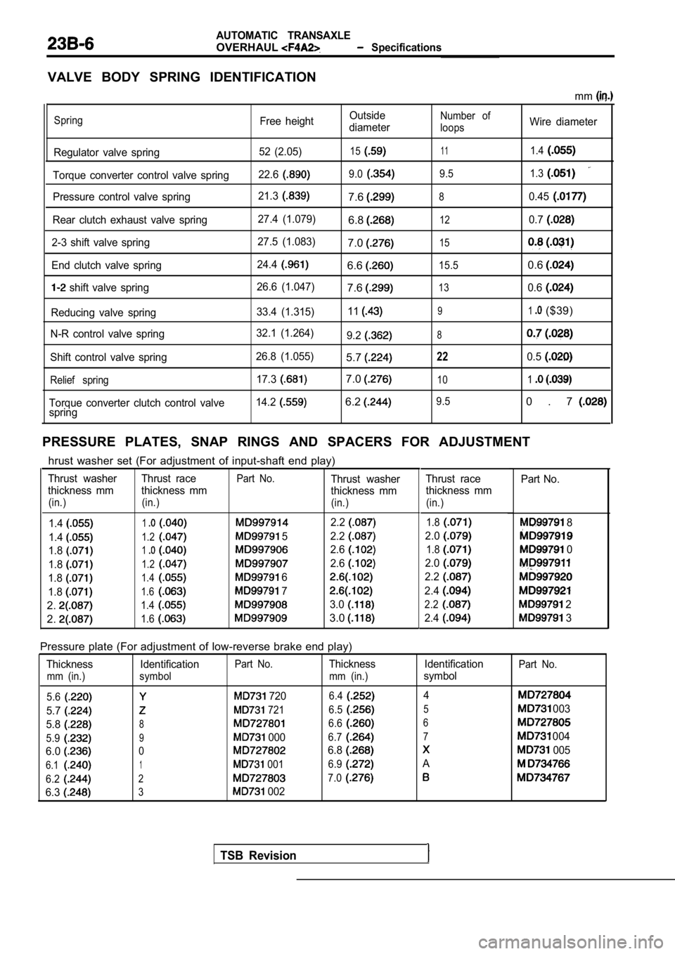
VALVE BODY SPRING IDENTIFICATION
mm
Spring
Regulator valve spring
Torque converter control valve spring
Pressure control valve spring
Rear clutch exhaust valve spring
2-3 shift valve spring
End clutch valve spring
shift valve spring
Reducing valve spring
N-R control valve spring
Shift control valve spring
Relief spring
Torque converter clutch control valve
spring Free height
52 (2.05)
22.6
21.3
27.4 (1.079)
27.5 (1.083)
24.4
26.6 (1.047)
33.4 (1.315)
32.1 (1.264)
26.8 (1.055) 17.3
14.2
Outside
diameter
15
9.0
7.6
6.8
7.0
6.6
7.6
11
9.2
5.7
7.0
6.2
Number of
loops
11
9.5
8
12
15
15.5
13
9
8
22
10
9.5
Wire diameter
1.4
1.3
0.45
0.7
0.6
0.6
1($39)
0.5
1
0 . 7
PRESSURE PLATES, SNAP RINGS AND SPACERS FOR ADJUSTM ENT
TSB Revision
hrust washer set (For adjustment of input-shaft end play)
Thrust washer Thrust racePart No.Thrust washer
thickness mm thickness mm thickness mm
(in.) (in.) (in.)
1.412.2
1.41.2 52.2
1.812.6
1.81.22.6
1.81.4 6
1.81.6 7
2.1.43.0
2.1.63.0
Thrust race
thickness mm
(in.)
Part No.
1.8 8
2.0
1.8 0
2.0
2.2
2.4
2.2 2
2.4
3
Pressure plate (For adjustment of low-reverse brake end play)
Thickness IdentificationPart No.Thickness
mm (in.) symbol mm (in.)
5.6
7206.4
5.7 721 6.5
5.886.6
5.99 0006.7
6.006.8
6.11 0016.9
6.227.0
6.33 002 Identification
symbol
4
5
6 7
A
Part No.
003
004
005
Page 1220 of 2103
4AUTOMATIC Transaxle
TRANSAXLE
16
18
16
1.Torque converter
2.Converter housing3.Gasket4.Oil pump5.O-ring6.Gasket7. Thrust washer 6. Front clutch assembly 9. Thrust race
10. Thrust bearing
11. Thrust washer
12. Rear clutch assembly
13.Spacer
14.Outer race
Differential16. Thrust bearing 17.Clutch hub
18. Thrust race
19. Thrust bearing 20. band
21. drum
22.Snap ring
23.Center support24.O-ring
25.Wave spring
26.Return spring
27.Pressure plate
28.Brake disc
29.Brake plate
30.Reaction plate
31. Reverse sun gear
32. Thrust bearing
33. Thrust race
34. Forward sun gear35.Planetary carrier
36. Thrust bearing
TSB Revision