Page 1548 of 2103

REAR AXLE Troubleshooting
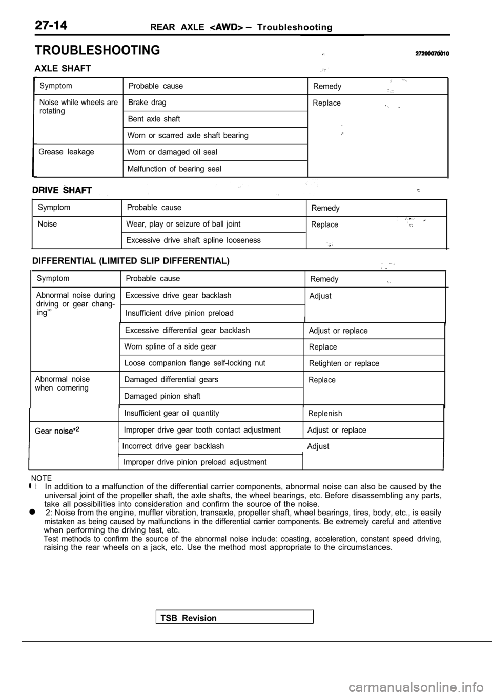
TROUBLESHOOTING
AXLE SHAFT
SymptomProbable causeRemedy
Noise while wheels are Brake drag
rotatingReplace
Bent axle shaft
Worn or scarred axle shaft bearing
Grease leakage Worn or damaged oil seal
Malfunction of bearing seal
Symptom
Noise Probable cause
Wear, play or seizure of ball joint Remedy
Replace
Excessive drive shaft spline looseness
DIFFERENTIAL (LIMITED SLIP DIFFERENTIAL)
SymptomProbable cause
Remedy
Abnormal noise during
driving or gear chang-Excessive drive gear backlash
Adjust
ing”’Insufficient drive pinion preload
II II
Abnormal noise
when cornering Excessive differential gear backlash
Worn spline of a side gear
Loose companion flange self-locking nut
Damaged differential gears
Damaged pinion shaft Adjust or replace
Replace
Retighten or replace
Replace
TSB Revision
Gear
Insufficient gear oil quantity
Improper drive gear tooth contact adjustmentReplenish
Adjust or replace
Incorrect drive gear backlash Adjust
I II
IImproper drive pinion preload adjustment
NOTE
l l:In addition to a malfunction of the differential carrier components, abnormal noise can also be caused by the
universal joint of the propeller shaft, the axle sh afts, the wheel bearings, etc. Before disassembling any parts,
take all possibilities into consideration and confi rm the source of the noise.
l 2: Noise from the engine, muffler vibration, transa xle, propeller shaft, wheel bearings, tires, body, etc., is easily
mistaken as being caused by malfunctions in the dif ferential carrier components. Be extremely careful and attentive
when performing the driving test, etc.
Test methods to confirm the source of the abnormal noise include: coasting, acceleration, constant speed
raising the rear wheels on a jack, etc. Use the met hod most appropriate to the circumstances.
driving,
Page 1550 of 2103
6REAR AXLE Service
REAR AXLE TOTAL BACKLASH
If the vehicle produces a booming sound due
to an of driving system, measure the rear
total backlash by the following procedures to see if the
carrier assembly requires removal.
1. Place the gearshift lever in theneutral position, apply
the parking brake and
up the vehicle.
Mating marks2.Manually turn the propeller. shaft as far as it
will go and make mating marks flange
dust cover and the differential carrier. ,
3.Manually turn the propeller shaft counterclockwise as far
as it will go and measure the of the mating!
marks.
Limit: 5 mm in.)
4.If the backlash exceeds’ the limit, remove the differential
carrier assembly (Refer to and adjust the back-
lash (Refer to
TSB Revision
GEAR OIL LEVEL
Remove the filler plug, check, the level. .
2.The oil is sufficient if hole.
Specified gear oil: ,
API classification
NOTEO v e r S A E
Under SAE
Page 1551 of 2103

REAR AXLE On-vehicle Service
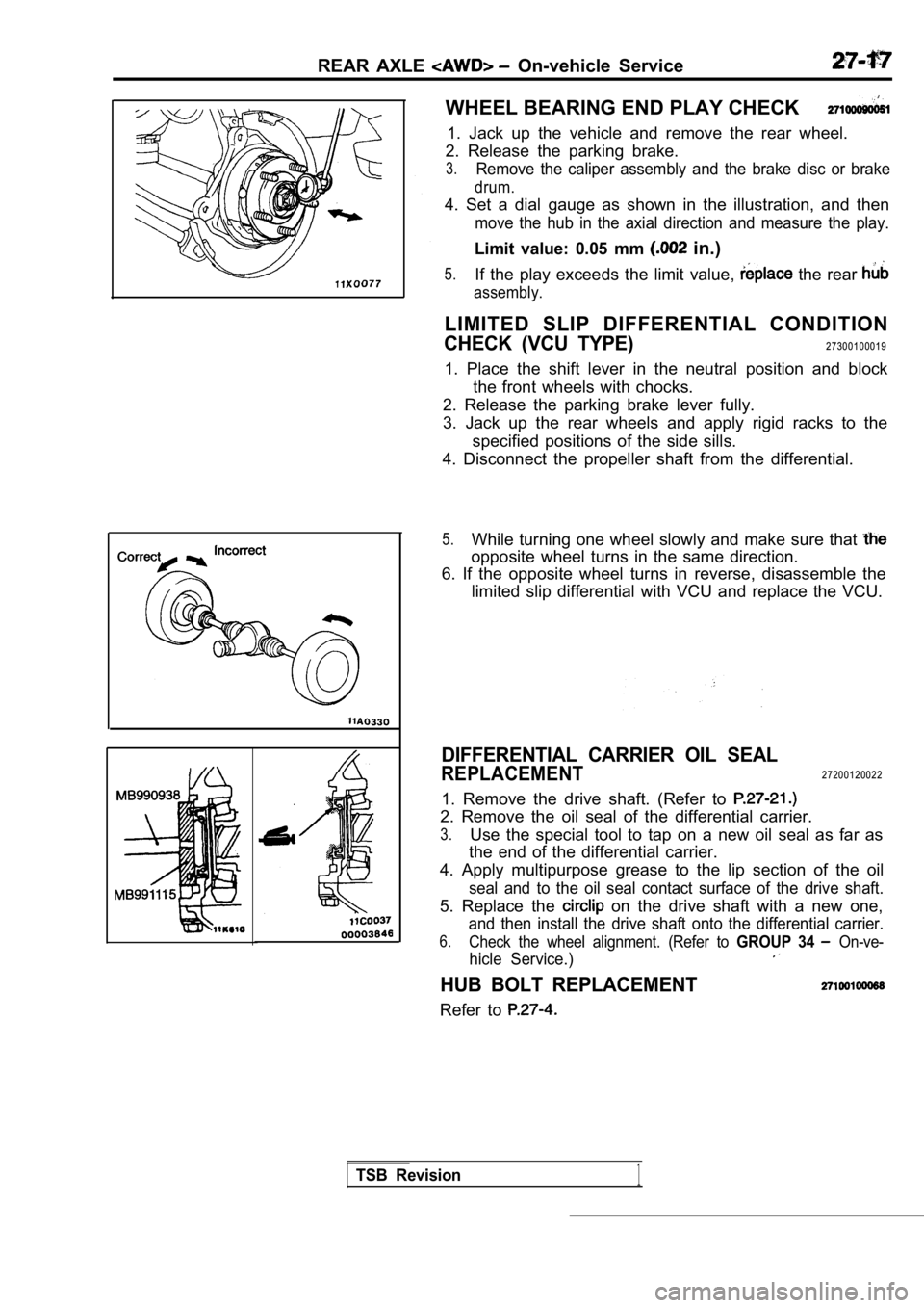
WHEEL BEARING END PLAY CHECK
1. Jack up the vehicle and remove the rear wheel.
2. Release the parking brake.
3.Remove the caliper assembly and the brake disc or b rake
drum.
4. Set a dial gauge as shown in the illustration, and then
move the hub in the axial direction and measure the play.
Limit value: 0.05 mm in.)
5.If the play exceeds the limit value, the rear
assembly.
LIMITED SLIP DIFFERENTIAL CONDITION
CHECK (VCU TYPE)27300100019
1. Place the shift lever in the neutral position an d block
the front wheels with chocks.
2. Release the parking brake lever fully.
3. Jack up the rear wheels and apply rigid racks to the
specified positions of the side sills.
4. Disconnect the propeller shaft from the differen tial.
5.While turning one wheel slowly and make sure that
opposite wheel turns in the same direction.
6. If the opposite wheel turns in reverse, disassem ble the
limited slip differential with VCU and replace the VCU.
DIFFERENTIAL CARRIER OIL SEAL
REPLACEMENT27200120022
1. Remove the drive shaft. (Refer to
2. Remove the oil seal of the differential carrier.
3.Use the special tool to tap on a new oil seal as fa r as
the end of the differential carrier.
4. Apply multipurpose grease to the lip section of the oil
seal and to the oil seal contact surface of the drive shaft.
5. Replace the on the drive shaft with a new one,
and then install the drive shaft onto the differential carrier.
6.Check the wheel alignment. (Refer to GROUP 34 On-ve-
hicle Service.)
HUB BOLT REPLACEMENT
Refer to
TSB Revision1
Page 1552 of 2103
REAR AXLE Rear Hub Assembly
REMOVAL AND INSTALLATION
OperationlDrive Shaft Removal (Refer to 1
Nm
7
8
49-59
NmNm
11
Removal steps
1. Rear wheel speed sensor
(Refer to GROUP WheelSpeed Sensor.)
2. Brake drum
3. Shoe and lever assembly
4. Caliper assembly (Refer to
5. Brake disc
6. Shoe and lining assembly (Refer to GROUP 36
Parking Brake
.)
0 0 0 0 4 0 4 6
7. Clip8. Parking brake cable
9. Rear hub assembly
10. Brake pipe connection
11. Dust seal
CautionThe rear hub assembly should not disassembled.
TSB Revision
Page 1555 of 2103
REAR AXLE Drive
2 7 1 0 0 3 3 0 0 2 3
REMOVAL AND INSTALLATION
Brake Line Bleeding with drum brakes>
(Refer to GROUP 36
On-vehicle Service.)
9871
I I10
,19
44118-1373385-99
11
with drum brakes>
11
9871. .,
Removal steps
1. Rear wheel speed sensor
2. Caliper assembly (Refer to 3. Brake disc
4. Brake drum
5. Shoe and lining assembly (Refer to
GROUP 36
Parking Brake.)6. Shoe and lever assembly
7. Clip8. Parking brake cable
9. Brake pipe connection
10. Shock absorber connection Trailing arm connection12. Lower arm connection
13. Toe control armball joint andknuckle connection(Refer to 14. pin 15. Drive shaft nut16. Washer
17. Differential mount support
18. Drive shaft
19.
Caution1.For vehicles with ABS, careful not to damagedrive shaft rotor.2.l : Indicates parts should be temporarily and then fully tightened the on the
ground in the unladen condition.
TSB Revision
Page 1563 of 2103

REAR AXLE Differential Carrier
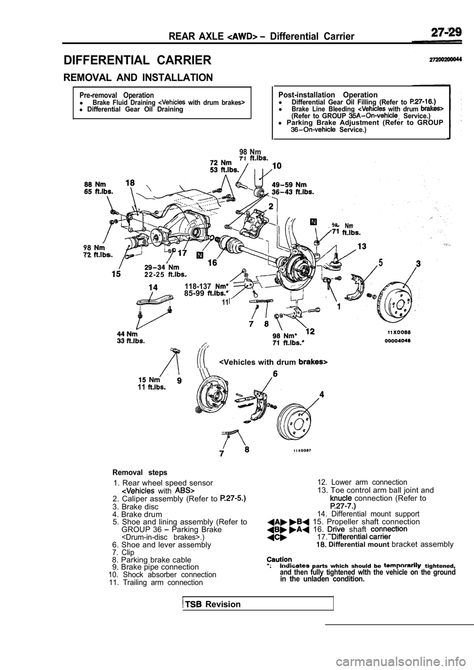
DIFFERENTIAL CARRIER
REMOVAL AND INSTALLATION
Pre-removal OperationlBrake Fluid Draining with drum brakes>l Differential Gear Oil Draining
98 Nm
Post-installation OperationlDifferential Gear Oil Filling (Refer to lBrake Line Bleeding with drum (Refer to GROUP Service.)l Parking Brake Adjustment (Refer to GROUP Service.)
98
2 2 - 2 5
118-13785-99
11
5
11
Removal steps
1. Rear wheel speed sensor
with 2. Caliper assembly (Refer to
3. Brake disc
4. Brake drum
5. Shoe and lining assembly (Refer to
GROUP 36
Parking Brake.)6. Shoe and lever assembly7. Clip8. Parking brake cable9. Brake pipe connection
10. Shock absorber connection
11. Trailing arm connection 12. Lower arm connection
13. Toe control arm ball joint and
connection (Refer to
14. Differential mount support 15. Propeller shaft connection 16. shaft 17. Differential mount
bracket assembly
parts which should be tightened,and then fully tightened wlth the vehicle on the gr oundin the unladen condition.
Revision
Page 1623 of 2103

REAR SUSPENSION Rear Suspension
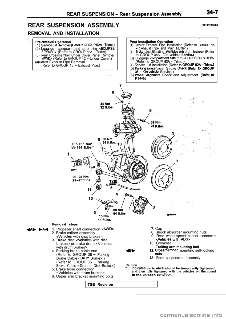
REAR SUSPENSION ASSEMBLY
REMOVAL AND INSTALLATION
Operation
(1)
(2) Lug agecompartment side trim SP (Refer to GROUP Trims)(3) Rear Crossmember Under Cover Panel Removal (Refer to GROUP 42 Under Cover.) Exhaust Pipe Removal(Refer to GROUP 15 Exhaust Pipe.)
3410033004
Post-installation Operation Center Exhaust Pipe Installation (Refer to GROUP 15Exhaust Pipe and Main Muffler,)(2) Line Bleeding drum (Referto GROUP On-vehicle (3) Luggage trim (Refer to GROUP Trims.
(4) Service Lid Installation (Refer to
(5) Brake Lever Stroke (Refer GROUP Service.)
(6) Check and Adjustment .
6
,
137-15799-114
.
l. .
3
Removal steps
11
1. Propeller shaft connection 2. Brake caliper assembly with disc brakes>
3. Brake disc with disc
brakes> or brake drum
with drum brakes>
4. Parking brake cable end
(Refer to GROUP 36
ParkingBrake Cable Brake>.)
(Refer to GROUP 36
ParkingBrake Cable .)5. Brake hose connection
6. Upper arm bracket mounting bolts
Cap
8. Shock absorber mounting nuts
9. Rear wheel-speed sensor connector with 10. Grommet11. Trailing arm mounting bolt
12. mounting self-locking
13. Rear suspension assembly
Cautionindicatesparts should temporarily tightened,and then fully tightened with the vehicles on thegr oundin the unladen
TSB Revision
Page 1637 of 2103
SERVICE BRAKES
CONTENTS
BASIC BRAKE SYSTEM. . . . . . . . . . . . . . . . . . . . . . . . . . . . . . . . . . . . . . . . . . . . . . . .
ANTI-LOCK BRAKING SYSTEM (ABS) . . . . . . . . . . . . . . . . . . . . . . . . . . .358
ANTI-LOCK BRAKING SYSTEM (ABS) . . . . . . . . . . . . . . . . . . . . . . . . . . .