1990 MITSUBISHI SPYDER brake sensor
[x] Cancel search: brake sensorPage 492 of 2103
ENGINE (NON-TURBO)> Troubleshooting
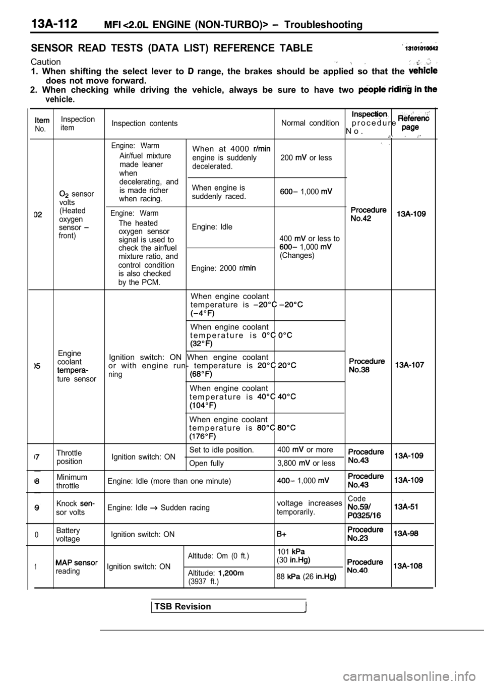
SENSOR READ TESTS (DATA LIST) REFERENCE TABLE
Caution
1. When shifting the select lever to range, the brakes should be applied so that the
does not move forward.
2. When checking while driving the vehicle, always be sure to have two
vehicle.
Inspection
No.itemInspection contents
Normal conditionp r o c e d u r e
N o .
Engine: WarmWhen at 4000 Air/fuel mixture
engine is suddenly 200 or less
made leaner
decelerated.when
decelerating, and
sensor is made richer
When engine is 1,000
voltswhen racing.
suddenly raced.
(Heated
oxygenEngine: Warm
The heatedsensoroxygen sensor Engine: Idlefront)signal is used to
400 or less to
check the air/fuel
1,000
mixture ratio, and (Changes)
control condition is also checked Engine: 2000
by the PCM.
When engine coolant
t e m p e r a t u r e i s
When engine coolant
t e m p e r a t u r e i s
Engine
coolantIgnition switch: ON When engine coolant
or with engine run- temperature is
ture sensorning
When engine coolant
t e m p e r a t u r e i s
When engine coolant
t e m p e r a t u r e i s
Throttle Set to idle position.
400 or more
position Ignition switch: ON
Open fully 3,800
or less
Minimum
throttle Engine: Idle (more than one minute) 1,000
KnockCode
sor voltsEngine: Idle Sudden racingvoltage increases
temporarily.
0Battery
voltage Ignition switch: ON
101
1
Altitude: Om (0 ft.)
reading
Ignition switch: ON (30Altitude:
(3937 ft.)88 (26
TSB Revision
Page 619 of 2103
ENGINE (TURBO)
AND ENGINE>
Caution
1. Always apply the brakes when shifting the select or lever to ran&, or vehicle will
forward.
2. Driving tests always need another personnel.
NOTE
In a new vehicle [driven approximately 500 km (300 mile) or less], the volume air sensor output
is sometimes 10 higher than the standard frequency.
The injector drive time represents the time when the cranking speed is at 250 or below when the
supply voltage is 11 V.
In a new vehicle [driven approximately 500 km (300 mile) or less], the injector drive time is sometimes
longer than the standard time.
Fuel is injected into all cylinders simultaneously.
In a new vehicle [driven approximately km (300 mile) or less], the step of the stepper mo tor is sometimes
30 steps greater than the standard value.
If the throttle position sensor voltage rises 100 from the voltage when the engine is at idle and th e
closed throttle position switch turns from on to of f at this time, the sensors are normal. If the throttle position
sensor voltage rises 100
from the voltage when the engine is at idle, the t hrottle valve opens, and the
closed throttle position switch turns from on to of f at this, time, the sensors should be adjusted.
Item Inspection
No.item
Inspection contents Normal contentsInspection
procedure page
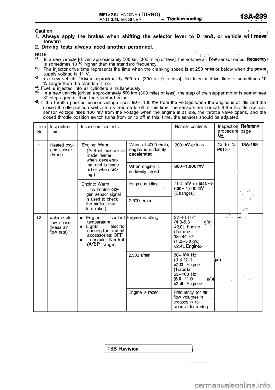
11HeatedEngine: WarmWhen at 4000 200 or Code No.
gen sensor engine is suddenly(Air/fuel mixture is 30
(Front)
made leaner
when decelerat- ing, and is made
richer when
When engine is
suddenly raceding.)
Engine: Warm Engine is idling
400 or
(The heated 1,000 ,gen sensor signal(Changes)
is used to check
2,500
the air/fuel mix-
ture ratio.)
Volume airl Engine coolant Engine is idling 22-46 Hz’
flow sensortemperature(4.3-5.3 g/s)
(Mass airl
Lights,electric
flow rate) cooling fan and all Engine
accessories: OFF(Turbo)>
l Transaxle: Neutral Hz
range)(1 g/s)
2,500
Engine is raced
Hz
(9.8-12.1
Engine,
Hz ,
Engine>
Frequency (or air
flow volume) in
creases
re- ,
sponse to racing.
TSB Revision
Page 721 of 2103
INTAKE AND EXHAUST Intake Manifold Engine
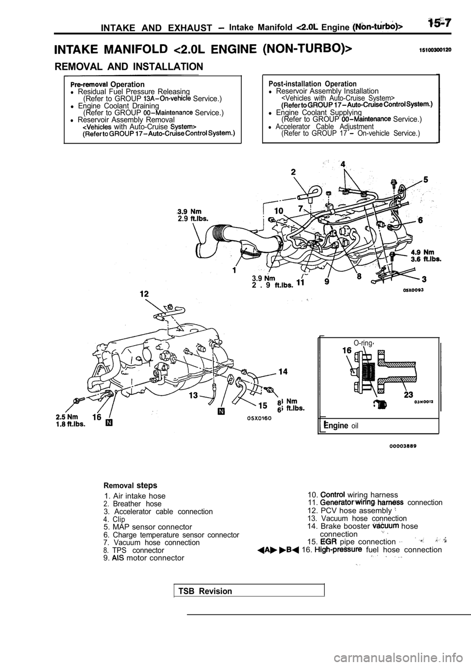
REMOVAL AND INSTALLATION
Operationl Residual Fuel Pressure Releasing(Refer to GROUP Service.)l Engine Coolant Draining(Refer to GROUP Service.)l Reservoir Assembly Removal with Auto-Cruise
2.9
Post-installation Operationl Reservoir Assembly Installation
l Engine Coolant Supplying (Refer to GROUP Service.)l Accelerator Cable Adjustment (Refer to GROUP 17 On-vehicle Service.)
3.92 . 9
O-ring
Engineoil
Removalsteps
1. Air intake hose2.Breather hose
3. Accelerator cable connection
4. Clip5. MAP sensor connector
6. Charge temperature sensor connector
7. Vacuum hose connection
8.TPS connector9. motor connector 10.
wiring harness11. connection
12. PCV hose assembly 13. Vacuum hose connection14. Brake booster hose
connection
15. pipe connection
16. fuel hose connection
TSB Revision
Page 725 of 2103
INTAKE AND EXHAUST Intake Manifold Engine
INTAKE MANIFOLD ENGINE (TURBO)>15100300298
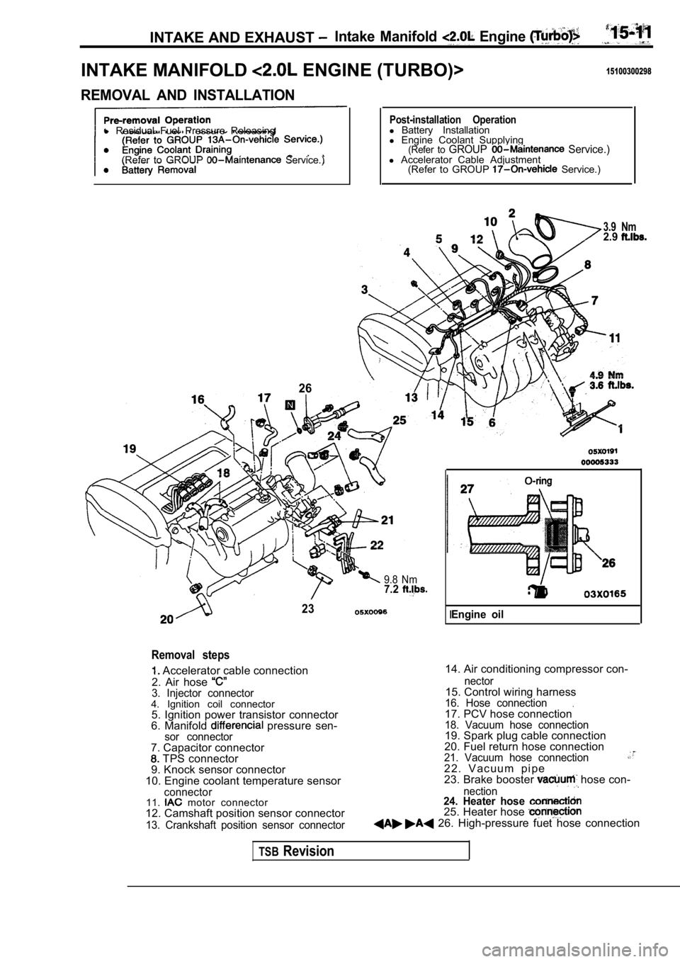
REMOVAL AND INSTALLATION
l Residual Fuel Pressure Releasing
(Refer to GROUP
Service.)
26
Post-installation Operationl Battery Installation
l Engine Coolant Supplying
(Refer to GROUP Service.)l Accelerator Cable Adjustment
(Refer to GROUP Service.)
3.9 Nm2.9
9.8 Nm7.2
23
Removal steps
Accelerator cable connection
2. Air hose
3. Injector connector4. Ignition coil connector 5. Ignition power transistor connector
6. Manifold
pressure sen-sor connector
14. Air conditioning compressor con-
7. Capacitor connector
TPS connector
9. Knock sensor connector
10. Engine coolant temperature sensor
connector11. motor connector
12. Camshaft position sensor connector
13. Crankshaft position sensor connector nector
15. Control wiring harness16. Hose connection.17. PCV hose connection18. Vacuum hose connection19. Spark plug cable connection
20. Fuel return hose connection
21. Vacuum hose connection2 2 . V a c u u m p i p e
23. Brake booster hose con-
nection24. Heater hose 25. Heater hose 26. High-pressure fuet hose connection
IEngine oil
TSBRevision
Page 728 of 2103
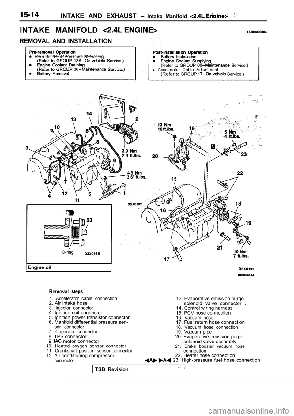
INTAKE AND EXHAUST Intake Manifold
INTAKE MANIFOLD
REMOVAL AND INSTALLATION
l Residual Fuel Pressure Releasing
(Refer to GROUP
Service.) (Refer to GROUP Service.)
l Accelerator Cable Adjustment
(Refer to GROUP
Service.)
2.9
4.9 Nm 3.6’ 15
O-ring
Engine oilI
18
10 Nm7
Removal
1. Accelerator cable connection2. Air intake hose3. Injector connector4. Ignition coil connector
5. Ignition power transistor connector
6. Manifold differential pressure sen-
sor connector
7. Capacitor connector
8. TPS connector
9. motor connector
10. Heated oxygen sensor connector
11. Crankshaft position sensor connector12. Air conditioning compressor
connector
13. Evaporative emission purge
solenoid valve connector .
14. Control wiring harness
15. PCV hose connection
16. Vacuum hose17. Fuel return hose connection18. Vacuum hose connection
19. Vacuum pipe
20. Evaporative emission purge solenoid valve assembly
21. Brake booster vacuum hose
connection22. Heater hose connection 23. High-pressure fuel hose connection
TSB Revision
Page 759 of 2103
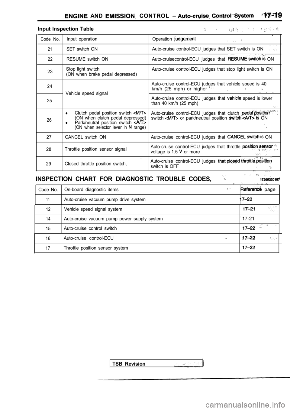
AND CONTROL
Input Inspection Table
.
Code No.Input operation Operation
21SET switch ONAuto-cruise control-ECU judges that SET switch is O
N
22RESUME switch ON Auto-cruisecontrol-ECU judges that ON
23 Stop light switch
(ON when brake pedal depressed) Auto-cruise control-ECU judges that stop light swit
ch is ON
24
25
26Auto-cruise control-ECU judges that vehicle speed i s 40
km/h (25 mph) or higher ,Vehicle speed signal
Auto-cruise control-ECU judges that speed is lower
than 40 km/h (25 mph)
lClutch pedal position switch Auto-cruise control-ECU judges that clutch (ON when clutch pedal depressed) Park/neutral position switch switch or park/neutral position ONl(ON when selector lever in range)
27 CANCEL switch ON Auto-cruise control-ECU judges that
ON
28 Throttle position sensor signal Auto-cruise control-ECU judges that throttle
voltage is 1.5 or more
29Closed throttle position switch,Auto-cruise control-ECU judges
switch is OFF
INSPECTION CHART FOR DIAGNOSTIC TROUBLE CODES,
Code No.
On-board diagnostic items page
11Auto-cruise vacuum pump drive system
12
14
15
Vehicle speed signal system
Auto-cruise vacuum pump power supply system
Auto-cruise control switch
17-21
.
16
17
Auto-cruise control-ECU
Throttle position sensor system
TSB Revision
Page 772 of 2103
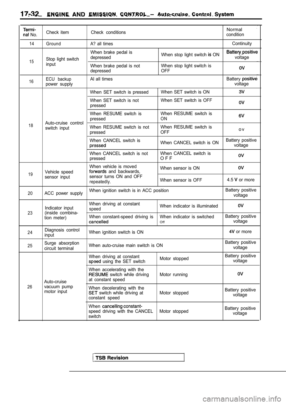
E N G I N E EMISSION CONTROL Auto-cruise Control
No.
14
15
Check item
Ground
Stop light switch
inputCheck conditions
A? all times
When brake pedal is
depressed
When brake pedal is not
depressed
Normal
condition
Continuity
When stop light switch ON voltage
When stop light switch is
OFF
16
18
19ECU backupAl all times Battery
power supply voltage
When SET switch is pressed When SET switch is ON
When SET switch is notWhen SET switch is OFF
pressed
When RESUME switch is When RESUME switch is
pressed
ONAuto-cruise control
switch input When RESUME switch is not
When RESUME switch is
pressed OFF
o v
When CANCEL switch is
When CANCEL switch is ONBattery positivevoltage
When CANCEL switch is not When CANCEL switch is
pressed
O F F
When vehicle is moved When sensor is ON
Vehicle speed and backwards,
sensor input sensor turns ON and OFF
repeatedly.When sensor is OFF
4.5 or more
20ACC power supplyWhen ignition switch is in ACC position
Battery positive
voltage
23
24
Indicator input
(inside combina-
tion meter)
Diagnosis control
input When driving at constantspeedWhen indicator is illuminated
When constant-speed driving is When indicator is swi
tchedBattery positive
Offvoltage
When ignition switch is ON
or more
25
26Surge absorption
circuit terminal
Auto-cruise
vacuum pump motor input When auto-cruise main switch is ON
When driving at constant
Motor stopped
using the SET switch
When accelerating with the
switch while driving Motor running
at constant speed
When decelerating with the
switch while driving at Motor stopped
constant speed
When
speed driving with the CANCEL Motor stopped
switch Battery positive
voltage
Battery positive voltage
Battery positivevoltage
Battery positive voltage
Page 1020 of 2103
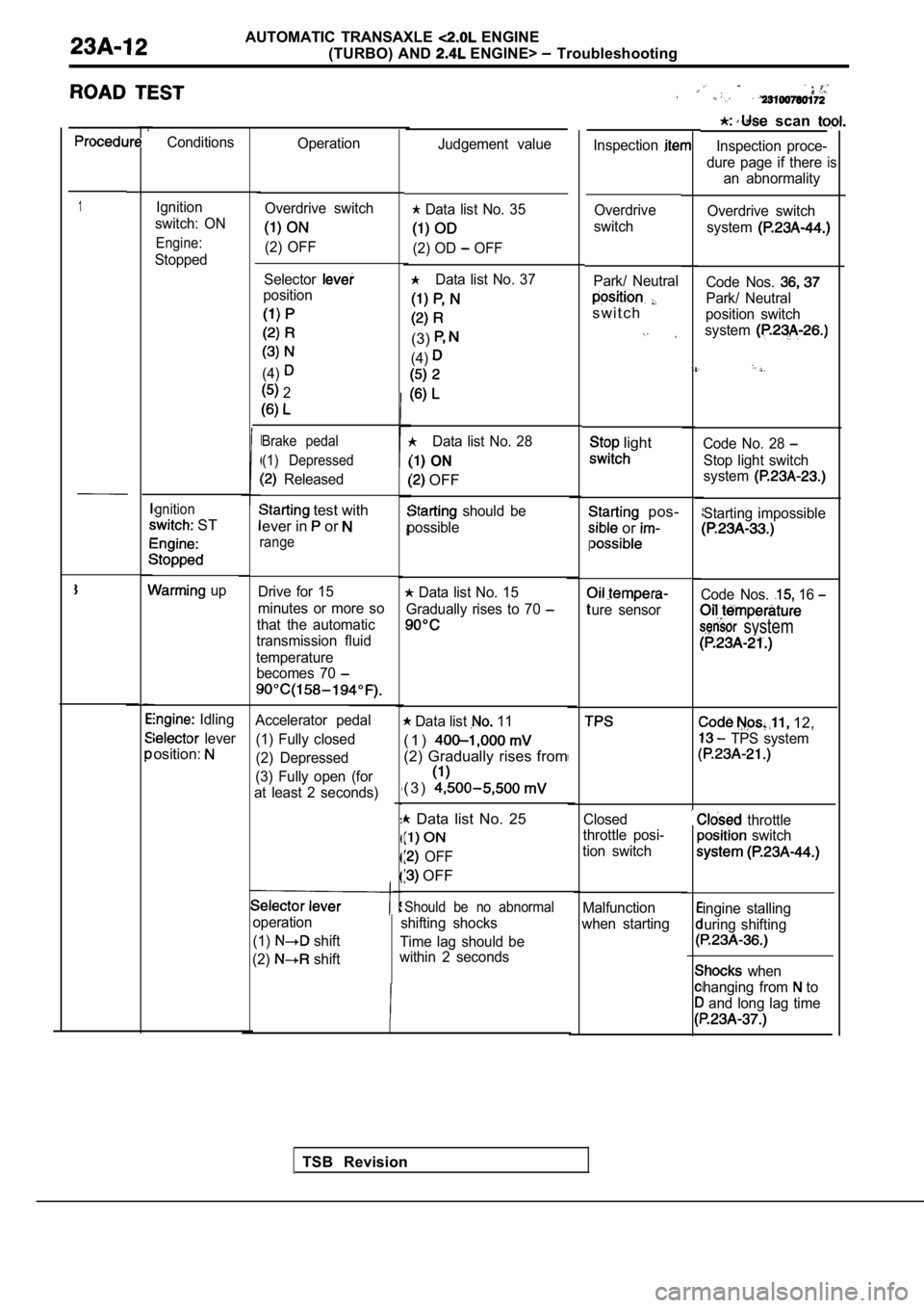
AUTOMATIC TRANSAXLE ENGINE
(TURBO) AND
ENGINE> Troubleshooting
scan
Inspection proce-
dure page if there an abnormality
is
Conditions Operation
Inspection
1Ignition
switch: ON
Engine:
Stopped
gnition
ST
up
Idling
lever
osition:
Judgement value
Overdrive switch
system
Code Nos.
Park/ Neutral
position switch
system
Code No. 28
Stop light switch
system
Starting impossible
Code Nos. 16
system
12,
TPS system
throttle switch
ingine stalling
uring shifting
when
hanging from
to
and long lag time
Overdrive switch
(2) OFF
Data list No. 35
(2) OD OFF
Data list No. 37
(3)
(4)
Data list No. 28
ON
OFF
should be
possible Overdrive
switch
Selector
position
(4)
2
Park/ Neutral
s w i t c h
Brake pedal (1) Depressed
Released
light
pos-
or
I
ure sensor
test with
ever in
or
range
Drive for 15
minutes or more so
that the automatic
transmission fluid
temperature becomes 70 Data list No. 15
Gradually rises to 70
Accelerator pedal
(1) Fully closed
(2) Depressed
(3) Fully open (for
at least 2 seconds) Data list 11
( 1 )
(2) Gradually rises from
( 3 )
Data list No. 25
OFF
OFF
Closed
throttle posi-
tion switch
Should be no abnormal
shifting shocks
Time lag should be
within 2 seconds Malfunction
when starting
operation
(1)
shift
(2)
shift
TSB Revision