Page 1712 of 2103
On-vehicle. Service
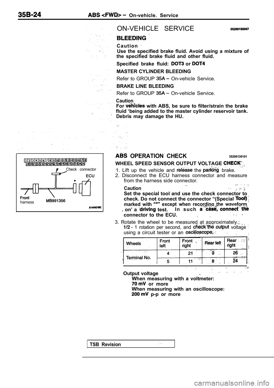
Check connector
l
harness
ON-VEHICLE SERVICE
C a u t i o n
Use the specified brake fluid. Avoid using a mixture of
the specified brake fluid and other fluid.
Specified brake fluid:
or
MASTER CYLINDER BLEEDING
Refer to GROUP
On-vehicle Service.
BRAKE LINE BLEEDING
Refer to GROUP
On-vehicle Service.
Caution
For with ABS, be sure to filter/strain the brake
fluid ‘being added to the master cylinder reservoir tank.
Debris may damage the HU.
OPERATION CHECK35200130101
WHEEL SPEED SENSOR OUTPUT VOLTAGE
1. Lift up the vehicle and the brake.
2. Disconnect the ECU harness connector and measure from the harness side connector.
Caution
Set the special tool and use the check connector to
check. Do not connect the connector “(Special
marked with except when recording the waveform
. on’ a test. I n s u c h
connector to the ECU.
3. Rotate the wheel to be measured at approximately
.;
1 rotation per second, and voltage
using a circuit tester or an
Output voltage.
When measuring with a voltmeter:
or more
When measuring with an oscilloscope:
p-p or more
TSB Revision
Page 1720 of 2103
ABS Master Cylinder and Brake Booster
MASTER CYLINDER AND BRAKE BOOSTER
REMOVAL AND INSTALLATION
(Refer to GROUP Master Cylinder and Brake Booster.)
MASTER CYLINDER
DISASSEMBLY AND REASSEMBLY
. .
,
13
TSBRevision
19 14
15
Master cylinder kit
Brake fluid:
steps
Reservoir bracket2.Reservoir hose3. Reservoir cap assembly4.Diaphragm5.Reservoir cap6.Filter7. Brake fluid level sensor8,Float9.Reservoir10.Pin
Retainer12.Connector13.Grommet14. Piston stopper bolt15.Gasket
16. Piston stopper ring
17. Primary piston assembly
18. piston assembly19. Master cylinder body
CautionDo not disassemble the primary and secondary piston
assembly.
Page 1726 of 2103
ABS W h e e l S p e e d S e n s o r
WHEEL SPEED SENSOR
REMOVAL AND INSTALLATION
Operationl Splash Shield Removal
Installation Splash Shield
Front ,
Rear 49-59
74-66
4
Front wheel speed sensor removalsteps
1. Clip 2. Front wheel speed sensor Front ABS rotor removal3. Drive shaft
(Refer to GROUP 26 Drive
Shaft.)
Rear wheel speed sensor removal
4. Rear wheel speed sensor
Rear ABS rotor removal steps
5. Caliper assembly
6. Brake disc
7. Shoe and lining assembly
(Refer to GROUP 36 Parking
Brake Drum.)8. Rear hub assembly
9. Rear ABS rotor
NOTEThe front ABS rotor, integrated with the drive shaf t, can not be dis-assembled.
TSB Revision
Page 1731 of 2103
CONTENTS
ABS-ECU. . . . . . . . . . . . . . . . . . . . . . . . . . . . . . . . .31 SERVICE SPECIFICATIONS . . . . . . . . . . . . . . . . . 3
GENERAL INFORMATION2SPECIAL TOOLS. . . . . . . . . . . . . . . . . . . . . . . . . . .3. . . . . . . . . . . . . . . . . .
G-SENSOR2 9. . . . . . . . . . . . . . . . . . . . . . . . . . . . . . .4
ON-VEHICLE SERVICE . . . . . . . . . . . .
. . . . 21WHEEL SPEED . . . . . . . . . . . . . . . . . .
ABS Operation Check . . . . . . . . . . . . . . . . . . . . . . . 21
Refer to for the following items.
BRAKE PEDAL
FRONT DISC BRAKE
LUBRICANTS
REAR DISC BRAKE
REAR DRUM BRAKE SHOE
REAR DRUM BRAKE WHEEL CYLINDER
ON-VEHICLE SERVICE
Brake Booster Operating Test
Brake Drum Inside Diameter Check
with Rear Drum Brakes>
Brake Fluid Level Sensor Check
Brake Lining and Brake Drum
Contact Check
Brake Lining Thickness Check Brake Pedal Check and Adjustment
Check Valve Operation Check
Front Brake Disc Run-out Check
Brake
Front Check and
Front Check
Proportioning Valve Test
Rear Brake Check
Rear Brake Disc Run-out Correction
Rear Brake Disc Thickness Check
Rear Disc Brake Pad Check and Replacement
Stop Light Switch Check
Refer to GROUP for the following items.
H Y D R A U L I C U N I T
MASTER CYLINDER AND BRAKE BOOSTER
PROPORTIONING VALVE
ON-VEHICLE
,
Bleeding,
Page 1751 of 2103
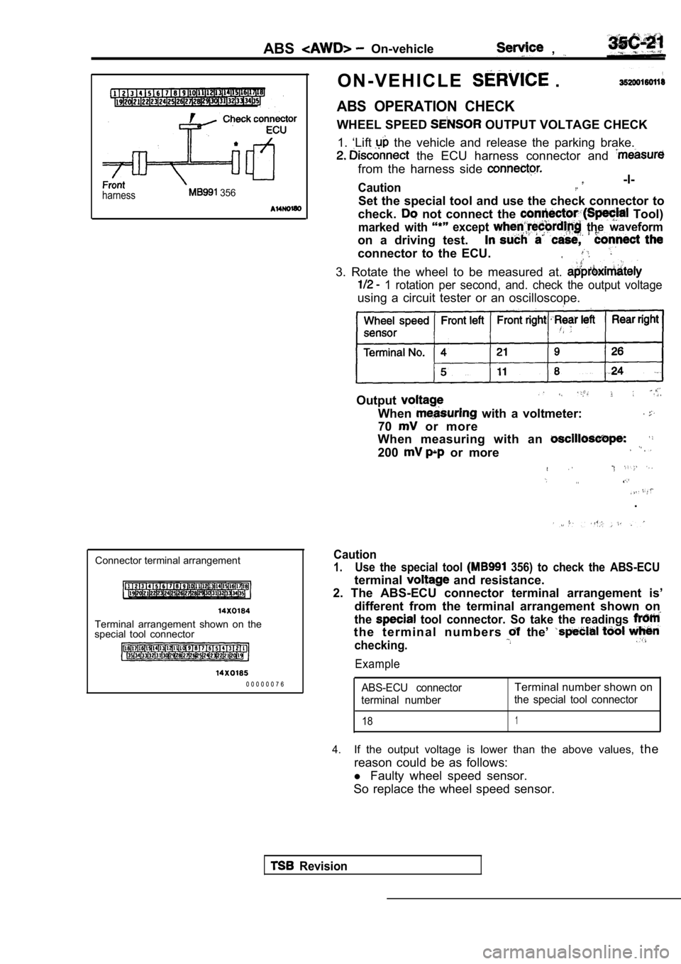
harness 356
ABSOn-vehicle ,
O N - V E H I C L E .
ABS OPERATION CHECK
WHEEL SPEED OUTPUT VOLTAGE CHECK
1. ‘Lift
the vehicle and release the parking brake.
the ECU harness connector and
from the harness side
Caution -I-,.
Set the special tool and use the check connector to
check.
not connect the Tool)
marked with except the waveform
on a driving test.
connector to the ECU.
3. Rotate the wheel to be measured at.
1 rotation per second, and. check the output volta ge
using a circuit tester or an oscilloscope.
Wheel speed Front left
Front right left
Output
When with a voltmeter:
70
or more
When measuring with an
200 or more
. .
.
Connector terminal arrangement
Terminal arrangement shown on the
special tool connector
0 0 0 0 0 0 7 6
Caution
1.Use the special tool 356) to check the ABS-ECU
terminal and resistance.
2. The ABS-ECU connector terminal arrangement is’
different from the terminal arrangement shown on
the tool connector. So take the readings
t h e t e r m i n a l n u m b e r s the’
checking.
Example
ABS-ECU connectorTerminal number shown on
terminal number the special tool connector
181
4.If the output voltage is lower than the above value
s, the
reason could be as follows:
l Faulty wheel speed sensor.
So replace the wheel speed sensor.
Revision
Page 1794 of 2103
STEERING Power Steerina
R e m o v a l s t e p s
7.Stay (L.H.)
6.Stay (R.H.)
Caution
9. Centermember assembly
10. Clamp
11. Gear box assembly12.Return tube
The fasteners marked l be temporarily tightened
before they are finally tightened once the total we ight of
the engine has been placed on the
body.
REMOVAL SERVICE POINTS
BRAKE FLUID RESERVOIR ASSEMBLY
REMOVAL
Disconnect the brake fluid level sensor connector a nd remove
the brake fluid reservoir assembly from the dash pa nel with
the hose still attached.
NOTE
Place the removed reservoir where it
will not be a hindrance
power steering gear box, and
REMOVAL
Disconnect the and remove the
compressor from the
the hose
attached.
NOTE
Place the removed A/C compressor in a place where i t will
not be a hindrance when removing and installing the brake
fluid reservoir assembly, and tie it with a cord.
Caution
Do not damage the joint between the NC hose and the
pipe.
TSB Revision. .
Page 1822 of 2103
STEERING Power Steering Hoses Engine (Turbo) and Engine>
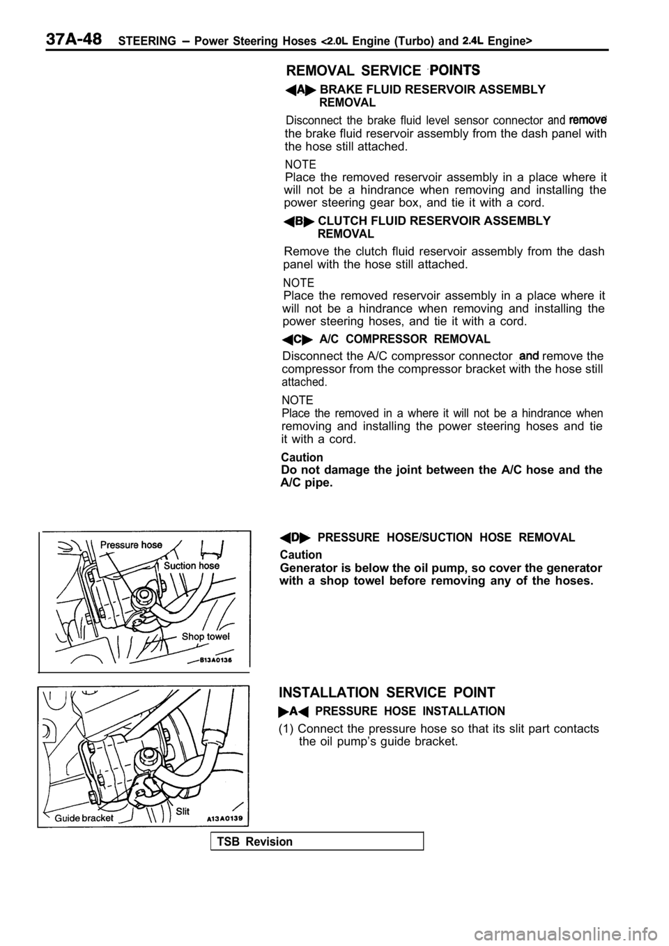
REMOVAL SERVICE
BRAKE FLUID RESERVOIR ASSEMBLY
REMOVAL
Disconnect the brake fluid level sensor connector and
the brake fluid reservoir assembly from the dash panel with
the hose still attached.
NOTE
Place the removed reservoir assembly in a place whe re it
will not be a hindrance when removing and installin g the
power steering gear box, and tie it with a cord.
CLUTCH FLUID RESERVOIR ASSEMBLY
REMOVAL
Remove the clutch fluid reservoir assembly from the dash
panel with the hose still attached.
NOTE
Place the removed reservoir assembly in a place whe re it
will not be a hindrance when removing and installin g the
power steering hoses, and tie it with a cord.
A/C COMPRESSOR REMOVAL
Disconnect the A/C compressor connector remove the
compressor from the compressor bracket with the hos e still
attached.
NOTE
Place the removed in a where it will not be a hindrance when
removing and installing the power steering hoses an d tie
it with a cord.
Caution
Do not damage the joint between the A/C hose and the
A/C pipe.
PRESSURE HOSE/SUCTION HOSE REMOVAL
Caution
Generator is below the oil pump, so cover the gener ator
with a shop towel before removing any of the hoses.
INSTALLATION SERVICE POINT
PRESSURE HOSE INSTALLATION
(1) Connect the pressure hose so that its slit part contacts
the oil pump’s guide bracket.
TSB Revision
Page 2072 of 2103
HEATER, AIR
AND VENTILATIONCompressor’ and Pulley Engine (Turbo) and
INSTALLATION
COMPRESSOR INSTALLATION
If a new compressor is installed, first adjust the amount of
oil according to the procedures described below, an d then
install the compressor.
(1)Measure the amount (x of oil within the
removed compressor.
(2) Drain (from the new compressor) the amount of o il calcu-
lated according to the following formula, and then install
then new compressor.
New compressor oil amount
170
(1) (y indicates the amount of oil in the
refrigerant line, the condenser, the evaporator
. .
R E M O V A L S E R V I C E P O I N T S
FLUID
Disconnect the brake fluid level sensor connector a nd, remove
the brake fluid reservoir from the compressor
the hose still attached.
NOTE
Place the removed brake fluid reservoir in where
it will not be a hindrance when removing and instal ling the
A/C compressor, and tie it
cord.
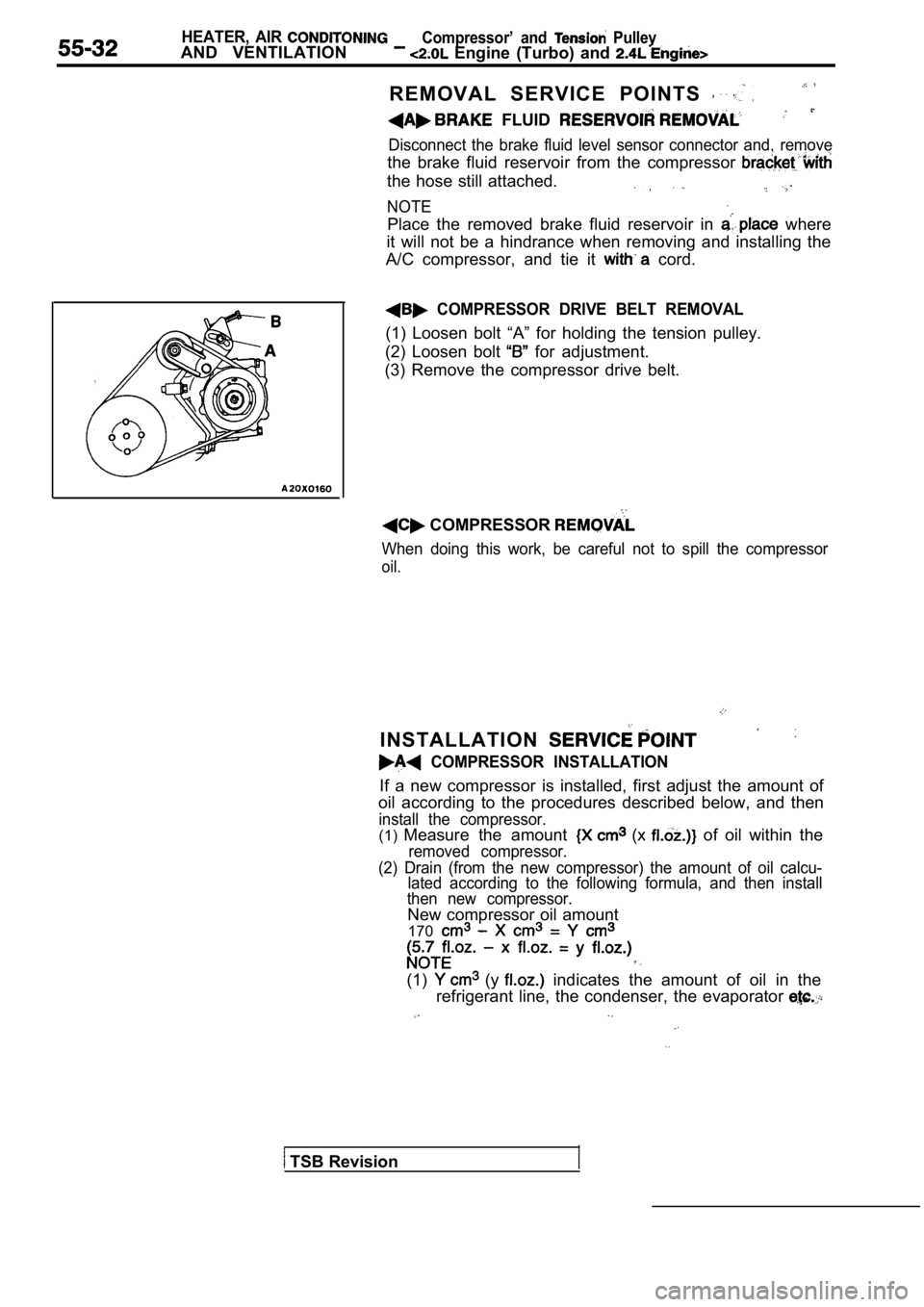
COMPRESSOR DRIVE BELT REMOVAL
(1) Loosen bolt “A” for holding the tension pulley.
(2) Loosen bolt
for adjustment.
(3) Remove the compressor drive belt.
COMPRESSOR
When doing this work, be careful not to spill the c ompressor
oil.
TSB Revision