1990 MITSUBISHI SPYDER brake sensor
[x] Cancel search: brake sensorPage 1051 of 2103
![MITSUBISHI SPYDER 1990 Service Repair Manual AUTOMATIC TRANSAXLE
ENGINE (TURBO) AND ENGINE,
INSPECTION PROCEDURE 14
Poor accelerationI
[Comment]l Malfunction of clutches and brakesWhile driving, acceleration is poor even if MITSUBISHI SPYDER 1990 Service Repair Manual AUTOMATIC TRANSAXLE
ENGINE (TURBO) AND ENGINE,
INSPECTION PROCEDURE 14
Poor accelerationI
[Comment]l Malfunction of clutches and brakesWhile driving, acceleration is poor even if](/manual-img/19/57345/w960_57345-1050.png)
AUTOMATIC TRANSAXLE
ENGINE (TURBO) AND ENGINE,
INSPECTION PROCEDURE 14
Poor accelerationI
[Comment]l Malfunction of clutches and brakesWhile driving, acceleration is poor even if downshi fting is performed. In such cases, the causeMalfunction of engine system
is probably a defective clutch or brake, or a defec tive engine system.
Refer to Automatic Transaxle Overhaul
Engine system check
lCheck the control system, ignition system, fuel sys temand main engine system, and confirm that everything
is normal.
lIf there is an abnormality, repair or replace the enginesystem.
After completion
Clutch and brake check
lCheck each end play, and if they exceed the standar d
l Check for burning and wear in each facing.
INSPECTION PROCEDURE 15 ,
l VibrationProbable cause
[Comment] l Abnormal torque converter pressure
Vibration occurs when driving at constant speed or when accelerating in top range. In such l
Malfunction of engine system
cases, the cause is probably abnormal torque conver ter clutch pressure or a defective torque
Malfunction of torque converter converter. o f v a l v e b o d y
Refer to Automatic
sensor connector is disconnected?
No
Yes
Standard value: (64-92 psi)
OK
If it is considered that the damage or chipping can not
be repaired, replace the valve body assembly.
TSB Revision
Page 1057 of 2103
AUTOMATIC TRANSAXLE
ENGINE (TURBO) AND ENGINE> Troubleshooting
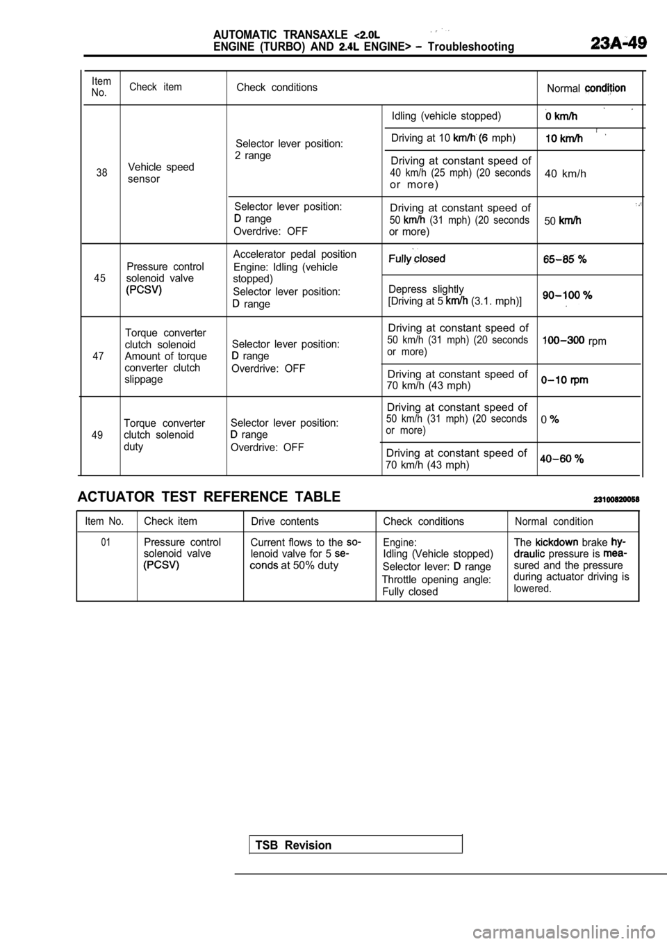
Item
No. Check itemCheck conditions
Normal
Idling (vehicle stopped)
Driving at 10 mph)Selector lever position:
2 range
Vehicle speedDriving at constant speed of
38 40 km/h (25 mph) (20 seconds40 km/hsensoro r m o r e )
Selector lever position:Driving at constant speed of range50 (31 mph) (20 seconds50Overdrive: OFF
or more)
Accelerator pedal position
Pressure control Engine: Idling (vehicle
45solenoid valvestopped)
Selector lever position: Depress slightly
range[Driving at 5 (3.1. mph)]
47
49
Torque converter
clutch solenoid
Amount of torque
converter clutch
slippage
Torque converter
clutch solenoid
duty Selector lever position:
range
Overdrive: OFF
Selector lever position:
range
Overdrive: OFF
Driving at constant speed of
50 km/h (31 mph) (20 seconds rpmor more)
Driving at constant speed of
70 km/h (43 mph)
Driving at constant speed of
50 km/h (31 mph) (20 seconds0or more)
Driving at constant speed of
70 km/h (43 mph)0
ACTUATOR TEST REFERENCE TABLE
Item No.Check item Drive contents
01Pressure controlCurrent flows to the
solenoid valve lenoid valve for 5
at 50% duty
Check conditions
Engine:
Idling (Vehicle stopped)
Selector lever:
range
Throttle opening angle: Fully closed
Normal condition
The brake
pressure is
sured and the pressure
during actuator driving is
lowered.
TSB Revision
Page 1060 of 2103
AUTOMATIC TRANSAXLE
ENGINE (TURBO) AND ENGINE> Troubleshooting
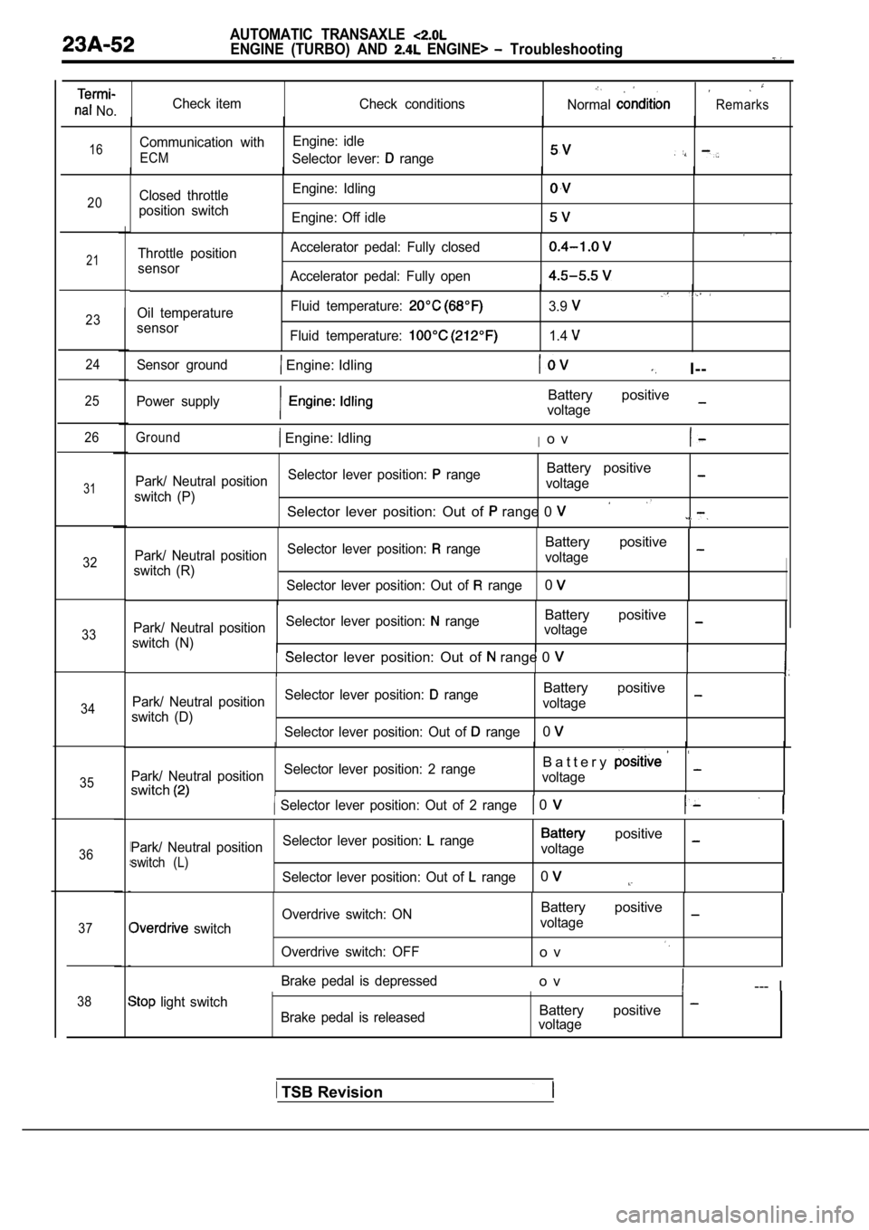
No.Check item
Check conditionsNormalRemarks
16Communication withEngine: idle
ECMSelector lever: range
20Closed throttle
position switch Engine: Idling
Engine: Off idle
21
23
24
25
26
31
32
33
34
35
36
37
38
Throttle position
sensor Accelerator pedal: Fully closed
Accelerator pedal: Fully open
Oil temperature
sensor Fluid temperature:
Fluid temperature:
3.9
1.4
Sensor ground Engine: IdlingI--
Power supplyBattery positive
voltage
Ground Engine: IdlingIo v
Park/ Neutral position
Selector lever position: rangeBattery positive
switch (P) voltage
Selector lever position: Out of range 0
Park/ Neutral position
Selector lever position: rangeBattery positive
switch (R) voltage
Selector lever position: Out of
range0
Park/ Neutral position Selector lever position: rangeBattery positive
switch (N) voltageSelector lever position: Out of range 0
Park/ Neutral position
Selector lever position: rangeBattery positive
switch (D) voltage
Selector lever position: Out of
range0
Park/ Neutral position Selector lever position: 2 rangeB a t t e r y
switchvoltage
Selector lever position: Out of 2 range 0
Park/ Neutral position
Selector lever position: range positive
switch (L)voltage
Selector lever position: Out of
range0
switch Overdrive switch: ON
Overdrive switch: OFF
Battery positive
voltage
o v
Brake pedal is depressedo v--- I
light switch Brake pedal is releasedBattery positive voltage
TSB Revision
Page 1130 of 2103

AUTOMATIC TRANSAXLE
ENGINE (NON-TURBO)> Troubleshooting
dure
4Conditions
Selector lever
position:
lever
Operation
Engine
(1) Driving in
gea
with selector
in range
( 2 ) D r i v i n g i n
gear with lever in 2 range
(3) Driving in gea
with selector
in range
(OverdriveOFF)
(4) Driving in
gear with selec-
tor lever in
range(Overdriveswitch ON) (for at least 1
minute)
Driving in Re-
verse gear with
selector lever in
range (for at
least 30 se-
conds)
1) Driving in gear, then apply
the brake until a
downshift
occurs. (Do this
at least 3 times)
ingine
1) Driving atconstant speedof 80 km/h (50
mph) with selec-
tor lever in
range(Overdriveswitch ON)
Judgment value
Data list
and
(1) Check the UD
and clutch
(2)
the 2-4
(3)
the OD
clutch: 35 to 85
2-4 clutch: 20 to 77
OD clutch: 75 to
UD clutch: 24 to 70
Data list and
InputEngine
OutputInput
gear ratio
Data list
Data list
1) Locked gear
Inspection item
A T F l e v e l
UD hydraulic
circuit
2-4 and
clutch
Gear ratio in
gear
I n p u t a n d
speed sensor
Solenoidswitch
valve (latched in the
LU position)
Lockup control
Solenoid
switch
(latched in the
position)
Diagnostic
trouble
code
35
46
TSB Revision
36
36
56
57
58
37
38
47
Page 1156 of 2103
AUTOMATIC TRANSAXLE
ENGINE (NON-TURBO)> Troubleshooting
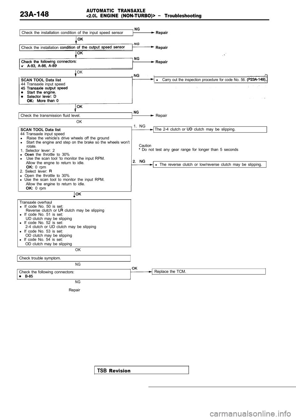
NGCheck the installation condition of the input speed sensor Repair
OK
NGCheck the installation Repair
NG Repair
l
OK
SCAN TOOL Data list lCarry out the inspection procedure for code No. 56.
44 Transaxle input speed
Check the transmission fluid level.
OK
SCAN TOOL Data list
44 Transaxle input speed l Raise the vehicle’s drive wheels off the ground
NG Repair
1. NG
The 2-4 clutch or clutch may be slipping.
l Start the engine and step on the brake so the wheel s won’t
rotate.1. Selector lever: 2
l the throttle to 30%
Caution Do not test any gear range for longer than 5 secon ds
l Use the scan tool ‘to monitor the input RPM.
Allow the engne to return to idle. OK: 0 rpm l
The reverse clutch or low/reverse clutch may be sli pping.
2. Select lever:
l Open the throttle to 30%
l Use the scan tool to monitor the input RPM.
Allow the enaine to return to idle.
OK: 0 rpm
Transaxle overhaul
l If code No. 50 is set:
Reverse clutch or
clutch may be slipping
l If code No. 51 is set:
UD clutch may be slipping
l If code No. 52 is set:
2-4 clutch or UD clutch may be slipping
l If code No. 53 is set:
OD clutch may be slipping
l If code No. 54 is set:
OD clutch may be slipping
OK
Check trouble symptom.
NG
Check the following connectors: Replace the TCM.
N G
TSBRevision
Repair
Page 1174 of 2103
AUTOMATIC TRANSAXLE
ENGINE (NON-TURBO)> On-vehicle Service
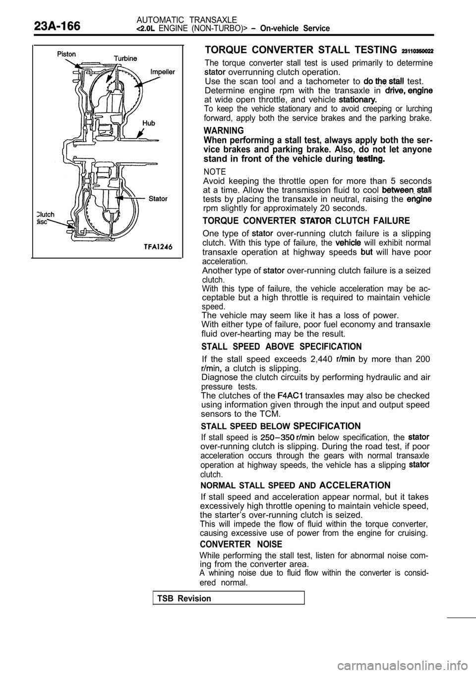
TORQUE CONVERTER STALL TESTING
The torque converter stall test is used primarily to determine
overrunning clutch operation.
Use the scan tool and a tachometer to
test.
Determine engine rpm with the transaxle in
at wide open throttle, and vehicle
To keep the vehicle stationary and to avoid creepin g or lurching
forward, apply both the service brakes and the parking brake.
WARNING
When performing a stall test, always apply both the ser-
vice brakes and parking brake. Also, do not let any one
stand in front of the vehicle during
NOTE
Avoid keeping the throttle open for more than 5 seconds
at a time. Allow the transmission fluid to cool
tests by placing the transaxle in neutral, raising the
rpm slightly for approximately 20 seconds.
TORQUE CONVERTER CLUTCH FAILURE
One type of over-running clutch failure is a slipping
clutch. With this type of failure, the will exhibit normal
transaxle operation at highway speeds will have poor
acceleration.
Another type of over-running clutch failure is a seized
clutch.
With this type of failure, the vehicle acceleration may be ac-
ceptable but a high throttle is required to maintai n vehicle
speed.
The vehicle may seem like it has a loss of power.
With either type of failure, poor fuel economy and transaxle
fluid over-hearting may be the result.
STALL SPEED ABOVE SPECIFICATION
If the stall speed exceeds 2,440 by more than 200
a clutch is slipping.
Diagnose the clutch circuits by performing hydrauli c and air
pressure tests.
The clutches of the transaxles may also be checked
using information given through the input and outpu t speed
sensors to the TCM.
STALL SPEED BELOW SPECIFICATION
If stall speed is below specification, the
over-running clutch is slipping. During the road te st, if poor
acceleration occurs through the gears with normal t ransaxle
operation at highway speeds, the vehicle has a slip ping
clutch.
NORMAL STALL SPEED AND ACCELERATION
If stall speed and acceleration appear normal, but it takes
excessively high throttle opening to maintain vehic le speed,
the starter’s over-running clutch is seized.
This will impede the flow of fluid within the torqu e converter,
causing excessive use of power from the engine for cruising.
CONVERTER NOISE
While performing the stall test, listen for abnormal noise com-
ing from the converter area.
A whining noise due to fluid flow within the conver ter is consid-
ered normal.
TSB Revision
Page 1510 of 2103
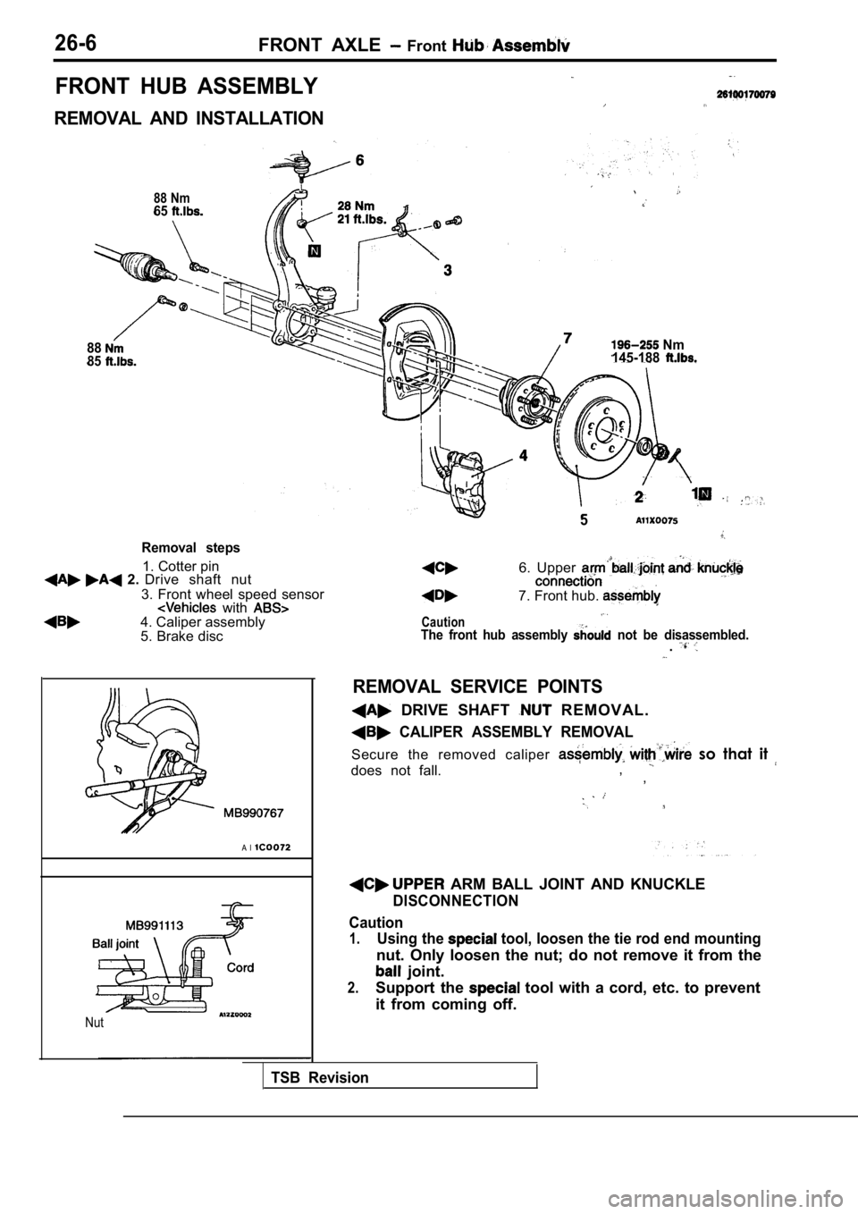
26-6FRONT AXLE Front
FRONT HUB ASSEMBLY
REMOVAL AND INSTALLATION
88 Nm65
8885
Removal steps
1. Cotter pin 2. Drive shaft nut
3. Front wheel speed sensor
with 4. Caliper assembly
5. Brake disc
A l
Nut
Nm
145-188
5
Caution
6. Upper
7. Front hub.
The front hub assembly not be disassembled..
REMOVAL SERVICE POINTS
DRIVE SHAFT R E M O V A L .
CALIPER ASSEMBLY REMOVAL
Secure the removed caliper so that it
does not fall., ,
ARM BALL JOINT AND KNUCKLE
DISCONNECTION
Caution
1.Using the tool, loosen the tie rod end mounting
nut. Only loosen the nut; do not remove it from the
joint.
2.Support the tool with a cord, etc. to prevent
it from coming off.
TSB Revision
Page 1539 of 2103
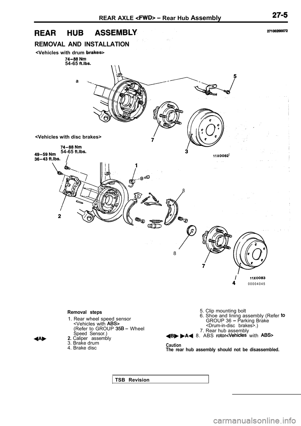
REAR AXLE Rear Hub Assembly
REMOVAL AND INSTALLATION
a
54-65
8
8
0 0 0 0 4 0 4 5
Removal steps
1. Rear wheel speed sensor
4. Brake disc 5. Clip mounting bolt
6. Shoe and lining assembly (Refer
GROUP 36 Parking Brake
7. Rear hub assembly 8. ABS with
CautionThe rear hub assembly should not be disassembled.
TSB Revision