Page 1118 of 2103

AUTOMATIC TRANSAXLE
ENGINE (TURBO) AND ENGINE> Transaxle Assembly
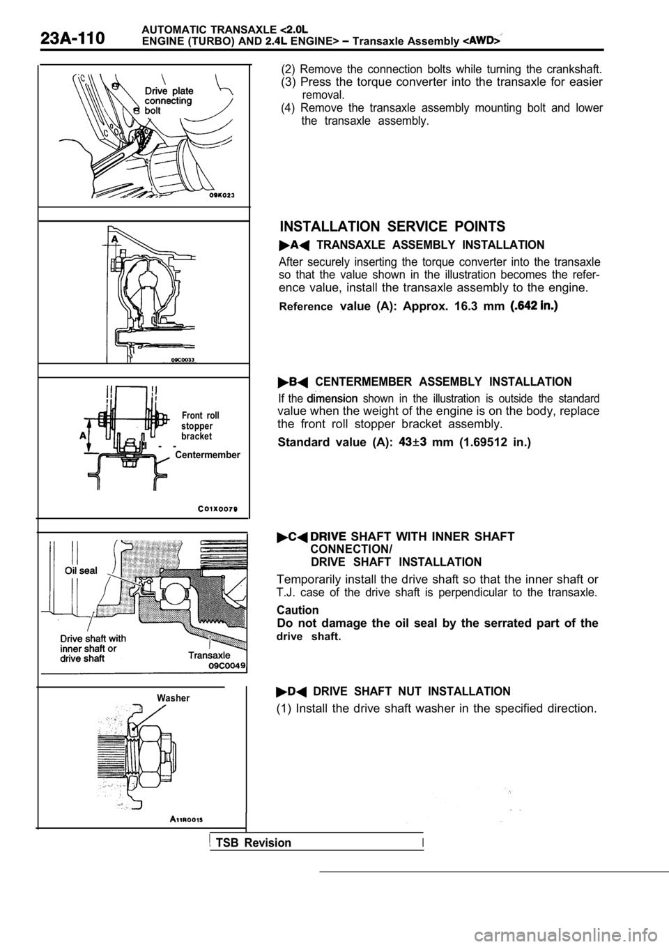
Front roll
I - -
stopper
bracket
Centermember
Washer
(2) Remove the connection bolts while turning the crankshaft.
(3) Press the torque converter into the transaxle for easier
removal.
(4) Remove the transaxle assembly mounting bolt and lower
the transaxle assembly.
INSTALLATION SERVICE POINTS
TRANSAXLE ASSEMBLY INSTALLATION
After securely inserting the torque converter into the transaxle
so that the value shown in the illustration becomes the refer-
ence value, install the transaxle assembly to the engine.
Reference value (A): Approx. 16.3 mm
CENTERMEMBER ASSEMBLY INSTALLATION
If the shown in the illustration is outside the standard
value when the weight of the engine is on the body, replace
the front roll stopper bracket assembly.
Standard value (A):
mm (1.69512 in.)
SHAFT WITH INNER SHAFT
CONNECTION/ DRIVE SHAFT INSTALLATION
Temporarily install the drive shaft so that the inn er shaft or
T.J. case of the drive shaft is perpendicular to th e transaxle.
Caution
Do not damage the oil seal by the serrated part of the
drive shaft.
DRIVE SHAFT NUT INSTALLATION
(1) Install the drive shaft washer in the specified direction.
TSB RevisionI
Page 1123 of 2103
AUTOMATIC TRANSAXLE.
ENGINE
GENERAL INFORMATION
The automatic transaxle comes in one model, namely,
22110010012
Items
ModelSpecifications
Applicable engine
Fully-adaptive, electronically controlled
full-automatic
Torque converter
Engine stall speed
with torque
Gear ratio 2 . 8 4 2I
1 . 5 7 3
‘ 1 . 0 0 0
Reverse
Final gear ratio
FUNCTION ELEMENT TABLE
. 0.689 ,
2.214
3 . 9 0 9
Shift Lever Position
PARK
REVERSE
NEUTRAL
StartPark Reverse Low/
Safety
drive
clutch clutchclutchclutch Reverse
clutch
Vehicle upshift and downshift speeds are increased when in these selector positions.
TSB Revision ,
Page 1124 of 2103
AUTOMATIC TRANSAXLE
ENGINE (NON-TURBO)? General
SECTIONAL VIEW
Case
Input speedOverdrive
clutch Reverse clutch
sensor
2-4 clutchUnderdrive
clutch
L o w / R e v e r s eclutch converter
Torqueconverter
.sensor
Oil pump
TSB Revision
shaft
gear
gear
Differential
Page 1149 of 2103

AUTOMATIC TRANSAXLE
ENGINE (NON-TURBO)> Troubleshooting
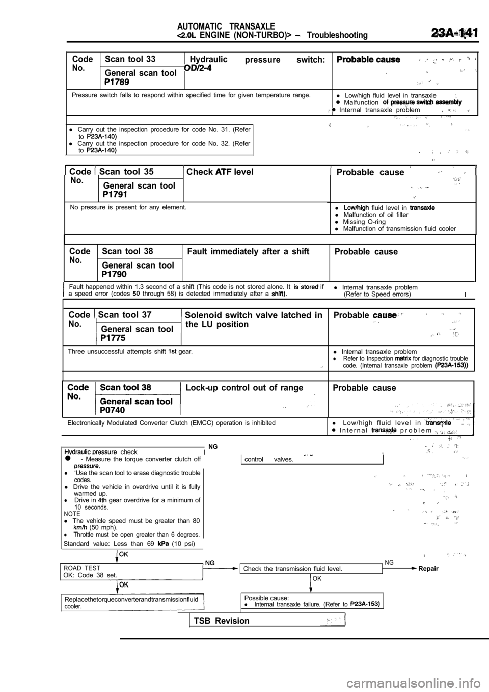
Code Scan tool 33Hydraulicpressureswitch:
No.General scan tool
Pressure switch falls to respond within specified t ime for given temperature range.
l Low/high fluid level in transaxle Malfunction Internal transaxle problem
,l Carry out the inspection procedure for code No. 31. (Refertol Carry out the inspection procedure for code No. 32. (Refer
to
Code Scan tool 35 Check level . Probable cause No.General scan tool
No pressure is present for any element.l fluid level in l
Malfunction of oil filter
l Missing O-ring
l Malfunction of transmission fluid cooler
Code Scan tool 38
Fault immediately after a shift Probable cause
No.General scan tool
Fault happened within 1.3 second of a shift (This code is not stored alone. It if
a speed error (codes through 58) is detected immediately after a l Internal transaxle problem
(Refer to Speed errors) I
Code
Scan tool 37 Solenoid switch valve latched in
No.General scan tool the LU position
Three unsuccessful attempts shift gear.
Probable
l
Internal transaxle problemlRefer to Inspection for diagnostic trouble
code. (Internal transaxle problem
Lock-up control out of rangeProbable cause
Electronically Modulated Converter Clutch (EMCC) op eration is inhibitedl L o w / h i g h f l u i d l e v e l i n I n t e r n a l p r o b l e m
checkNGI -..< .
l - Measure the torque converter clutch offcontrol valves.
l‘Use the scan tool to erase diagnostic troublecodes.l Drive the vehicle in overdrive until it is fully
warmed up.
lDrive in gear overdrive for a minimum of10 seconds.NOTEl The vehicle speed must be greater than 80 (50 mph).lThrottle must be open greater than 6 degrees.
Standard value: Less than 69 (10 psi)
ROAD TESTOK: Code 38 set. Check the transmission fluid level.OK
NG Repair
Replacethetorqueconverterandtransmissionfluid
cooler.
Possible cause:lInternal transaxle failure. (Refer to
TSB Revision
Page 1154 of 2103

AUTOMATIC TRANSAXLE
ENGINE (NON-TURBO)> Troubleshooting
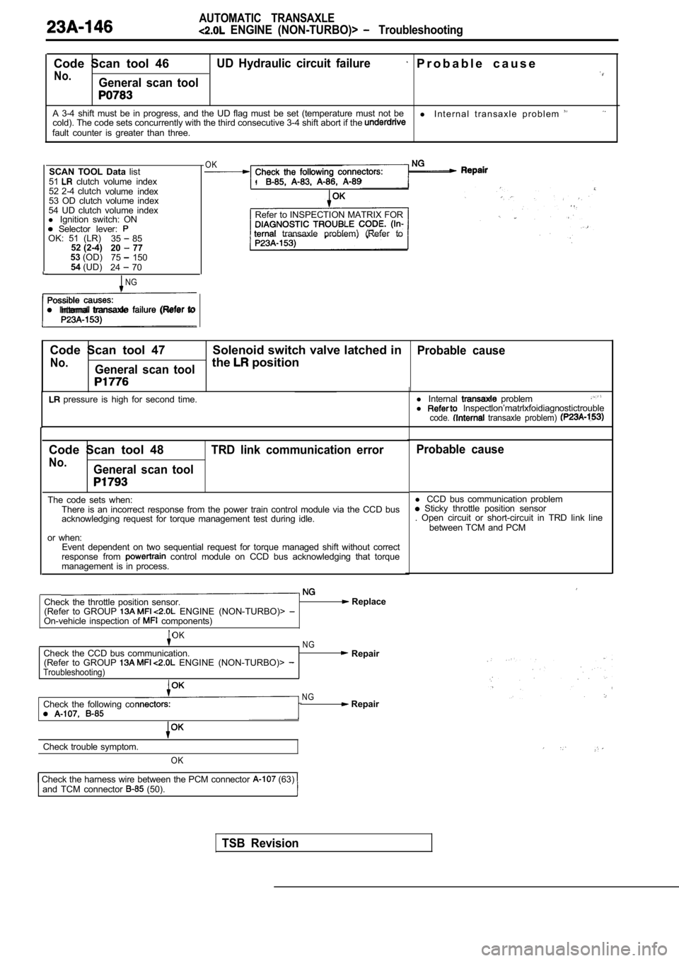
Code Scan tool 46UD Hydraulic circuit failure P r o b a b l e c a u s e
No.General scan tool
A 3-4 shift must be in progress, and the UD flag must be set (temperature must not be
l I n t e r n a l t r a n s a x l e p r o b l e m cold). The code sets concurrently with the third co nsecutive 3-4 shift abort if the fault counter is greater than three.
SCAN TOOL Data list
51
clutch volume index
52 2-4 clutch volume index
53 OD clutch volume index
54 UD clutch volume index
l Ignition switch: ON
Selector lever: OK: 51 (LR)
35 85
52 (2-4) 20 77
53 (OD)
75 150
54 (UD)
24 70
NG
l Internal transaxle (Refer to
OK
.
Refer to INSPECTION MATRIX FOR
transaxle problem) (Refer to
Code Scan tool 47 Solenoid switch valve latched in
Probable cause
No.General scan toolthe position
pressure is high for second time. l
Internal probleml lnspectlon’matrlxfoidiagnostictroublecode. transaxle problem)
Code Scan tool 48
No.General scan tool TRD link communication error
The code sets when:
There is an incorrect response from the power train control module via the CCD bus
acknowledging request for torque management test du ring idle.
or when: Event dependent on two sequential request for torqu e managed shift without correct
response from
control module on CCD bus acknowledging that torqu e
management is in process.
Check the throttle position sensor.
(Refer to GROUP ENGINE (NON-TURBO)> On-vehicle inspection of components)
Replace
OKNGCheck the CCD bus communication. Repair
(Refer to GROUP ENGINE (NON-TURBO)> Troubleshooting)
Check the following coNG Repair
Check trouble symptom.
OK
Check the harness wire between the PCM connector (63) and TCM connector (50).
Probable cause
l CCD bus communication problem Sticky throttle position sensor
. Open circuit or short-circuit in TRD link line
between TCM and PCM
TSB Revision
Page 1162 of 2103
AUTOMATIC TRANSAXLE
ENGINE Troubleshooting
PROBABLE CAUSE
No.Probable cause
1Low fluid level
2Aerated fluid (High fluid level)
3Worn or damaged reaction shaft support sealing
4worn or damaged input shaft sealing
5Worn pump
6
Damaged or failed underdrive clutch
7Damaged or failed ovedrive clutch
8Damaged or failed reverse clutch
9Damaged or failed 2-4 clutch
10Damaged or failed low/reverse clutch
11Damaged clutch seal
12Worn or damaged accumulator sealing
13Plugged filter
14Stuck/sticky valves
15Solenoid switch valve
16Lock-up switch valve
17Torque converter control valve
18Regulator valve
19Valve body leakage
20Pressures too high
21Internal solenoid leak
22Torque converter clutch failure
23Faulty cooling system
24Damaged speed sensor gear teeth
25Planetary gear sets broken or seized
.
,
TSB Revision
Page 1164 of 2103
AUTOMATIC TRANSAXLE
ENGINE (NON-TURBO)> Troubleshooting
Trouble symptom
torque converter control shift
PROBABLE CAUSE
No.Probable cause
18Drive shaft(s) bushing(s) worn or damaged
19Worn or broken reaction shaft support sealing
20Worn or damaged input shaft sealing
21Valve body malfunction or leakage
22Hydraulic pressure too low
23Hydraulic pressure too high
24 Faulty oil pump
25Oil filter clogged
26Low fluid level
27 High fluid level
28Aerated fluid
29 Engine idle too low
30Engine idle too high
31Normal solenoid operation
32Solenoid sound cover loose
33Sticking lockup piston
34 Torque converter failure
TSB Revision
Page 1174 of 2103

AUTOMATIC TRANSAXLE
ENGINE (NON-TURBO)> On-vehicle Service
TORQUE CONVERTER STALL TESTING
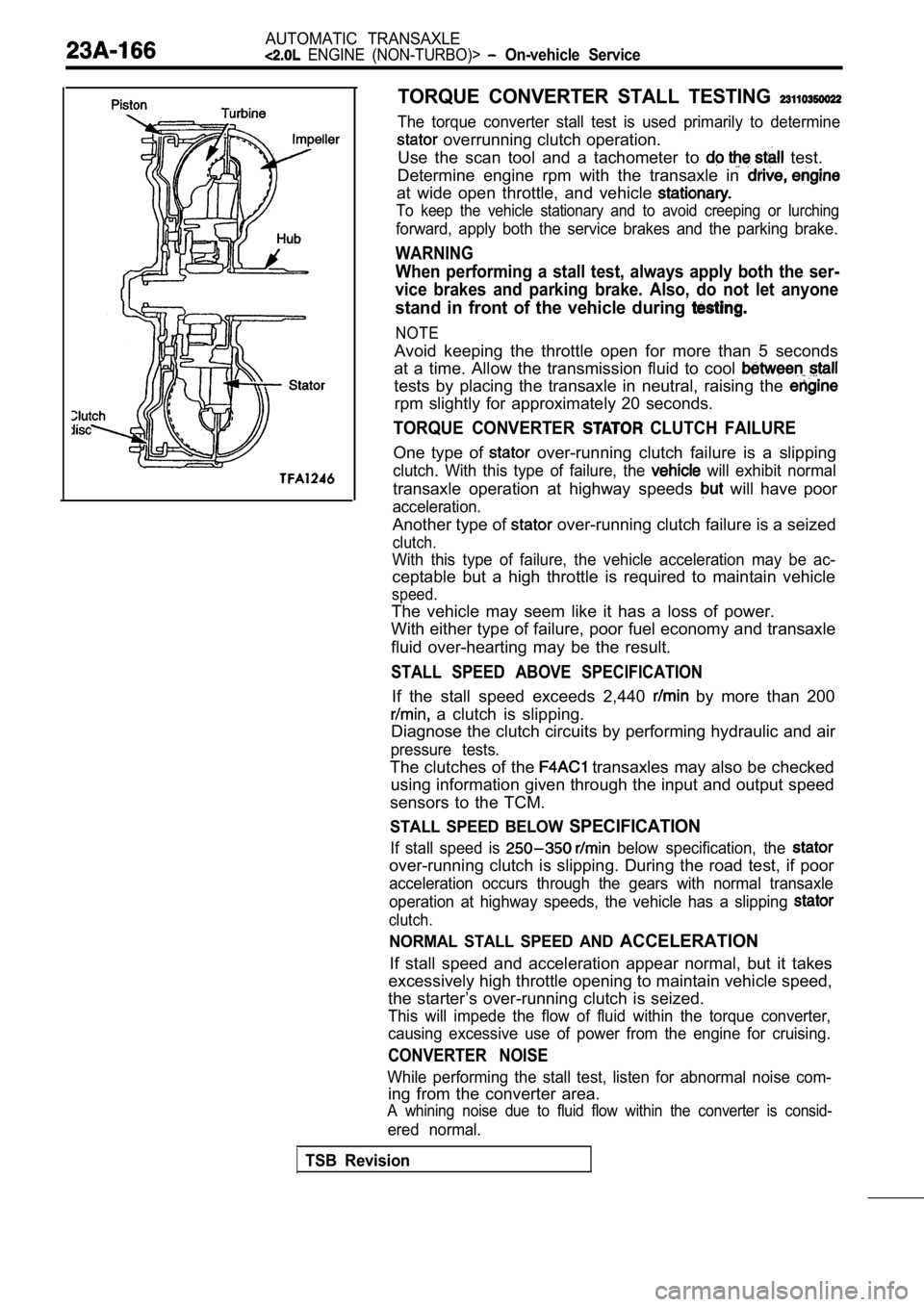
The torque converter stall test is used primarily to determine
overrunning clutch operation.
Use the scan tool and a tachometer to
test.
Determine engine rpm with the transaxle in
at wide open throttle, and vehicle
To keep the vehicle stationary and to avoid creepin g or lurching
forward, apply both the service brakes and the parking brake.
WARNING
When performing a stall test, always apply both the ser-
vice brakes and parking brake. Also, do not let any one
stand in front of the vehicle during
NOTE
Avoid keeping the throttle open for more than 5 seconds
at a time. Allow the transmission fluid to cool
tests by placing the transaxle in neutral, raising the
rpm slightly for approximately 20 seconds.
TORQUE CONVERTER CLUTCH FAILURE
One type of over-running clutch failure is a slipping
clutch. With this type of failure, the will exhibit normal
transaxle operation at highway speeds will have poor
acceleration.
Another type of over-running clutch failure is a seized
clutch.
With this type of failure, the vehicle acceleration may be ac-
ceptable but a high throttle is required to maintai n vehicle
speed.
The vehicle may seem like it has a loss of power.
With either type of failure, poor fuel economy and transaxle
fluid over-hearting may be the result.
STALL SPEED ABOVE SPECIFICATION
If the stall speed exceeds 2,440 by more than 200
a clutch is slipping.
Diagnose the clutch circuits by performing hydrauli c and air
pressure tests.
The clutches of the transaxles may also be checked
using information given through the input and outpu t speed
sensors to the TCM.
STALL SPEED BELOW SPECIFICATION
If stall speed is below specification, the
over-running clutch is slipping. During the road te st, if poor
acceleration occurs through the gears with normal t ransaxle
operation at highway speeds, the vehicle has a slip ping
clutch.
NORMAL STALL SPEED AND ACCELERATION
If stall speed and acceleration appear normal, but it takes
excessively high throttle opening to maintain vehic le speed,
the starter’s over-running clutch is seized.
This will impede the flow of fluid within the torqu e converter,
causing excessive use of power from the engine for cruising.
CONVERTER NOISE
While performing the stall test, listen for abnormal noise com-
ing from the converter area.
A whining noise due to fluid flow within the conver ter is consid-
ered normal.
TSB Revision