1990 MITSUBISHI SPYDER torque
[x] Cancel search: torquePage 1044 of 2103
![MITSUBISHI SPYDER 1990 Service Repair Manual AUTOMATIC TRANSAXLE
ENGINE (TURBO) AND ENGINE> ,
INSPECTION PROCEDURE 5 .
lDoes not move (forward or reverse)
[Comment]
P r o b a b l e c a u s e ‘
When the engine is idling, the ve MITSUBISHI SPYDER 1990 Service Repair Manual AUTOMATIC TRANSAXLE
ENGINE (TURBO) AND ENGINE> ,
INSPECTION PROCEDURE 5 .
lDoes not move (forward or reverse)
[Comment]
P r o b a b l e c a u s e ‘
When the engine is idling, the ve](/manual-img/19/57345/w960_57345-1043.png)
AUTOMATIC TRANSAXLE
ENGINE (TURBO) AND ENGINE> ,
INSPECTION PROCEDURE 5 .
lDoes not move (forward or reverse)
[Comment]
P r o b a b l e c a u s e ‘
When the engine is idling, the vehicle does not mov e forward or in reverse even if the selectorl
Abnormal reducing pressure
l
lever is shifted from
to 2, or range. In such cases, the cause is probably abnorm alMalfunction of power train
l
reducing pressure, or a defective oil pump or power train.Malfunction of oil pump
l ‘ o f v a l v e b o d y
Refer to Automatic Transaxle Overhaul
O K
Hydraulic pressure test (Refer to .
l Measure the reducing pressure in range while the
engine is idling.
Standard value:
psi)
NG
Reducing pressure OK
Power train check lDisassemble the transaxle, check the condition of t he
and repair or replace if necessary.
Check to be sure that there are no abnormalities su ch
lIf it is considered that the damage or chipping can
not
be repaired, replace the valve body assembly.If there is an abnormality, replace the oil pump as sembly.
INSPECTION PROCEDURE 6
l Engine stalling during shifting
cause
[Comment] Malfunction of engine systemWhen the engine is idling, the engine stalls when t he selector lever is shifted from to l
2, or range. In such cases, the cause is probably a defe ctive engine system or damper lMalfunction of torque solenoid
clutch control solenoid valve. Malfunction of body l
Malfunction of torque converter
Refer to Automatic Transaxle Overhaul
Enaine check .
l the control system, ignition system, fuel system a nd main engine system, and confirm that everything is l If there is an abnormality, repair or replace the e ngine system.
After completion
Solenoid valve connector check
l Check to be sure that there is no water in the conn ector.
l Check to be sure that none of the terminals are sho
rted to each other.
After completion
Torque converter clutch solenoid check l Check to be sure that the valve is not sticking due to foreign materials packed inside solenoid.
l If there is an abnormality, replace the solenoid as sembly.
After completion
Transaxle cooling system check l Check for plugged cooler lines.
l Check for plugged oil cooler.
After completion
Valve body disassembly, cleaning and reassembly
l
l Pay particular attention to loosening of bolts, and
to damage, chipping or slippage of O-rings, valve intermediate plate and body.
If it is considered that the damage or chipping can not be repaired, replace the valve body assembly.
After completion
Torque converter check l Check to be sure that there is no sticking due to s eparation from the damper clutch.
l If there is an abnormality, replace the torque conv erter assembly.
Revision
Page 1051 of 2103
![MITSUBISHI SPYDER 1990 Service Repair Manual AUTOMATIC TRANSAXLE
ENGINE (TURBO) AND ENGINE,
INSPECTION PROCEDURE 14
Poor accelerationI
[Comment]l Malfunction of clutches and brakesWhile driving, acceleration is poor even if MITSUBISHI SPYDER 1990 Service Repair Manual AUTOMATIC TRANSAXLE
ENGINE (TURBO) AND ENGINE,
INSPECTION PROCEDURE 14
Poor accelerationI
[Comment]l Malfunction of clutches and brakesWhile driving, acceleration is poor even if](/manual-img/19/57345/w960_57345-1050.png)
AUTOMATIC TRANSAXLE
ENGINE (TURBO) AND ENGINE,
INSPECTION PROCEDURE 14
Poor accelerationI
[Comment]l Malfunction of clutches and brakesWhile driving, acceleration is poor even if downshi fting is performed. In such cases, the causeMalfunction of engine system
is probably a defective clutch or brake, or a defec tive engine system.
Refer to Automatic Transaxle Overhaul
Engine system check
lCheck the control system, ignition system, fuel sys temand main engine system, and confirm that everything
is normal.
lIf there is an abnormality, repair or replace the enginesystem.
After completion
Clutch and brake check
lCheck each end play, and if they exceed the standar d
l Check for burning and wear in each facing.
INSPECTION PROCEDURE 15 ,
l VibrationProbable cause
[Comment] l Abnormal torque converter pressure
Vibration occurs when driving at constant speed or when accelerating in top range. In such l
Malfunction of engine system
cases, the cause is probably abnormal torque conver ter clutch pressure or a defective torque
Malfunction of torque converter converter. o f v a l v e b o d y
Refer to Automatic
sensor connector is disconnected?
No
Yes
Standard value: (64-92 psi)
OK
If it is considered that the damage or chipping can not
be repaired, replace the valve body assembly.
TSB Revision
Page 1057 of 2103
AUTOMATIC TRANSAXLE
ENGINE (TURBO) AND ENGINE> Troubleshooting
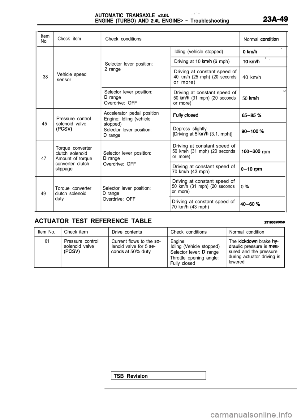
Item
No. Check itemCheck conditions
Normal
Idling (vehicle stopped)
Driving at 10 mph)Selector lever position:
2 range
Vehicle speedDriving at constant speed of
38 40 km/h (25 mph) (20 seconds40 km/hsensoro r m o r e )
Selector lever position:Driving at constant speed of range50 (31 mph) (20 seconds50Overdrive: OFF
or more)
Accelerator pedal position
Pressure control Engine: Idling (vehicle
45solenoid valvestopped)
Selector lever position: Depress slightly
range[Driving at 5 (3.1. mph)]
47
49
Torque converter
clutch solenoid
Amount of torque
converter clutch
slippage
Torque converter
clutch solenoid
duty Selector lever position:
range
Overdrive: OFF
Selector lever position:
range
Overdrive: OFF
Driving at constant speed of
50 km/h (31 mph) (20 seconds rpmor more)
Driving at constant speed of
70 km/h (43 mph)
Driving at constant speed of
50 km/h (31 mph) (20 seconds0or more)
Driving at constant speed of
70 km/h (43 mph)0
ACTUATOR TEST REFERENCE TABLE
Item No.Check item Drive contents
01Pressure controlCurrent flows to the
solenoid valve lenoid valve for 5
at 50% duty
Check conditions
Engine:
Idling (Vehicle stopped)
Selector lever:
range
Throttle opening angle: Fully closed
Normal condition
The brake
pressure is
sured and the pressure
during actuator driving is
lowered.
TSB Revision
Page 1059 of 2103
AUTOMATIC TRANSAXLE
ENGINE (TURBO) AND ENGINE> Troubleshooting
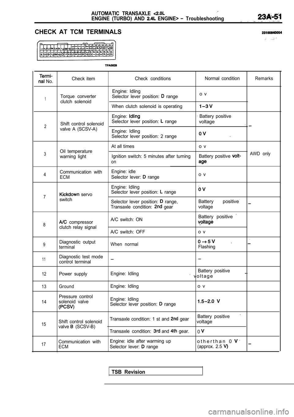
CHECK AT TCM TERMINALS
No.Check item
Check conditions Normal conditionRemarks
Engine: Idling
Torque converter Selector lever position:
rangeo v
1clutch solenoid
When clutch solenoid is operating
Engine: Battery positive
Shift control solenoid Selector lever position:
range
2voltage
valve A (SCSV-A)
Engine: Idling
Selector lever position: 2 range
At all timeso v
3Oil temperature
warning light Ignition switch: 5 minutes after turning
Battery positive AWD only
on
Communication with Engine: idle4Selector lever: rangeo vECM
Engine: Idling
Selector lever position:
range7 servo
switch Selector lever position:
range,Battery positive
Transaxle condition: gearvoltage
Battery positive
8 compressor A/C switch: ON
clutch relay signal
A/C switch: OFFo v
9Diagnostic outputWhen normal .
terminalFlashing
11Diagnostic test mode
control terminal
12Power supply Engine: Idling Battery positive v o l t a g e
13
14
15
17
GroundEngine: Idlingo v
Pressure control
solenoid valve Engine: Idling
Selector lever position:
range
Battery positive
Shift control solenoid Transaxle condition: 1 st and gearvoltage
valve (SCSV-B)
Transaxle condition: and gear.0
Communication with Engine: idle after warming upo t h e r t h a n 0
ECMSelector lever: range
(approx. 2.5
TSB Revision
Page 1065 of 2103
AUTOMATIC TRANSAXLE
ENGINE (TURBO) AND On-vehicle
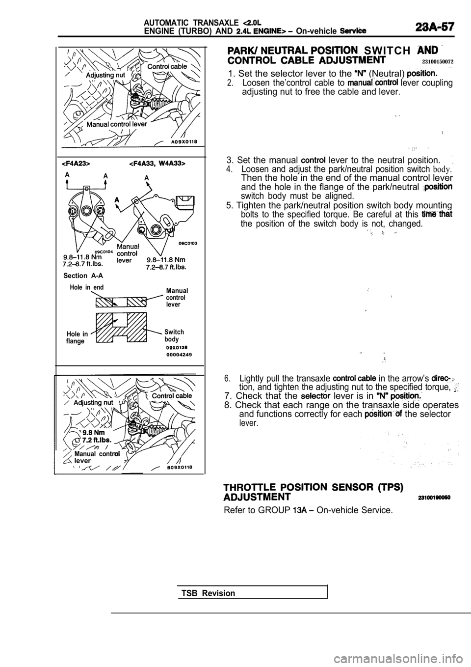
AA
A
Section A-A
Hole in endManualcontrol
lever
Hole in
flangeSwitch
body
00004249
Manual control lever
S W I T C H
23100150072
1. Set the selector lever to the (Neutral)
2.Loosen the’control cable to lever coupling
adjusting nut to free the cable and lever.
3. Set the manual lever to the neutral position.
4.Loosen and adjust the park/neutral position switch body.
Then the hole in the end of the manual control leve r
and the hole in the flange of the park/neutral
switch body must be aligned.
5. Tighten the park/neutral position switch body mo unting
bolts to the specified torque. Be careful at this
the position of the switch body is not, changed. ,
6.Lightly pull the transaxle in the arrow’s
tion, and tighten the adjusting nut to the specified torque,
7. Check that the lever is in
8. Check that each range on the transaxle side oper ates
and functions correctly for each the selector
lever.
Refer to GROUP On-vehicle Service.
TSB Revision
Page 1071 of 2103
AUTOMATIC TRANSAXLE
ENGINE (TURBO) AND ENGINE> On-vehicle Service
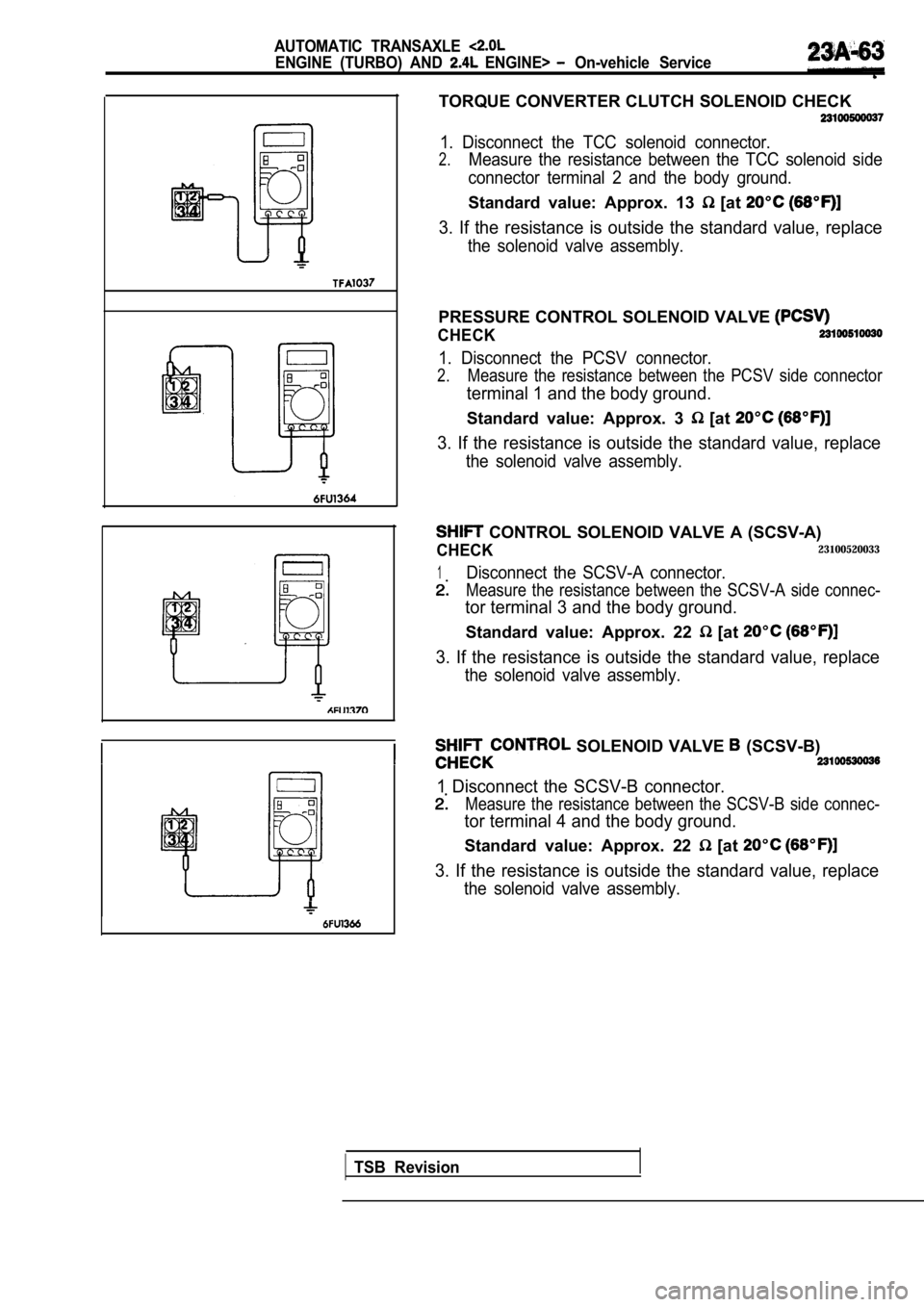
TORQUE CONVERTER CLUTCH SOLENOID CHECK
1. Disconnect the TCC solenoid connector.
2.Measure the resistance between the TCC solenoid side
connector terminal 2 and the body ground.
Standard value: Approx. 13 [at
3. If the resistance is outside the standard value, replace
the solenoid valve assembly.
PRESSURE CONTROL SOLENOID VALVE
CHECK
1. Disconnect the PCSV connector.
2.Measure the resistance between the PCSV side connec tor
terminal 1 and the body ground.
Standard value: Approx. 3 [at
3. If the resistance is outside the standard value, replace
the solenoid valve assembly.
CONTROL SOLENOID VALVE A (SCSV-A)
CHECK23100520033
1Disconnect the SCSV-A connector.
Measure the resistance between the SCSV-A side conn ec-
tor terminal 3 and the body ground.
Standard value: Approx. 22 [at
3. If the resistance is outside the standard value, replace
the solenoid valve assembly.
SOLENOID VALVE (SCSV-B)
1 Disconnect the SCSV-B connector.
Measure the resistance between the SCSV-B side conn ec-
tor terminal 4 and the body ground.
Standard value: Approx. 22 [at
3. If the resistance is outside the standard value, replace
the solenoid valve assembly.
TSB Revision
Page 1072 of 2103
AUTOMATIC TRANSAXLE
ENGINE (TURBO) AND On-vehicle Service
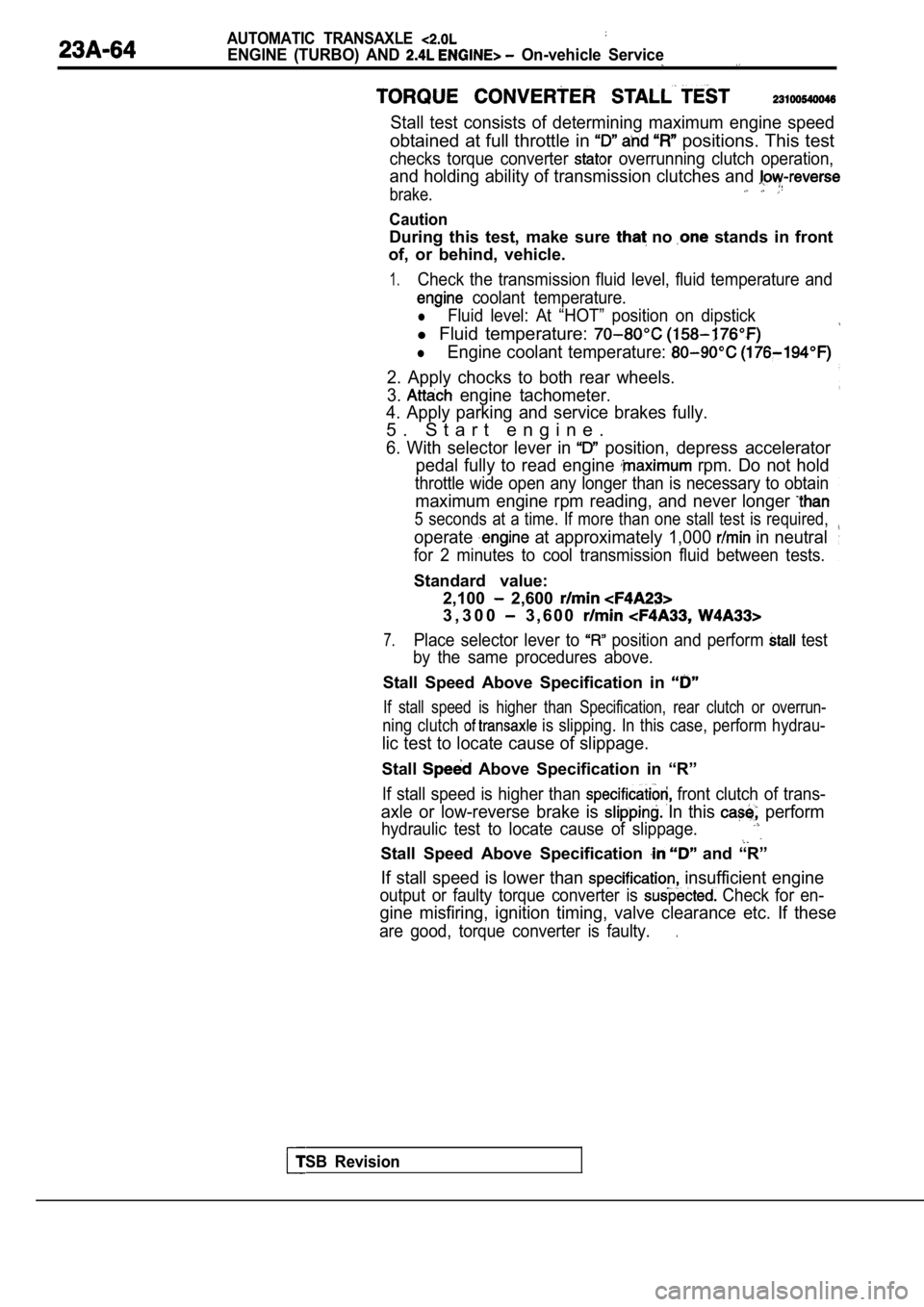
Stall test consists of determining maximum engine speed
obtained at full throttle in positions. This test
checks torque converter overrunning clutch operation,
and holding ability of transmission clutches and
brake.
Caution
During this test, make sure no stands in front
of, or behind, vehicle.
1.Check the transmission fluid level, fluid temperatu re and
coolant temperature.
lFluid level: At “HOT” position on dipstick
l Fluid temperature:
lEngine coolant temperature:
2. Apply chocks to both rear wheels.
3.
engine tachometer.
4. Apply parking and service brakes fully.
5 . S t a r t e n g i n e .
6. With selector lever in position, depress accelerator
pedal fully to read engine
rpm. Do not hold
throttle wide open any longer than is necessary to obtain
maximum engine rpm reading, and never longer
5 seconds at a time. If more than one stall test is required,
operate at approximately 1,000 in neutral
for 2 minutes to cool transmission fluid between te sts.
Standard value:
TSB Revision
2,100 2,600
3 , 3 0 0 3 , 6 0 0
7.Place selector lever to position and perform test
by the same procedures above.
Stall Speed Above Specification in
If stall speed is higher than Specification, rear c lutch or overrun-
ning clutch is slipping. In this case, perform hydrau-
lic test to locate cause of slippage.
Stall Above Specification in “R”
If stall speed is higher than front clutch of trans-
axle or low-reverse brake is In this perform
hydraulic test to locate cause of slippage.
Stall Speed Above Specification and “R”
If stall speed is lower than insufficient engine
output or faulty torque converter is Check for en-
gine misfiring, ignition timing, valve clearance etc. If these
are good, torque converter is faulty..
Page 1073 of 2103
AUTOMATIC TRANSAXLE
ENGINE (TURBO) AND ENGINE> On-vehicle
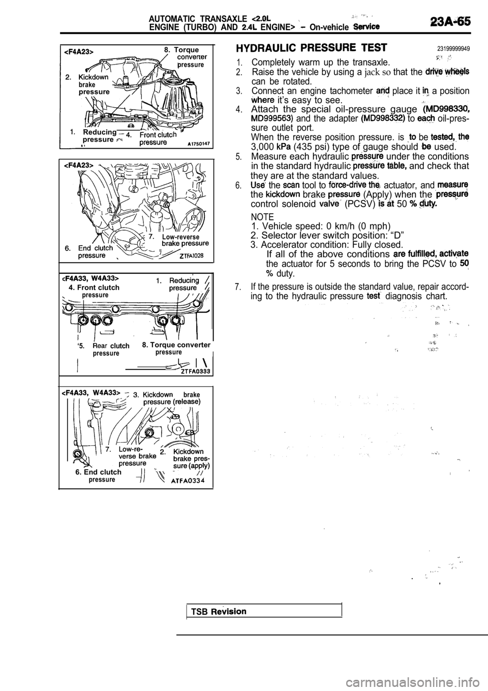
8. Torque
pressure
brakepressure
Reducingpressure
Low-reverse
4. Front clutchpressure
‘5. clutch8. Torque converter
pressurepressureI
brake
6. End clutch
23199999949
1.
2.
3.
4.
5.
6.
7.
Completely warm up the transaxle.
Raise the vehicle by using a jack so that the
can be rotated.
Connect an engine tachometer
place it a position
it’s easy to see.
Attach the special oil-pressure gauge
and the adapter to oil-pres-
sure outlet port.
When the reverse position pressure. is
be
3,000 (435 psi) type of gauge should used.
Measure each hydraulic
under the conditions
in the standard hydraulic
and check that
they are at the standard values.
the tool to actuator, and
the brake (Apply) when the
control solenoid (PCSV) 50
NOTE
1. Vehicle speed: 0 km/h (0 mph)
2. Selector lever switch position: “D”
3. Accelerator condition: Fully closed.
If all of the above conditions
the actuator for 5 seconds to bring the PCSV to
duty.
If the pressure is outside the standard value, repa ir accord-
ing to the hydraulic pressure diagnosis chart.
.
.
,
pressure
TSB