1990 MITSUBISHI SPYDER coolant temperature
[x] Cancel search: coolant temperaturePage 694 of 2103
E N G I N E C O O L I N G
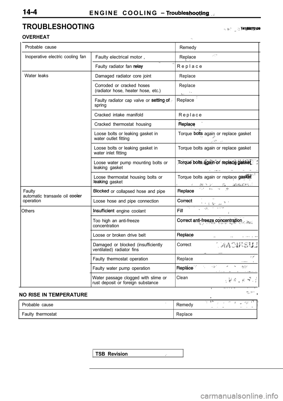
TROUBLESHOOTING
OVERHEAT
Probable cause
Inoperative electric cooling fan
Water leaks
Faulty electrical motor ,
Faulty radiator fan
Damaged radiator core joint
Corroded or cracked hoses
(radiator hose, heater hose, etc.)
Remedy
Replace
R e p l a c e
Replace
Replace
.
Faulty radiator cap valve or Replace
spring
Cracked intake manifold
Cracked thermostat housing
R e p l a c e
Loose bolts or leaking gasket in
water outlet fitting Torque again or replace gasket
Loose bolts or leaking gasket in
water inlet fitting Torque bolts again or replace gasket
Faulty Loose water pump mounting bolts or
leaking gasket
Loose thermostat housing bolts or
gasket
automatic transaxle oil
operation
Others
or collapsed hose and pipe
Loose hose and pipe connection
engine coolant
Too high an anti-freeze
concentration
Torque bolts again or replace . . .
.
Loose or broken drive belt
Damaged or blocked (insufficiently
ventilated) radiator fins
Faulty thermostat operation. .
Correct
Replace .
Faulty water pump operation .
Water passage clogged with slime orClean
rust deposit or foreign substance, . .
NO RISE IN TEMPERATURE
,
.
Probable cause
Faulty thermostatRemedy
Replace
TSB Revision
Page 721 of 2103
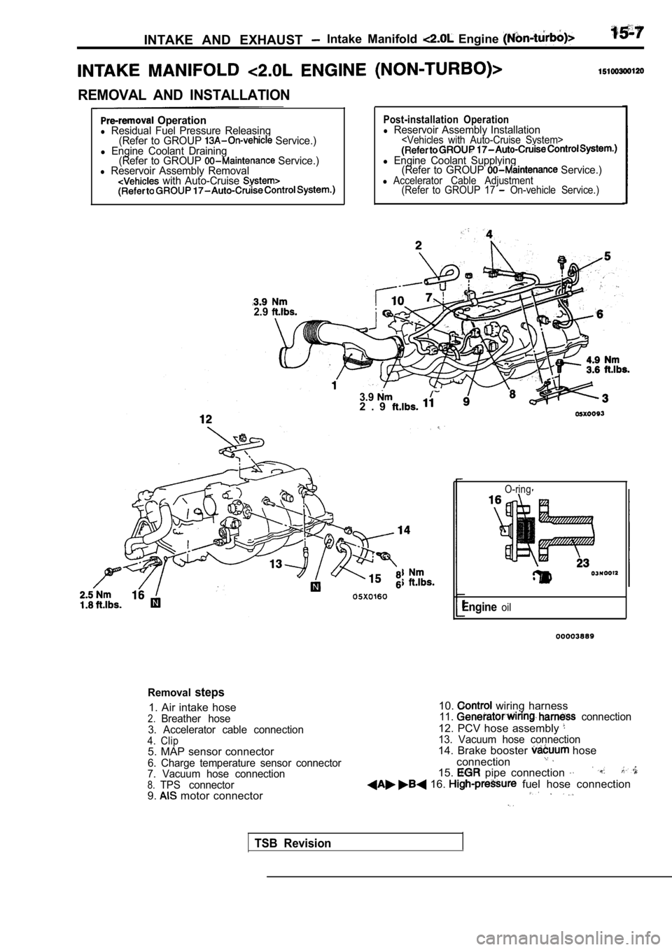
INTAKE AND EXHAUST Intake Manifold Engine
REMOVAL AND INSTALLATION
Operationl Residual Fuel Pressure Releasing(Refer to GROUP Service.)l Engine Coolant Draining(Refer to GROUP Service.)l Reservoir Assembly Removal with Auto-Cruise
2.9
Post-installation Operationl Reservoir Assembly Installation
l Engine Coolant Supplying (Refer to GROUP Service.)l Accelerator Cable Adjustment (Refer to GROUP 17 On-vehicle Service.)
3.92 . 9
O-ring
Engineoil
Removalsteps
1. Air intake hose2.Breather hose
3. Accelerator cable connection
4. Clip5. MAP sensor connector
6. Charge temperature sensor connector
7. Vacuum hose connection
8.TPS connector9. motor connector 10.
wiring harness11. connection
12. PCV hose assembly 13. Vacuum hose connection14. Brake booster hose
connection
15. pipe connection
16. fuel hose connection
TSB Revision
Page 725 of 2103
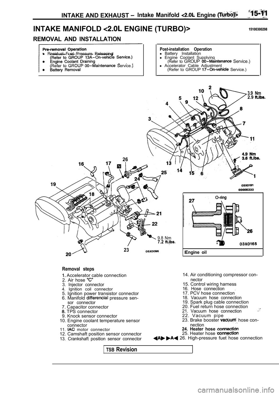
INTAKE AND EXHAUST Intake Manifold Engine
INTAKE MANIFOLD ENGINE (TURBO)>15100300298
REMOVAL AND INSTALLATION
l Residual Fuel Pressure Releasing
(Refer to GROUP
Service.)
26
Post-installation Operationl Battery Installation
l Engine Coolant Supplying
(Refer to GROUP Service.)l Accelerator Cable Adjustment
(Refer to GROUP Service.)
3.9 Nm2.9
9.8 Nm7.2
23
Removal steps
Accelerator cable connection
2. Air hose
3. Injector connector4. Ignition coil connector 5. Ignition power transistor connector
6. Manifold
pressure sen-sor connector
14. Air conditioning compressor con-
7. Capacitor connector
TPS connector
9. Knock sensor connector
10. Engine coolant temperature sensor
connector11. motor connector
12. Camshaft position sensor connector
13. Crankshaft position sensor connector nector
15. Control wiring harness16. Hose connection.17. PCV hose connection18. Vacuum hose connection19. Spark plug cable connection
20. Fuel return hose connection
21. Vacuum hose connection2 2 . V a c u u m p i p e
23. Brake booster hose con-
nection24. Heater hose 25. Heater hose 26. High-pressure fuet hose connection
IEngine oil
TSBRevision
Page 741 of 2103

CONTENTS
AUTO-CRUISE CONTROL SYSTEM
. . . . . . . . . . . . . . . . . . . . . . . . . . . . . . . . . . . . .7
AUTO-CRUISE CONTROL* . . . . . . . . . . . . . . 40
GENERAL INFORMATION . . . . . . . . . . . . . . . . 7
ON-VEHICLE SERVICE. . . . . . . . . . . . . . . . . 33
Auto-cruise Control Cable Check and
Adjustment . . . . . . . . . . . . . . . . . . . . . . . . . . . . . .
33
Auto-cruise Control Component Check . . . . . 37
Auto-cruise Control System Operation Check
. . . . . . . . . . . . . . . . . . . . . . . . . . . . . . . . . . . . . . . . .
35
SERVICE SPECIFICATIONS . . . . . . . . . . . . . 8
SPECIAL TOOLS . . . . . . . . . . . . . . . . . . . . . . . . 8
TROUBLESHOOTING
ENGINE (NON-TURBO)> . . . . . . . . . . . 9
TROUBLESHOOTING
(TURBO) AND ENGINE> . . . . .
EMISSION CONTROL’ SYSTEM
. . . . .
CATALYTIC . . . . . . . . . . . . . .
General Information . . . . . . . . . . . . . . . . . . 57
EVAPORATIVE EMISSION .
SYSTEM. . . . . . . . . . . . . . . .
Air Conditioning . . . . . . . . . . . . . . . . . . . 52
Component Location
. . . . . . . . . . . . . . . . . .
Engine Coolant Temperature Sensor
Intake Air Temperature Sensor . . . . . . . . . . . . 52
WARNINGS REGARDING SERVICING OF SUPPLEMENTAL RESTRA INT SYSTEM (SRS) EQUIPPED
WARNING!
(1) Improper serviceor maintenance of any component of the or any SRS-related can to injuryorcleathtoservicepersonnel (from inadvertentfiring the SRS inoperative).
(2) Service or maintenance of any SRS component or SRS-related component must be performed only
MITSUBISHI dealer.
(3) MITSUBISHI dealer personnel must thoroughly rev iew this manual, and especially its GROUP
Restraint System (SRS) and GROUP 00 Maintenance Service, before any service or maintenance of any
componentof the SRS or any SRS-related component.
NOTEJhe includes the following components: warning light, air bag module, clock components (that may have to be removed/installed in connection with or areIndicated in the table of contents by an asterisk
Page 742 of 2103
17-2
Evaporative Emission Canister/Air Filter/
Evaporative Emission Ventilation Solenoid
. . . . . . . . . . . . . . . . . . . . . . . . . . . . . . . . . . . . . . . . .53
Evaporative Emission Purge Solenoid
Check. . . . . . . . . . . . . . . . .. . . . . . . . . . . . . . . . . . .
General Information. . .. . .. . . . . . . . . . . . . . .
Purge Control System Check. . . . . . . . . . . . .
Purge Port Vacuum Check. . . . . . . . . . . . . . . .51
EXHAUST GAS (EGR)
SYSTEM. . . . . . . . . . . . . . . . . . . . . . . . . . . . . . . 54
Component Location. . . . . . . . . . . . . . . . . . . . .54
EGR Port Vacuum Check. . . . . . . . . . . . . . . . .56
EGR System Check. . . . . . . . . . . . . . . . . . . . . .55
EGR Valve Check. . . . . . . . . . . . . . . . . . . . . . . .55
Electric EGR Transducer Solenoid Check
. . . . . . . . . . . . . . . . . . . . . . . . . . . . . . . . . . . . . . . . .
56
General Information. . . . . . . . . . . . . . . . . . . . . .54
GENERAL INFORMATION. . . . . . . . . . . . . . .44
POSITIVE CRANKCASE VENTILATION
SYSTEM. . . . . . . . . . . . . . . . . . . . . . . . . . . . . . . 48
Component Location. . . . . . . . . . . . . . . . . . . . .48
Crankcase Ventilation System Check. . . . . .49
General Information. . . . . . . . . . . . . . . . . . . . . .48
Positive Crankcase Ventilation Valve
Check. . . . . . . . . . . . . . . . . . . . . . . . . . . . . . . . . . .49
SERVICE SPECIFICATIONS. . . . . . . . . . . . .45
TROUBLESHOOTING’
. . . . . . . . . . . . . . . . . . .45
VACUUM HOSES. . . . . . . . . . . . . . . . . . . . . ..4 8
Vacuum Circuit Diagram. . . . . . . . . . . . . . . . . .47
Vacuum Hose Routing
. . . . . . . . . . . . . . . . . . . .46
CONTROL SYSTEM
ENGINE (TURBO) AND
ENGINE>. . . . . . . . . . . . . . . . . . . . . 6 0
CATALYTIC CONVERTER. . . . . . . . . . . . . . .89
General Information. . . . . . . . . . . . . . . . . . . . . .89
EVAPORATIVE EMISSION CONTROL
SYSTEM. . . . . . . . . . . . . . . . . . . . . . . . . . . . . . .69’
Air Conditioning Switch
. . . . . . . . . . . . . . . . . . .77
Component Location Engine (Turbo)>
. . . . . . . . . . . . . . . . . . . . . . . . . . . . . . . . . . . . . . . . .
69
Component Location Engine (Turbo)>
. . . . . . . . . . . . . . . . . . . . . . . . . . . . . . . . . . . . . . . . .
70
Evaporative Emission Canister/Fuel Tank
Pressure Relief Valve/Purge Control Valve
. . . . . . . . . . . . . . . . . . . . . . . . . . . . . . . . . . . . . . . . .78
Evaporative Emission Purge Solenoid
Check. . . . . . . . . . . . . . . . . . . . . . . . . . . . . . . . . . .76
General Information Engine (Turbo)> G e n e r a l I n f o r m a t i o n
. . . . . . . . . . . . . . . . . .
. . . . . . . . . . . . . . . . . . . . . . .70
Purge Control System Check
. . . . . . . . . . . . . . . . . . . . . . . . . .. . . . . . . . . . . . . . . .71
Purge Control ‘System
(Purge Flow Check) Engine>. . . . . . .73
Purge Control Engine (Turbo)>
. . . . . . . . . . . . . . . . . . . . . . . . . . . . . . . . . . . . . . . . . .
Purge Port Vacuum Check. . . . . . . . . . . . . . . .75
Volume Air Flow Sensor, Engine Coolant
Temperature Sensor and Intake Air
Temperature Sensor. . . . . . . . . . . . . . . . . . . . . . .77
RECIRCULATION (EGR)
.... . .. . . . . . . . . . . . . . . . . . . . . . . .81
Component Location. . . . . . . . . . . . . . . . . . . . .82
EGR Port Vacuum Check . . . . . . . . . . . . . . . . .86
EGR Solenoid Check Engine (Turbo)>
. . . . . . . . . . . . . . . . . . . . . . . . . . . . . . . . . . . . . . . . .
87
EGR Solenoid Check Engine>. . . . . .
EGR System Check . . . . . . . . . . . . . . . . . .
EGR Valve Check. . . . . . . . . . . . .. . .
General Information... . . . . . . . . . . . . .....81
Vacuum Control Valve Check
. . . . . . . . .
.......................................
POSITIVE CRANKCASE VENTILATION
SYSTEM
. . . . . . . ... . .. . . . . . . . . . . . . . . . . 65
Component Location. . . . . . . . . . . . .. . . . . . . . .66
Crankcase Ventilation. System . .67
General Information
. . . .. . . . . ... . ........
Positive Crankcase Ventilation Valve
Check. . . . . . . . . . . . . . . . . . . . . ... . ............
SERVICE SPECIFICATIONS. .. . . . . . . . . 60
SPECIAL TOOL . . . . . . . . . . . . . . . . . . . . . . .
. . .. .
HOSES
. . . . ..
. . . . . . . . . . . . . . . . . . . . .,
Circuit Diagram.. . . . . . . . . . . . . . . . . . ,
Vacuum Hose Routing. . . . . . . ...... . . . 6 1
ENGINE CONTROL
3
ACCELERATOR
......
GENERAL INFORMATION . . . . . .. . . . . . . . . .3
ON-VEHICLE SERVICE. . . . . . . . . . . .4
Accelerator Cable Check and
Adjustment. . . . . . . . . . . . . . . . . . . . . . . . . . . . . . .
SERVICE SPECIFICATION. . . . . . . . . . . . . . .3
. ... . . . . ...3. . . . . . . . . . . . . . . . . . . . . . . . . . . . . . . . . . . . . . . . .
69
Page 790 of 2103
ENGINE AND EMISSION CONTROL
EVAPORATIVE EMISSION CONTROL SYSTEM17300510271
GENERAL INFORMATION
The evaporative emission control system prevents
the emission of fuel tank vapors into the atmo-
sphere. When fuel evaporates in the fuel tank,
the vapors pass through vent hoses or tubes to
the charcoal filled EVAP canister. The EVAP canis-
ter temporarily holds the vapors. Through the EVAP
OPERATION
The EVAP purge solenoid regulates the rate of
vapor flow from the EVAP canister to the throttle
body. The PCM controls solenoid operation.
During the cold start warm-up period and the hot
start time delay, the PCM does not energize the
solenoid.When de-energized, no vapors are
purged. The PCM de-energizes the solenoid during
open loop operation.
The engine enters closed loop operation after it
reaches a specified temperature and the
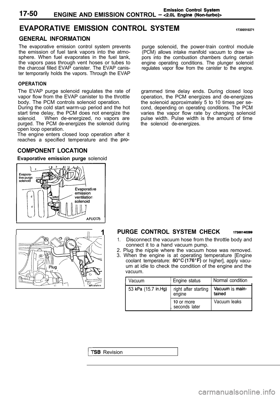
COMPONENT LOCATION
Evaporative emission purge solenoidpurge solenoid, the power-train control module
(PCM) allows intake manifold vacuum to draw va-
pors into the combustion chambers during certain
engine operating conditions. The plunger solenoid
regulates vapor flow from the canister to the engin e.
grammed time delay ends. During closed loop
operation, the PCM energizes and de-energizes
the solenoid approximately 5 to 10 times per se-
cond, depending on operating conditions. The PCM
varies the vapor flow rate by changing solenoid
pulse width. Pulse width is the amount of time
the solenoid de-energizes.
Revision
I 1PURGE CONTROL SYSTEM CHECK
1.Disconnect the vacuum hose from the throttle body a nd
connect it to a hand vacuum pump.
2. Plug the nipple where the vacuum hose was remove d.
3. When the engine is at operating temperature [Eng ine
coolant temperature: or higher], apply vacu-
um at idle to check the condition of the engine and the
vacuum.
Vacuum Engine status Normal condition
53
(15.7 right after starting
engine is
or moreVacuum leaks
, seconds later
Page 792 of 2103
ENGINE AND EMISSION CONTROL
ENGINE COOLANT TEMPERATURE SENSOR
AND INTAKE AIR TEMPERATURE SENSOR
To check these parts, refer to GROUP Troubleshooting.
AIR CONDITIONING SWITCH17300200031
To check the air conditioning switch, refer to GROU P 55
Air Conditioning Switch.
TSB Revision
Page 808 of 2103
17-68ENGINEAND EMISSION CONTROL (Turbo) and
EVAPORATIVE EMISSION CONTROL, SYSTEM
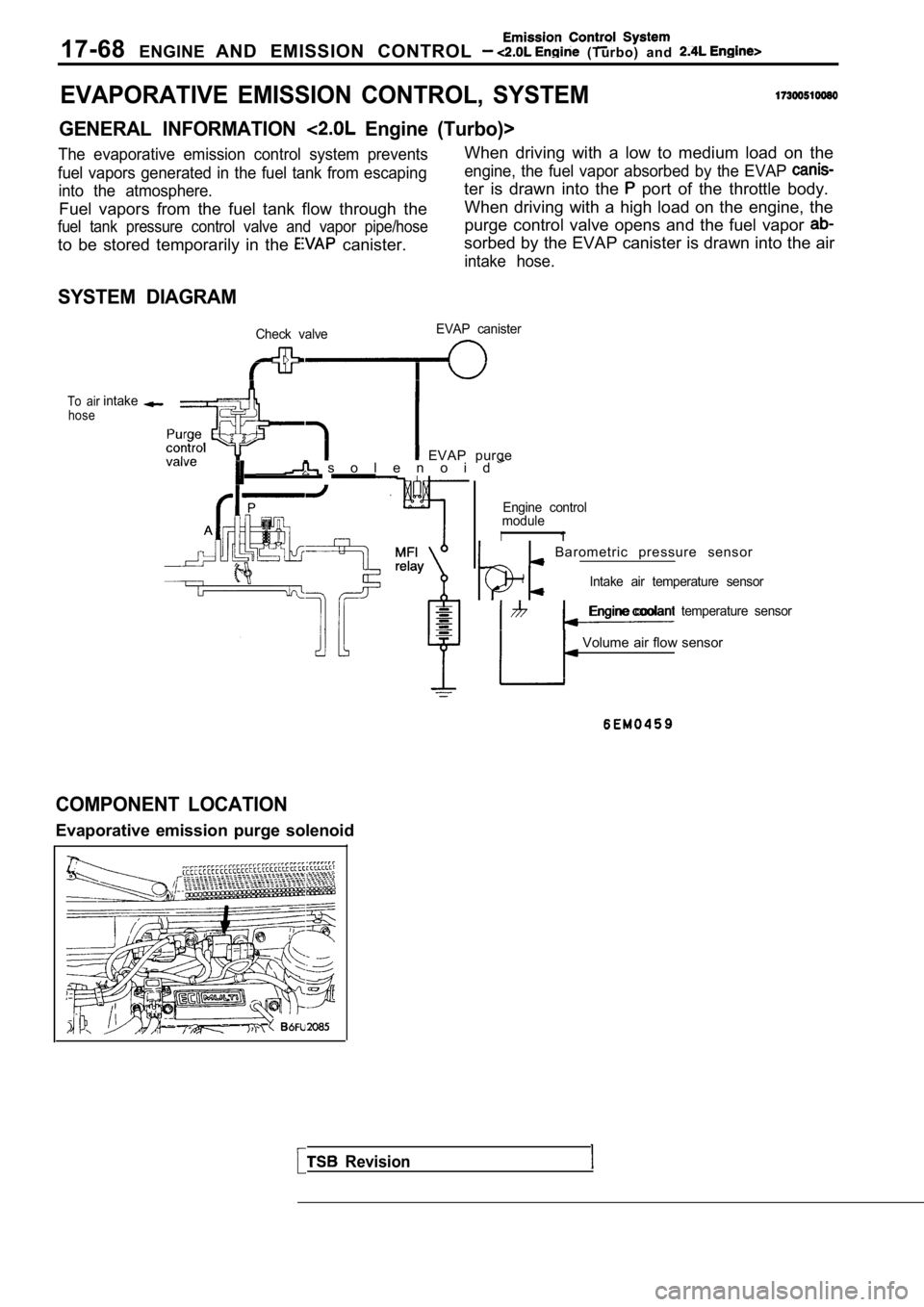
GENERAL INFORMATION Engine (Turbo)>
The evaporative emission control system preventsWhen driving with a low to medium load on the
fuel vapors generated in the fuel tank from escapin gengine, the fuel vapor absorbed by the EVAP
into the atmosphere.ter is drawn into the port of the throttle body.
Fuel vapors from the fuel tank flow through the When driving with a high load on the engine, the
fuel tank pressure control valve and vapor pipe/hos
epurge control valve opens and the fuel vapor
to be stored temporarily in the canister.sorbed by the EVAP canister is drawn into the air
intake hose.
SYSTEM DIAGRAM
Check valve EVAP canister
To air
hoseintake
EVAP purge s o l e n o i d
Revision
Engine control
module
I1
Barometric pressure sensor
Intake air temperature sensor
Engine coolant temperature sensor
Volume air flow sensor
COMPONENT LOCATION
Evaporative emission purge solenoid