Page 809 of 2103

(Turbo) and
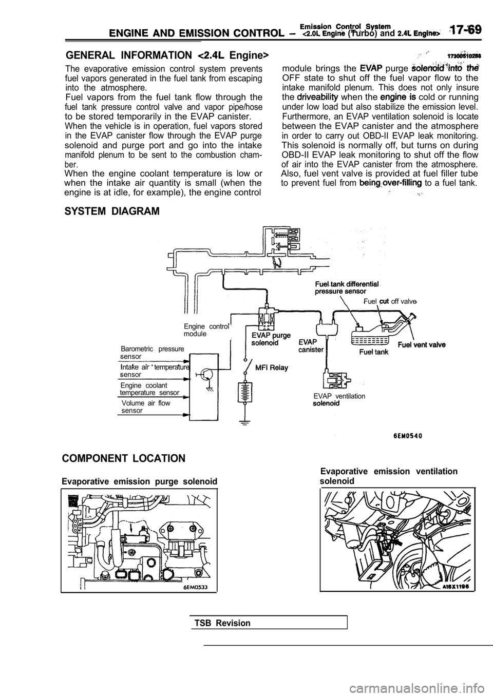
GENERAL INFORMATION Engine>
The evaporative emission control system prevents
fuel vapors generated in the fuel tank from escapin g
into the atmosphere.
Fuel vapors from the fuel tank flow through the
fuel tank pressure control valve and vapor pipe/hos e
to be stored temporarily in the EVAP canister.
When the vehicle is in operation, fuel vapors stored
in the EVAP canister flow through the EVAP purge
solenoid and purge port and go into the intake
manifold plenum to be sent to the combustion cham-
ber.
When the engine coolant temperature is low or
when the intake air quantity is small (when the
module brings the purge
OFF state to shut off the fuel vapor flow to the
intake manifold plenum. This does not only insure
the when the cold or running
under low load but also stabilize the emission leve l.
Furthermore, an EVAP ventilation solenoid is locate
between the EVAP canister and the atmosphere
in order to carry out OBD-II EVAP leak monitoring.
This solenoid is normally off, but turns on during
OBD-II EVAP leak monitoring to shut off the flow
of air into the EVAP canister from the atmosphere.
Also, fuel vent valve is provided at fuel filler tu be
to prevent fuel from to a fuel tank.
engine is at idle, for example), the engine control
SYSTEM DIAGRAM
Fuel off valve
Engine control
module
Barometric pressure
sensor
Intake air temperature
sensor
Engine coolant
temperature sensor
Volume air flow
sensorEVAP ventilation
COMPONENT LOCATION
Evaporative emission purge solenoid
Evaporative emission ventilation
solenoid
TSB Revision
Page 810 of 2103
17-70 CONTROL (Turbo) and Engine>
PURGE CONTROL SYSTEM CHECK (PURGE FLOW CHECK)
ENGINE (TURBO)>
Intake manifold plenum
EVAP purgesolenoid(ON: OPEN)
Nipple
Purgecontrolvalve
Check valve Air cleaner
Air intake hose
Purge flow
indicator
700)
1.Disconnect the purge hose from the evaporative emis sion
(EVAP) canister, and connect the special tool (purg e flow
indicator) between the EVAP canister and the purge hose.
2. The vehicle should be prepared as follows before the
inspection and adjustment.
lEngine coolant temperature: F)
l Lights, cooling fan and accessories: OFF
l Transaxle: Neutral (A/T for
range)
3. Run the engine at idle for 3 minutes or more.
Revision
Page 812 of 2103
(Turbo) and Engine>
PURGE CONTROL CHECK (PURGE FLOW CHECK)
ENGINE>17300140272
IntakeplenumThrottle body
From air cleaner
OFF
ON EVAP purge
solenoid
(ON: OPEN)
hose IPurge flow
indicator
Revision
EVAP canister
Disconnect the purge hose from the evaporative emis sion
(EVAP) canister, and connect the special tool (purg e flow
indicator) between the EVAP canister and the purge hose.
2. The vehicle should be prepared as follows before the
inspection and adjustment.
lEngine coolant temperature:
l Lights, cooling fan and accessories: OFF
l Transaxle: Neutral (A/T for
range)
3. Run the engine at idle for 4 minutes or more.
Page 816 of 2103
AND C O N T R O L (Turbo) and Engine>
Valve
PURGE CONTROL VALVE Engine
1. Remove the purge control valve.
2. Connect a hand vacuum pump to the vacuum nipple of the purge control valve.
3.Apply a vacuum of 53 (16 and check
ness.
4.Blow in air lightly from the evaporative emission c anister
side nipple and check conditions as follows.
Hand vacuum pump vacu-
umNormal condition
0 (0 (No vacuumAir does not blow through
is applied)
27
(8.0 or more Air blow through
5. Connect a hand
vacuum pump to the positive pressure
nipple of the purge control valve.
6.Apply a vacuum of 53 (16 and check
ness.
Revision
VOLUME AIR FLOW SENSOR, ENGINE COOLANT
TEMPERATURE SENSOR AND INTAKE AIR
TEMPERATURE SENSOR
Refer to GROUP Troubleshooting.
AIR CONDITIONING SWITCH
Refer to GROUP 55 Air Conditioning Switch.
Page 820 of 2103

(Turbo) and Engine>
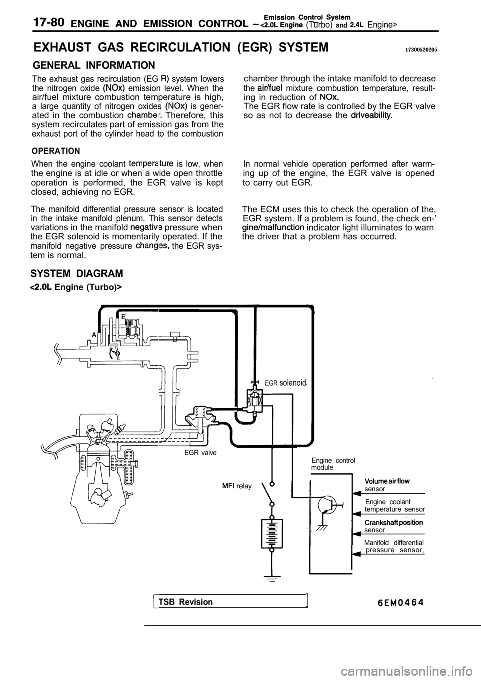
EXHAUST GAS RECIRCULATION
GENERAL INFORMATION
The exhaust gas recirculation (EG system lowers
the nitrogen oxide
emission level. When the
air/fuel mixture combustion temperature is high,
a large quantity of nitrogen oxides is gener-
ated in the combustion Therefore, this
system recirculates part of emission gas from the
exhaust port of the cylinder head to the combustion
OPERATION
When the engine coolant is low, when
the engine is at idle or when a wide open throttle
operation is performed, the EGR valve is kept
closed, achieving no EGR.
The manifold differential pressure sensor is locate d
in the intake manifold plenum. This sensor detects
variations in the manifold pressure when
the EGR solenoid is momentarily operated. If the
manifold negative pressure the EGR sys-
tem is normal.
SYSTEM DIAGRAM
Engine (Turbo)>
(EGR) SYSTEM17300520205
chamber through the intake manifold to decrease
the mixture combustion temperature, result-
ing in reduction of
The EGR flow rate is controlled by the EGR valve
so as not to decrease the
In normal vehicle operation performed after warm-
ing up of the engine, the EGR valve is opened
to carry out EGR.
The ECM uses this to check the operation of the, EGR system. If a problem is found, the check en-’
indicator light illuminates to warn
the driver that a problem has occurred.
EGR valve
relay
EGRsolenoid
Engine control
module
Isensor
Engine coolant
temperature sensor
sensor
Manifold differential
TSB Revision
pressure sensor,
Page 823 of 2103

Emission Control
ENGINE AND EMISSION CONTROL Engine
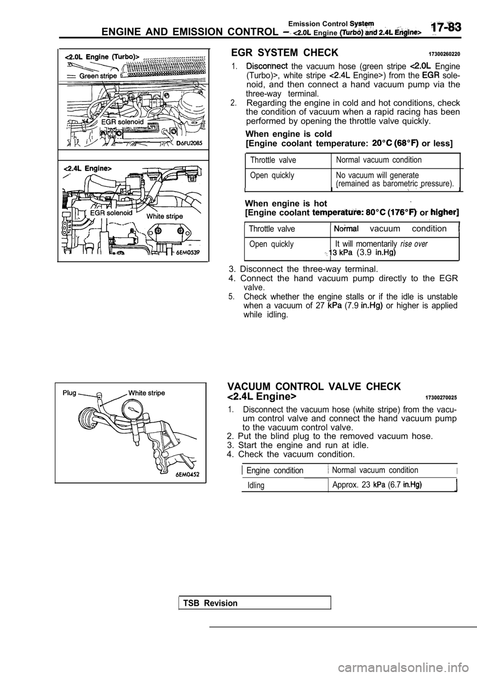
EGR SYSTEM CHECK17300260220
1. the vacuum hose (green stripe Engine
(Turbo)>, white stripe
Engine>) from the sole-
noid, and then connect a hand vacuum pump via the
three-way terminal.
2.Regarding the engine in cold and hot conditions, ch eck
the condition of vacuum when a rapid racing has bee n
performed by opening the throttle valve quickly.
When engine is cold [Engine coolant temperature:
or less]
Throttle valve
Open quickly Normal vacuum condition
No vacuum will generate
(remained as barometric pressure).
I
When engine is hot
[Engine coolant or
Throttle valve vacuum condition
Open quicklyIt will momentarily rise over
(3.9
3. Disconnect the three-way terminal.
4. Connect the hand vacuum pump directly to the EGR
valve.
5.Check whether the engine stalls or if the idle is u nstable
when a vacuum of 27
(7.9 or higher is applied
while idling.
VACUUM CONTROL VALVE CHECK
Engine>17300270025
1.Disconnect the vacuum hose (white stripe) from the vacu-
um control valve and connect the hand vacuum pump
to the vacuum control valve.
2. Put the blind plug to the removed vacuum hose.
3. Start the engine and run at idle.
4. Check the vacuum condition.
Engine condition Normal vacuum conditionI
IdlingApprox. 23 (6.7
TSB Revision
Page 1072 of 2103

AUTOMATIC TRANSAXLE
ENGINE (TURBO) AND On-vehicle Service
Stall test consists of determining maximum engine speed
obtained at full throttle in positions. This test
checks torque converter overrunning clutch operation,
and holding ability of transmission clutches and
brake.
Caution
During this test, make sure no stands in front
of, or behind, vehicle.
1.Check the transmission fluid level, fluid temperatu re and
coolant temperature.
lFluid level: At “HOT” position on dipstick
l Fluid temperature:
lEngine coolant temperature:
2. Apply chocks to both rear wheels.
3.
engine tachometer.
4. Apply parking and service brakes fully.
5 . S t a r t e n g i n e .
6. With selector lever in position, depress accelerator
pedal fully to read engine
rpm. Do not hold
throttle wide open any longer than is necessary to obtain
maximum engine rpm reading, and never longer
5 seconds at a time. If more than one stall test is required,
operate at approximately 1,000 in neutral
for 2 minutes to cool transmission fluid between te sts.
Standard value:
TSB Revision
2,100 2,600
3 , 3 0 0 3 , 6 0 0
7.Place selector lever to position and perform test
by the same procedures above.
Stall Speed Above Specification in
If stall speed is higher than Specification, rear c lutch or overrun-
ning clutch is slipping. In this case, perform hydrau-
lic test to locate cause of slippage.
Stall Above Specification in “R”
If stall speed is higher than front clutch of trans-
axle or low-reverse brake is In this perform
hydraulic test to locate cause of slippage.
Stall Speed Above Specification and “R”
If stall speed is lower than insufficient engine
output or faulty torque converter is Check for en-
gine misfiring, ignition timing, valve clearance etc. If these
are good, torque converter is faulty..
Page 1163 of 2103
AUTOMATIC TRANSAXLE
ENGINE (NON-TURBO)>
INSPECTION MATRIX FOR TROUBLE SYMPTOMS
PROBABLE CAUSE
No.Probable cause
Engine performance
2Worn or faulty underdrive clutch
3Worn of faulty overdrive clutch
4Worn of faulty reverse clutch
5Worn or faulty 2-4 clutch
6Worn or faulty low/reverse clutch
7 dragging
8Insufficient clutch plate clearance
9Damaged clutch seal
10Worn or damaged accumulator sealing(s)
11Faulty cooling system
12Engine coolant temperature too low
13Incorrect gear shift control linkage adjustment
14Shift linkage damaged
15Chipped or damaged gear teeth
16Planetary gear sets broken or seized
17Bearings worn or damaged
,
. .
,
TSB Revision