1989 MITSUBISHI GALANT check engine light
[x] Cancel search: check engine lightPage 445 of 1273
r
FUEL SYSTEM
of
MFI Components13-303
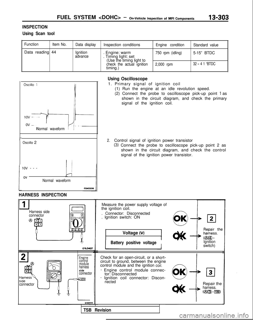
INSPECTION
Using Scan tool
Function Item No.
Data reading 44
Data displayInspection conditionsEngine condition Standard value
Ignition
advance
. Engine: warm
. Timing light: set750 rpm (idling)5-15” BTDC
(Use the timing light to
check the actual ignition 2,000 rpm32 - 4 1 “BTDCtiming.)
Oscillo 1
Normal waveform
Oscilio 2
!
1ov --
-
ovNormal waveform
HARNESS INSPECTION
Harness side
connectorE 0-0
J
El0
connectorI
lEnginecontrol
module
harness
sideconnector
Using Oscilloscope
1. Primary signal of ignition coil
(1) Run the engine at an idle revolution speed.
(2) Connect the probe to oscilloscope pick-up point
1 as
shown in the circuit diagram, and check the primary
signal of the ignition coil.
2.Control signal of ignition power transistor
(3) Connect the probe to oscilloscope pick-up point 2 as
shown in the circuit diagram, and check the control
signal of the ignition power transistor.
Measure the power supply voltage ofthe ignition coil.
. Connector: Disconnected. Ignition switch: ON
Voltage (VI
IBattery positive voltageIIIgnitionswitch)
Check for an open-circuit, or a
short-circuit to ground, between the engine
control module and the ignition coil.
* Engine control module connec- tor: Disconnected
* Ignition coil connector: Discon-nected
i
Repair theharness.
N23l3k-m)
TSB Revision
Page 458 of 1273
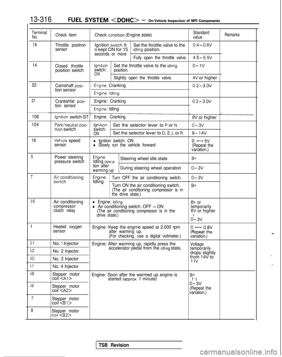
13-316FUEL SYSTEM
Inspection
of
MFI
Components
TerminalNo.Check itemCheck condition (Engine state)Standardvalue
Remarks
19Throttle positronIgnition switch: ItSet the throttle valve to the0.4- 0.wsensorIS kept ON for 15seconds or moreidlrng position.
Fully open the throttle valve.4.5- 5.5v
14
Closed throttlelgnrtrono-1vposition switchswitch:Set the throttle valve to the idling
position.
ONSlightly open the throttle valve.4V or higher
22Camshaft posi-tion sensorEngine: Cranking0.2- 3.ov
Engine: ldlrng
21
Crankshfat posi-tion sensor Engine: Cranking0.2- 3.ov
Engine: Idling
108lgnrtion switch-STEngine: Cranking8V or higher
104
Park/neutral
pos-ition switchIgnitionSet the selector lever to P or N.o-3vswitch:ONSet the selector lever to D, 2, L or R.8- 14V
18Vehicle speedl Ignition switch: ON
sensorl Slowly run the vehicle forward0 - 5v(Repeat the
variation.)
5Power steering
pressure switchEngine:Idling opera-Steering wheel idle stateB+
tion afterwarming-upDuring steering wheel operationo-3v
7A&;;;ditioningEngine:Idling _Turn OFF the air conditioning switch.o-3v
Turn ON the air conditioning switch.B+
(The air conditioning compressor is in
the drive state.)
35Air conditioningl Engine: IdlingB+ orcompressor
clutch relayl Air conditioning switch: OFF -, ON(The air conditioning compressor is in the
temporarily
drive state.)6V or higher o’-
3v
1Heated oxygen
sensorEngine: Keep the engrne speed at 2.000 rpmafter warming up.
(For checking, use a digital voltmeter.)ke;atoZivariation.)
51No. 1 InjectorEngine: After warming up, rapidly press the
52No. 2 Injector accelerator pedal from the idlrng state,Voltage
temporarily
drops slightly
30No. 3 Injectorfrom 14V to1 IV.
51No. 4 Injector
j8
Stepper motorcoil
i9
Stepper motor0%
coil
variation.)
‘7Stepper motorcoil
8Stepper motorco11
TSB Revision
Page 459 of 1273
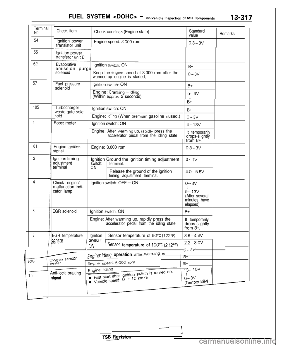
FUEL SYSTEM
Inspection
of MFI
Components13-317
TerminalNo.
54
55
62
57
105
I
01
2
i
E
Check item
Ignition power
transistor unit Check
condition (Engine state)
Engine speed:
3.000 rpm
Standardvalue
0.3- 3v
Remarks
Evaporativeemission purgeIgnition switch: ONB+
solenoidKeep the engrne speed at 3.000 rpm after thewarmed-up engine is started,o-3v
Fuel pressure
solenoidlgnltlon switch: ON
Engine:
Cranking - Idling(Within approx. 2 seconds)
B+
o- 3v1
B+
TurbochargerNaste gate sole-Ignition switch: ONB+ ioid
Engine: Idling (When premrum gasoline IS used.)0-3~
3oost meter
Ignition switch: ON4-13v
Engine: After warming up, rapldly press theaccelerator pedal from the idling state It temporarily
drops-slightlyIfrom B+.
Engine ignrtlonslgnalEngine: 3,000 rpm0.3-3v
lgnrtion timingadjustment
terminalIgnition Ground the ignition timing adjustment 0- 1Vswitch:terminal.ONRelease the ground of the ignition4.0- 5.5vtiming adjustment terminal.
Check engine/
malfunction indi- Ignition switch: OFF - ONo-3v
cator lamp9’- 13v(After several
minutes have
elapsed)
EGR solenoidIgnition switch: ONB+
Engine: After warming up, rapidly press theaccelerator pedal from the idling state. It temporarilydrops slightly
from B+.
EGR temperatureIgnitionSensor temperature of 50°C (122’F)3.6- 4.4V
rSt?MX
I
swlrcrl:nhir--.%?nY/V-_. ..sof temperature of 100°C (21.20~)2.2-3.0~
Engine: Idling operation after warming
UP
o-3v
B+
Engine &ed: 5.000 rPmB+
\ Anti-lock braking
signal
TSR Revision-
-
‘i
Page 540 of 1273
13-398
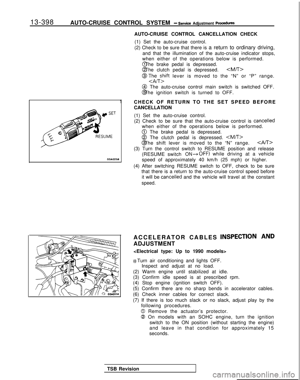
AUTO-CRUISE CONTROL SYSTEM - Setice Adjustment procedures
03*02.5*
1
AUTO-CRUISE CONTROL CANCELLATION CHECK
(1) Set the auto-cruise control.
(2) Check to be sure that there is a return to ordinary driving,
and that the illumination of the auto-cruise indicator stops,
when either of the operations below is performed. @ The brake pedal is depressed.
@ The clutch pedal is depressed.
@ TJhEzift lever is moved to the “N” or “P” range.
@I The auto-cruise control main switch is switched OFF.
@ The ignition switch is turned to OFF.
CHECK OF RETURN TO THE SET SPEED BEFORE
CANCELLATION (1) Set the auto-cruise control.
(2) Check to be sure that the auto-cruise control is
cancelled
when either of the operations below is performed.
@ The brake pedal is depressed.
@ The clutch pedal is depressed.
CAST>
(3) Turn the control switch to RESUME position and release
(RESUME switch
ON*OFF) while driving at a vehicle
speed of approximately 40 km/h (25 mph) or higher.
(4) After switching RESUME switch to OFF, check to be sure that there is a return to the auto-cruise control speed before
it will be
cancelled and the vehicle will travel at the constant
speed.
ACCELERATOR CABLES INSPECTION AND
ADJUSTMENT
(I) Turn air conditioning and lights OFF. Inspect and adjust at no load.
(2) Warm engine until stabilized at idle.
(3) Confirm idle speed is at prescribed rpm.
(4) Stop engine (ignition switch OFF).
(5) Confirm there are no sharp bends in accelerator cables.
(6) Check inner cables for correct slack.
(7) If there is too much slack or no slack, adjust play by the following procedures.
0 Remove the actuator’s protector.
0 On models with an SOHC engine, turn the ignition
switch to the ON position (without starting the engine)
and leave in that condition for approximately 15
seconds.
TSB Revision
Page 640 of 1273
17-20EMISSION CONTROL SYSTEMS -Evaporative Emission Control System
Engine speed (rpm)>
3FU262
E2id>
‘_/- )Engine
speed
(rpm)1 FU446
1 TSB Revision
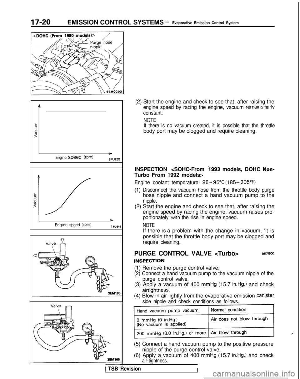
(2) Start the engine and check to see that, after raising the
engine speed by racing the engine, vacuum remains fairly
constant.
NOTE
If there is no vacuum created, it is possible that the throttle
body port may be clogged and require cleaning.
INSPECTION
Turbo From 1992 models>
Engine coolant temperature: 85- 95°C (185- 205°F)
(1) Disconnect the vacuum hose from the throttle body purge
hose nipple and connect a hand vacuum pump to the
nipple.
(2) Start the engine and check to see that, after raising the engine speed by racing the engine, vacuum raises pro-
portionately with the rise in engine speed.
NOTE
If there IS a problem with the change in vacuum, ‘it is
possible that the throttle body port may be clogged and
require cleaning.
PURGE CONTROL VALVE
INSPECTION
Ml7B.X
(1) Remove the purge control valve.
(2) Connect a hand vacuum pump to the vacuum nipple of the
purge control valve.
(3) Apply a vacuum of 400 mmHg (15.7 in.Hg.) and check
airtightness.
(4) Blow in air lightly from the evaporative emission Canister
side nipple and check conditions as follows.
(5) Connect a hand vacuum pump to the positive pressure
nipple of the purge control valve.
(6) Apply a vacuum of 400
mmHg (15.7 in.Hg.) and check
air-tightness.
I
Page 645 of 1273
EMISSION CONTROL SYSTEMS -Exhaust Gas Recirculation (EGR) System17-25
.
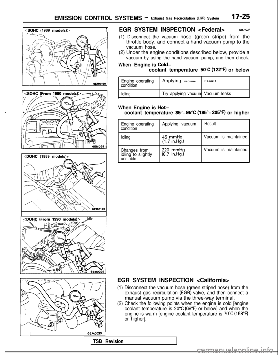
EGR SYSTEM INSPECTION
(1) Disconnect the vacuum hose (green stripe) from the throttle body, and connect a hand vacuum pump to the
vacuum hose.
(2) Under the engine conditions described below, provide a
vacuum by using the hand vacuum pump, and then check.
WhenEngine is Cold-
coolant temperature 50°C (122°F) or below
Engine operatingconditionApplying vacuumResul
t
IdlingTry applying vacuum Vacuum leaks
When Engine is Hot-
coolant temperature 85”-95°C (185”-205°F) or higher
Engine operatingconditionApplying vacuumResult
Idling45 mmHg(1.7 in.Hg.1Vacuum is maintained
Changes from
idling to slightlyunstable
Vacuum is maintained
EGR SYSTEM INSPECTION
(1) Disconnect the vacuum hose (green striped hose) from the exhaust gas recirculation
(EGR) valve, and then connect a
manual vacuum pump via the three-way terminal.
(2) Check the following points when the engine is cold [enginecoolant temperature is
20°C (68°F) or below] and when the
engine is warm [engine coolant temperature is
70°C (158°F)
or higher].
116EMOZW
TSB Revision
Page 674 of 1273
22-10MANUAL TRANSAXLE
e
TRANSAXLE
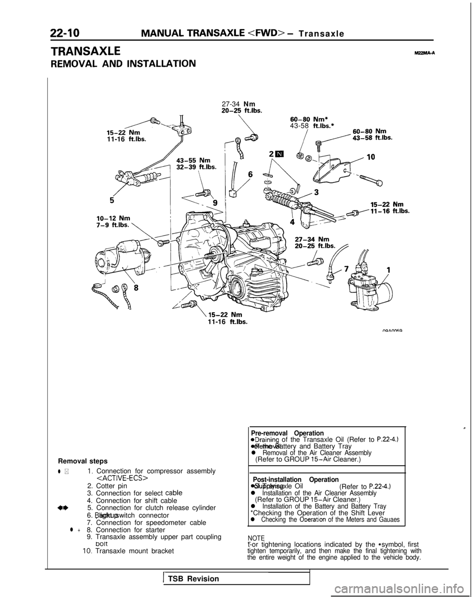
REMOVAL AND INSTALLATION
MZMA-A
27-34 Nm20-25 ft.lbs.
60-80
Nm*
43-58 ft.lbs.*
11-16
ft.lbs.71
11-16 ftlbs.
Removal steps
l *1, Connection for compressor assembly
2. Cotter pin
3. Connection for select cable
4. Connection for shift cable
a*5. Connection for clutch release cylinder
6. backup light switch connector
7. Connection for speedometer cable
l +8. Connection for starter
9. Transaxle assembly upper part coupling
tJ01t10. Transaxle mount bracket
Pre-removal Operation@Draining of the Transaxle Oil (Refer to P.22-4.) *Removal of the Battery and Battery Tray
l Removal of the Air Cleaner Assembly(Refer to GROUP 15-Air Cleaner.)
Post-installation Operation
asupplying of Transaxle Oil
(Refer to P.224.)l Installation of the Air Cleaner Assembly(Refer to GROUP 15-Air Cleaner.)l Installation of the Battery and Battery Tray*Checking the Operation of the Shift Leverl Checking the Ooeration of the Meters and Gauaes
NOTE
-t-or tightening locations indicated by the * symbol, firsttighten temporarily, and then make the final tightening with
the entire weight of the engine applied to the vehicle body.
1TSB Revision
Page 684 of 1273
22-20MANUAL TRANSAXLE
TRANSAXLE
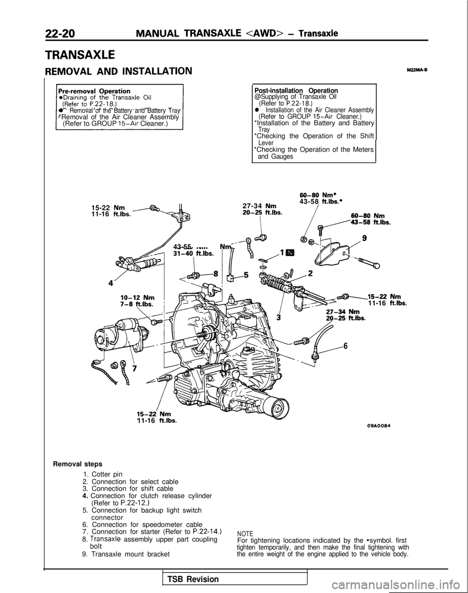
REMOVAL AND INSTALLATIONMZMA-B
l Removal of the Battery and Battery Tray*Removal of the Air Cleaner Assembly
(Refer to GROUP 15-Air Cleaner.)
15-22
Nm11-16 ft.lbs.-
lo-12 Nm7-8 ft.lbs.;
Post-installation Operation@Supplying of Transaxle Oil (Refer to P.22-18.)l Installation of the Air Cleaner Assembly(Refer to GROUP 15-Air Cleaner.)*Installation of the Battery and BatteryTray*Checking the Operation of the ShiftLever*Checking the Operation of the Metersand Gauges
60-80
Nm*
27-34
Nm43-58ft.lbs.*
20-25ft.lbs.60-80Nm
43-55 Nm _
15-22’ Nm11-16 ft.lbs.
6
-15-22 Nm11-16 ftlbs.
09AOOS4
Removal steps
1. Cotter pin
2. Connection for select cable
3. Connection for shift cable
4. Connection for clutch release cylinder (Refer to
P.22-12.)5. Connection for backup light switchconnector
6. Connection for speedometer cable
7. Connection for starter (Refer to
P.22-14.)8. ;,,:saxle assembly upper part coupling
9. Transaxle mount bracketNOTEFor tightening locations indicated by the * symbol. firsttighten temporarily, and then make the final tightening with
the entire weight of the engine applied to the vehicle body.
TSB Revision