1989 MITSUBISHI GALANT check engine light
[x] Cancel search: check engine lightPage 342 of 1273
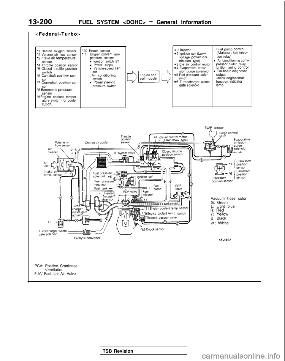
13-200FUEL SYSTEM
*l Heated oxygen sensor‘2 Volume air flow sensor*3 Intake air temperaturesensor‘4 Throttle position sensor‘5 Closed throttle positionswitch
*6
Camshaft posrtion sen-
sor
‘7 Crankshaft posrtion sen-
sor
‘8 Barometric pressuresensor “9
Engrne coolant temper-
ature swatch (for coolercut-off)
‘10 Knock sensor‘1 1Engien coolant
tem-perature sensorl lgnitton switch STl Power supplyl Vehicle-speed sen-sor. Arr conditioning
switch
l Power steeringpressure switch
Volume arrflow sensor
l 6
* 1 Injector. Fuel pump Control*2 Ignition coil (Low-(Multiport fuel injec-
voltage power-dis-tion relay)
tribution type) l Air conditioning com-
*3 Idle air control motor
pressor
clutch relay*4 Evaporative emis-
. Ignition timing control
sion purge solenoid l On-board diagnostic
*5 Fuel pressure sole-outputnoid. Check enginelmal-*6 Turbocharger wastegate solenoidf;r$ion indicator
EVAP canisterA
Throttle
9 Engine coolant temp. switch
Thermal VaCUUm valve
b;~ype; waste e-5 /I\- I”-
Catalyw converter
Vacuum hose color
G: Green
L: Light blue
R: RedY: Yellow
B: Black
W:
White
6FU1597
PCV: Positive CrankcaseVentilationFIAV Fast Idle Air Valve
I
TSB Revision
Page 343 of 1273
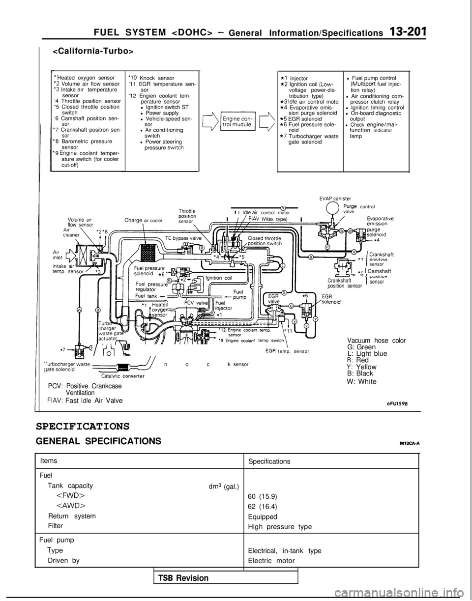
FUEL SYSTEM
I-
‘1 Heated oxygen sensor
‘2 Volume air flow sensor‘3 Intake arr temperature
sensor
‘4 Throttle position sensor
“5 Closed throttle position
switch
‘6 Camshaft position sen-
sor‘7 Crankshaft positron sen-sor‘8 Barometric pressure
sensor
‘9
Engrne coolant temper-
ature switch (for cooler
cut-off)
ArrInlet
lntaltern1
Volume airflow sensor
‘IO Knock sensor
‘11 EGR temperature sen- sor
‘12 Engien coolant tem- perature sensor
l Ignition switch ST
l Power supply
l Vehicle-speed sen- sor
l Air conditroningswitch
l Power steering pressure
swatch
Throttle
Charge air cooler posmon
sensor\\
*I Injector*2 Ignition coil (Low-
voltage power-dis-
tribution type)
*3 Idle air control moto*4 Evaporative emis- sion purge solenoid
*5 EGR solenoid*6 Fuel pressure sole-noid*7 Turbocharger waste
gate solenoid l Fuel pump control
(Multiport fuel injec-
tion relay)
l Air conditioning com- pressor clutch relay
l Ignition timing control
l On-board diaanostic
output
-l Check enginelmal-
function indicator
lamp
EVAxniy
&0
rurge controll 3ld,le,~ir control motor valve
,n/Evaporatrveemrssron
\tcln-^- temp. sensor
,Ir I-, . -,
sensor
7 ’ <‘I+c 1 Camshaft
Crankshaft1p”3111”I I
position sensorsensor
it
temp SWl,Ch\ -Vacuum hose color
t
WV:0 Knock sensor$bgha;ge;zte //
Catalyuc converter
G: Green
L: Light blue
R: RedY: Yellow
B: Black
PCV: Positive Crankcase
VentilationW: White
FIAV: Fast Idle Air Valve6FU1598
SPECIFICATIONS
GENERAL SPECIFICATIONSM13CA-A
Items
Fuel
Tank capacity
Return system
Filter
Fuel pump Type
Driven by Specifications
dm3 (gal.)
60 (15.9)
62 (16.4)
Equipped
High pressure type
Electrical, in-tank type
Electric motor
TSB Revision
Page 347 of 1273
FUEL SYSTEM
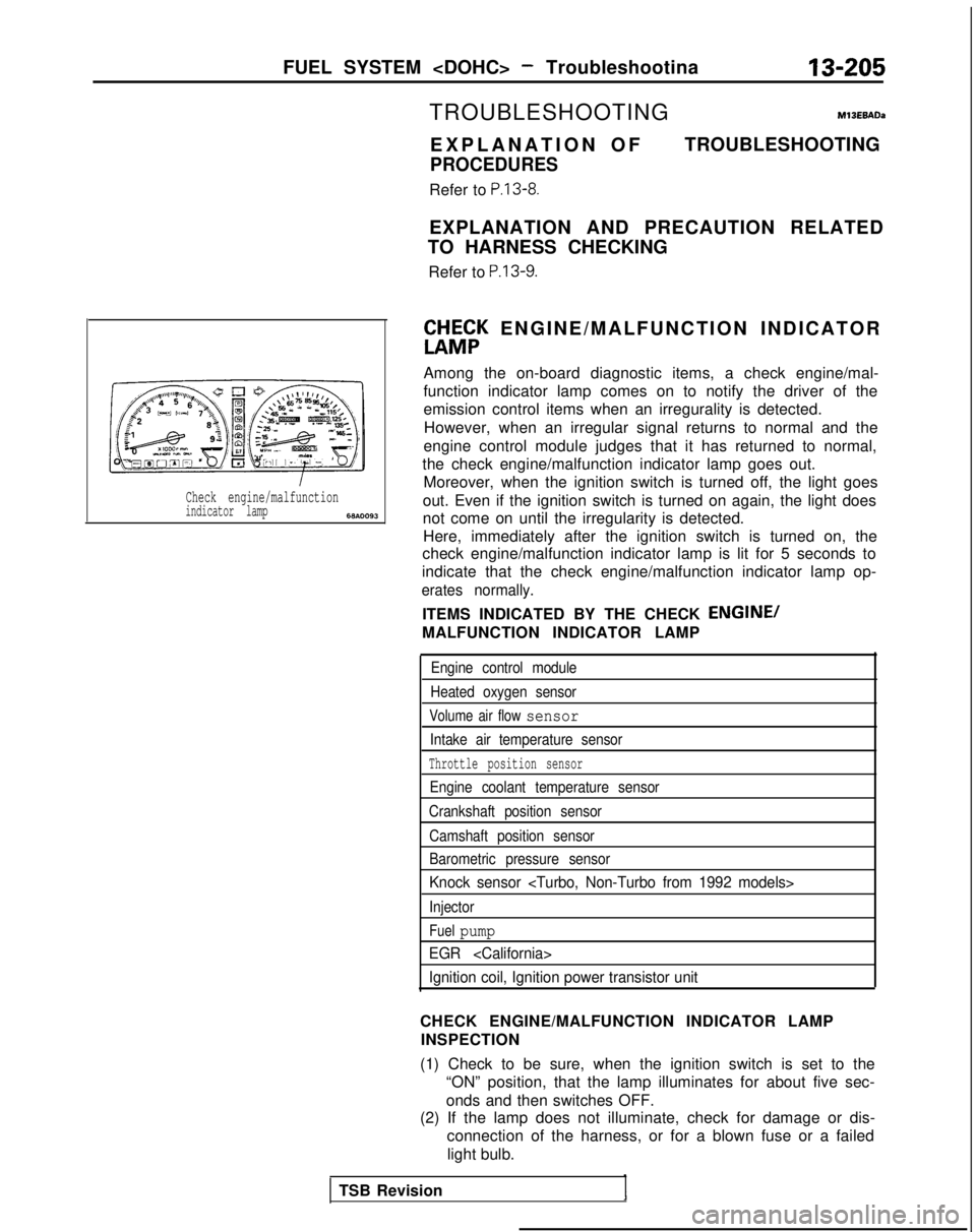
Check engine/malfunctionindicator lamp6w.0093
TROUBLESHOOTINGM13EBADa
EXPLANATION O
F
PROCEDURES
Refer to P.13-8.
TROUBLESHOOTING
EXPLANATION AND PRECAUTION RELATED
TO HARNESS CHECKING
Refer to
P.13-9.
ft&;K ENGINE/MALFUNCTION INDICATO
R
Among the on-board diagnostic items, a check engine/mal-
function indicator lamp comes on to notify the driver of the
emission control items when an irregurality is detected. However, when an irregular signal returns to normal and the
engine control module judges that it has returned to normal,
the check engine/malfunction indicator lamp goes out. Moreover, when the ignition switch is turned off, the light goes
out. Even if the ignition switch is turned on again, the light does
not come on until the irregularity is detected. Here, immediately after the ignition switch is turned on, the
check engine/malfunction indicator lamp is lit for 5 seconds to
indicate that the check engine/malfunction indicator lamp op-
erates normally.
ITEMS INDICATED BY THE CHECK ENGINE/
MALFUNCTION INDICATOR LAMP
Engine control module
Heated oxygen sensor
Volume air flow sensor
Intake air temperature sensor
Throttle position sensor
Engine coolant temperature sensor
Crankshaft position sensor
Camshaft position sensor
Barometric pressure sensor
Knock sensor
Injector
Fuel pump
EGR
Ignition coil, Ignition power transistor unit
CHECK ENGINE/MALFUNCTION INDICATOR LAMP INSPECTION
(1) Check to be sure, when the ignition switch is set to the “ON” position, that the lamp illuminates for about five sec-
onds and then switches OFF.
(2) If the lamp does not illuminate, check for damage or dis-
connection of the harness, or for a blown fuse or a failed
light bulb.
TSB Revision
Page 387 of 1273
FUEL SYSTEM
cl989 models> -a’i\.-upI t
SERVICE ADJUSTMENT PROCEDURES
CURB IDLE SPEED INSPECTION
MlSFHAB
(1) The vehicle should be prepared as follows before the inspection.
l Engine coolant temperature:
85-95°C (185-205°F)
l Lights, electric cooling fan and accessories: OFF
l Transaxle: Neutral
(P for vehicles with an automatic
transaxle)
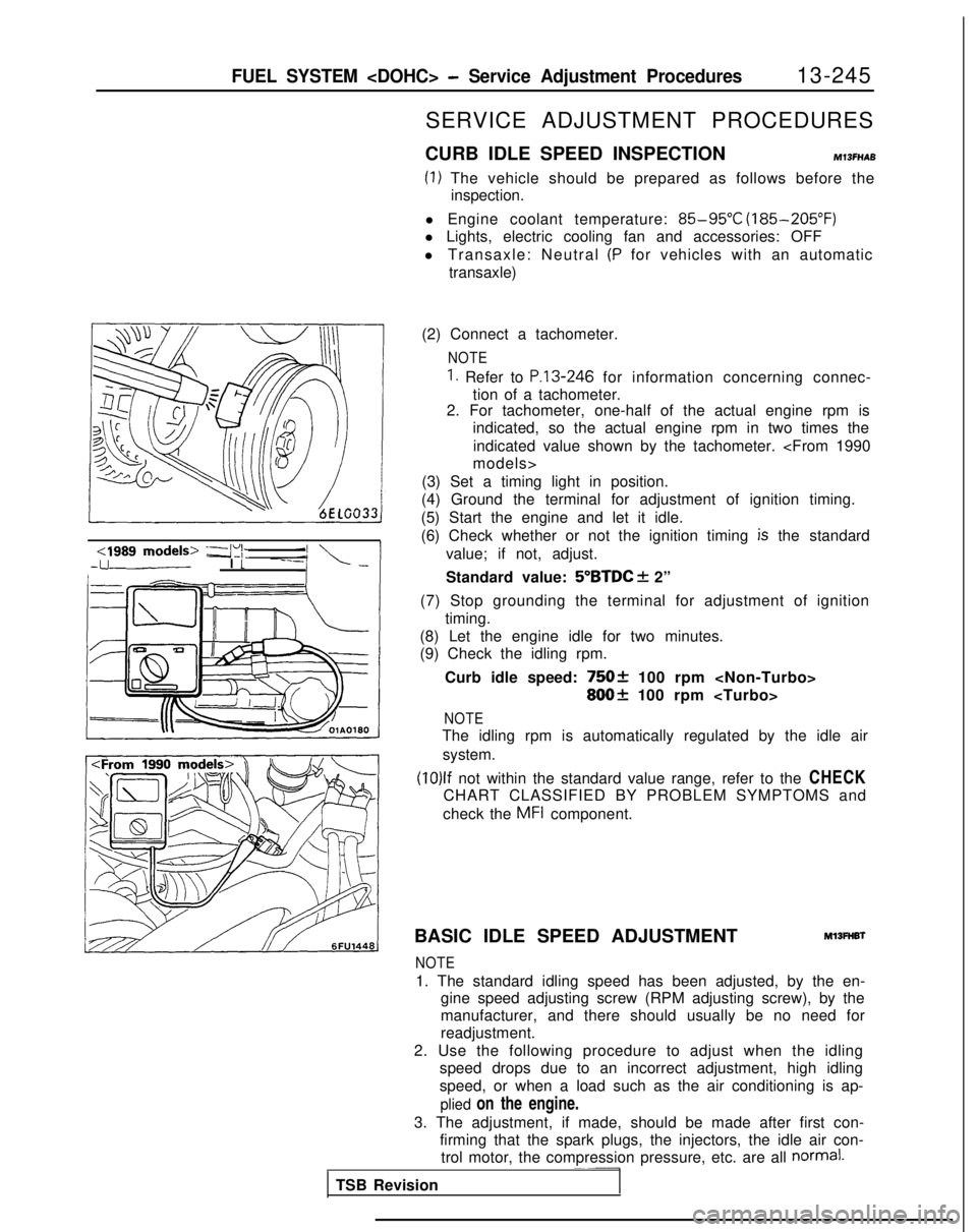
(2) Connect a tachometer.
NOTE
1. Refer to P.13-246 for information concerning connec-
tion of a tachometer.
2. For tachometer, one-half of the actual engine rpm is
indicated, so the actual engine rpm in two times the
indicated value shown by the tachometer.
(3) Set a timing light in position.
(4) Ground the terminal for adjustment of ignition timing.
(5) Start the engine and let it idle.
(6) Check whether or not the ignition timing
is the standard
value; if not, adjust.
Standard value:
5”BTDC f 2”
(7) Stop grounding the terminal for adjustment of ignition timing.
(8) Let the engine idle for two minutes.
(9) Check the idling rpm.
Curb idle speed:
75Ok 100 rpm
800+ 100 rpm
NOTE
The idling rpm is automatically regulated by the idle airsystem.
(10)lf not within the standard value range, refer to the CHECK
CHART CLASSIFIED BY PROBLEM SYMPTOMS and
check the
MFI component.
BASIC IDLE SPEED ADJUSTMENT
Ml3FHBl
NOTE
1. The standard idling speed has been adjusted, by the en- gine speed adjusting screw (RPM adjusting screw), by the
manufacturer, and there should usually be no need for
readjustment.
2. Use the following procedure to adjust when the idling speed drops due to an incorrect adjustment, high idling
speed, or when a load such as the air conditioning is ap-
plied on the engine.
3. The adjustment, if made, should be made after first con- firming that the spark plugs, the injectors, the idle air con-trol motor, the compression pressure, etc. are all
normal.~~-
TSB Revision
Page 390 of 1273
13-248FUEL SYSTEM
(8) Switch OFF the ignition switch.
(9) If the scan tool was not used, disconnect the jumper wire from the diagnostic test mode control terminal. (10)Disconnect
the jumper wire from the terminal for adjust-
ment of ignition timing, and return the connector to its
original condition.
(11
)Start the engine again and let it run at idle speed for about
ten minutes; check to be sure that the idling condition is
normal.
THROTTLE BODY (THROTTLE VALVE AREA)
CLEANING
Ml3ACL
(1) Start the engine and warm it up until the temperature of the engine coolant reaches
80°C (176°F) or higher; then stop
the engine.
(2) Disconnect the air intake hose at the throttle body side.
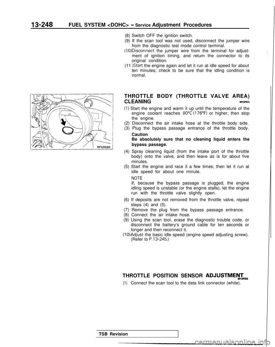
(3) Plug the bypass passage entrance of the throttle body.
Caution
Be absolutely sure that no cleaning liquid enters the
bypass passage.
(4) Spray cleaning liquid (from the intake port of the throttle body) onto the valve, and then leave as is for about five
minutes.
(5) Start the engine and race it a few times; then let it run at
idle speed for about one minute.
NOTE
If, because the bypass passage is plugged, the engine
idling speed is unstable (or the engine stalls), let the engine
run with the throttle valve slightly open.
(6) If deposits are not removed from the throttle valve, repeat steps (4) and (5).
(7) Remove the plug from the bypass passage entrance.
(8) Connect the air intake hose.
(9) Using the scan tool, erase the diagnostic trouble code, or disconnect the battery’s ground cable for ten seconds or
longer and then reconnect it. (lO)Adjust
the basic idle speed (engine speed adjusting screw).
(Refer to
P.13-245.)
THROTTLE POSITION SENSOR ADJUSTMEyTmEE
(1)Connect the scan tool to the data link connector (white).
TSB Revision
Page 404 of 1273
13-262FUEL SYSTEM
INSPECTION
Using Scan tool
1 Data 12reading
L
Data displayInspection conditions
Sensor de-. Engine coolanttection airtemperature: 85-95°Cvolume (fre-(185-205°F)quency) .Lights, cooling fan, elec-trical accessories: OFF. Transaxle: neutral (PJTmodels: “P” range)
Engine condition
Idling
2,000 rpm
Racing
Standard value 25-50
Hz
60-90 Hz
Frequency increases as
racing rpm increases.
NOTEThe volume air flow sensor output frequency may be about 10% higher than\
indicated above when the vehicle is new
[driven approximately 500 km(300 miles) or less].
i
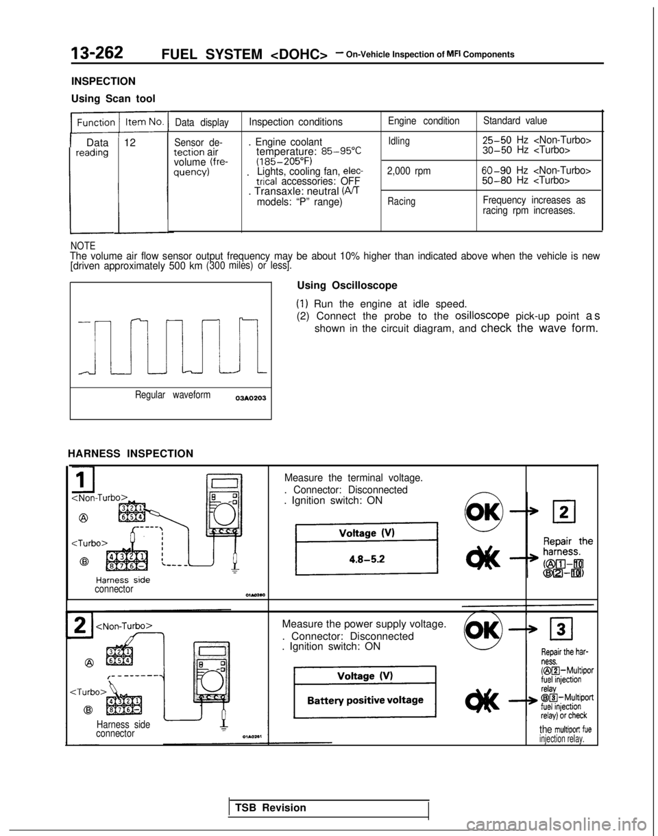
Regular waveform03AO203
HARNESS INSPECTION Using Oscilloscope
(1) Run the engine at idle speed.
(2) Connect the probe to the osilloscope
pick-up point as
shown in the circuit diagram, and check the wave form.
Measure the terminal voltage.
. Connector: Disconnected
. Ignition switch: ON
connectorOlMaa
Measure the power supply voltage.
. Connector: Disconnected
. Ignition switch: ON
Harness side
connectorthe multiport fueinjection relay.
TSB Revision
Page 438 of 1273
13-296FUEL SYSTEM
Inspection
of
MFI
Components
INSPECTION
Using Scan tool
Function Item No. Data displayInspection conditionsEngine coolant temperature Standard value1
Data 41;ctJ$onEngine crankingAt 0°C (32”F)*2Approx. 17 ms
readingApprox. 40 ms
At 20°C (68°F)Approx. 38 ms
Approx. 19 ms
At 80°C (176°F)Approx. 9 ms
Approx. 4.5 ms
Function
Datareading
3TE Item No.
41
Data display
$ctX$on
Inspection conditionsEngine condition
Standard value
. Engine coolant tempera-Idling2.4-3.2 ms
ture:1.6-2.6 ms
(185-205°F)
. Lights, cooling fan, electric- 2,000 rpm1.9-2.9
ms
al accessories: OFF1.4-2.2 ms
+l:The injector activation time indicates the time under the following cond\
itions: a power source voltage of 11V and acranking rpm of 250 rpm or less.*2: Simultaneous injection at four cylinders when engine coolant temperatur\
e is 0°C (32°F).*3: The injector activation time may be about 10% longer than indicated abo\
ve when the vehicle is new [driven
approximately 500 km (300 miles) or less].
Function Item No.Description Inspection conditionsNormal indication
Actuator test 01No. 1 injector is shut off.
Engine: idling after warmThe idling condition
02No. 2 injector is shut off.?!hut off the injectors inchanges more.
(Either becomes more un-
03
No. 3 injector is shut off.
04
No.4 injector is shut off.
sequence during after
engine warm-up, check
the idling condition.) stable, or engine stalls.)
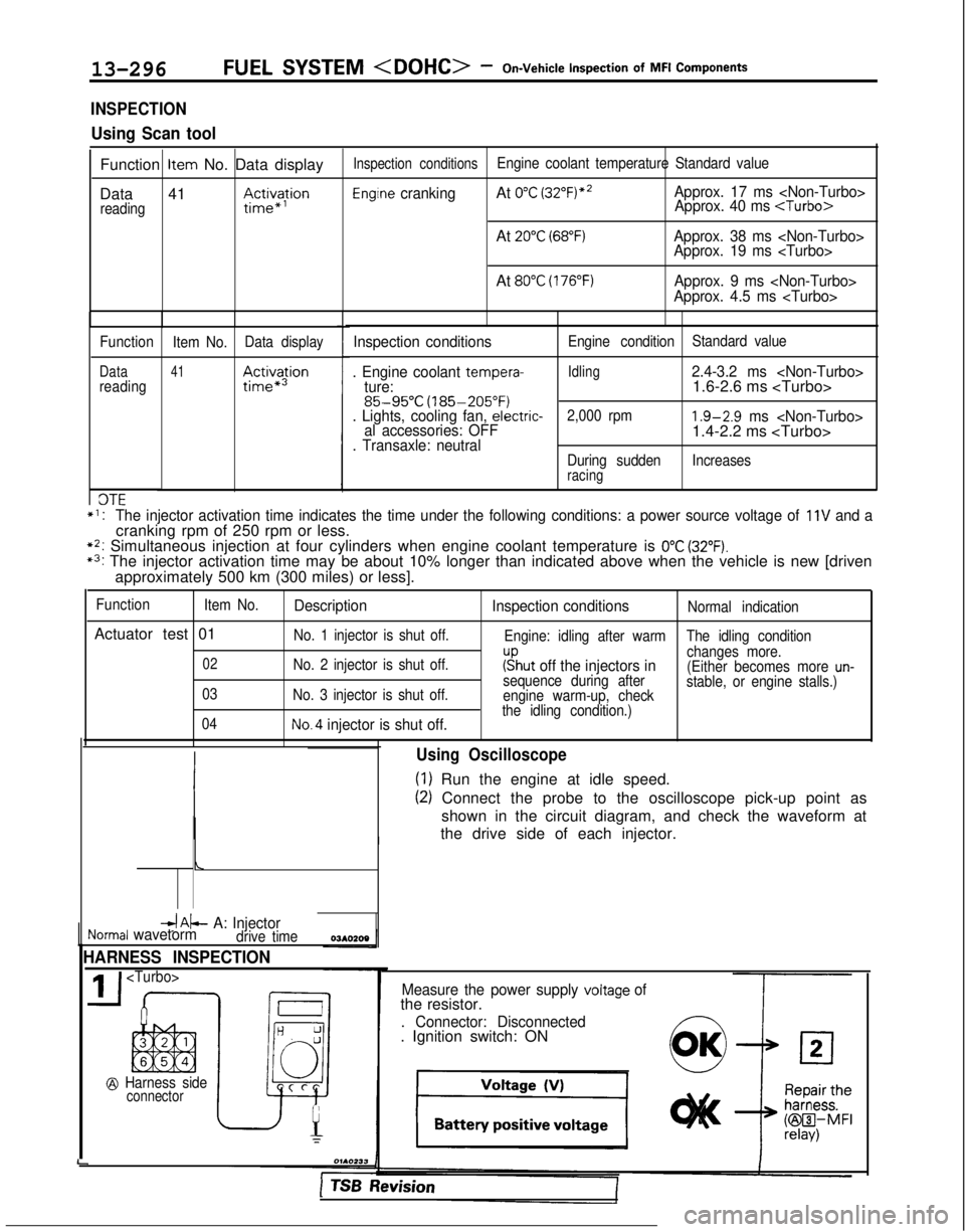
,d&- A: InjectorNormal wavetormdrive time
HARNESS INSPECTION
@ Harness sideconnector
I
L
Using Oscilloscope
(1) Run the engine at idle speed.
(2) Connect the probe to the oscilloscope pick-up point as
shown in the circuit diagram, and check the waveform at
the drive side of each injector.
Measure the power supply voltage ofthe resistor.
. Connector: Disconnected. Ignition switch: ON
1 TSB hevision
Page 441 of 1273
FUEL SYSTEM
MFI Components13-299
OPERATION
l The amount of air taken in during idling is
regulated by the opening and closing of the
servo valve located in the air passage that
bypasses the throttle valve.
l The servo valve is opened or closed by the
activation of the stepper motor (incorporated
within the idle air control motor) in the forward
or reverse direction.
TROUBLESHOOTING HINTS
Hint 1: If the number of stepper motor steps increases to
IOO- 120 steps or decreases
to 0 step, the cause may be presumed to be a malfunction of the stepper motor or
damaged or disconnected wiring of the
harness.
Hint 2: If the number of stepper motor steps
deviates from the standard value even
though the results of the checking of the
harness of the idle air control motor and of
the comoonent
itself indicate no abnormal
condition, the cause may be presumed to be one of the following.
INSPECTION
Using Scan tool
lBattery power supply is supplied, by way of the
multiport fuel injection relay, to the coil of the
stepper motor. The engine control module
switches ON the power transistors (located
within the engine control module) in sequential
order, and, when current flows to the stepper motor coil, the stepper motor is activated in the
forward or reverse direction.
(1) Improper adjustment of the standard
idling speed.
(2) Deposits adhered to the throttle valve.
(3) Leakage of air into the intake manifold
from a gasket gap, etc.
(4) Incomplete close contact of the EGRvalve seat.
(5) Incomplete combustion within the
cylinder.
(Malfunction of the spark plugs, the
ignition coil, the iniectors,
the
com- pression
pressure, etc.)
FunctionItem No.Data display Check conditions Load conditionsStandard value
Data reading 45Steppermotor steps. Engine coolant tempera-
. Air conditioning
4-14Step
ture:switch: OFF
(185-205°F)
. Lights, electrical cooling
:$b::pfan and accessories: OFF
. Transaxle: neutral
. Closed throttle switch: ON
- Air conditioning 20-60 Step
switch: ON
(The compressor clutchshould be activated when
the air conditioning switch;J-;;o~P
is switched ON.)* Engine: idling
1;:!,1;:!,
/!-I\/!-I\
f$&$:”f$&$:”
! ,‘,! ,‘,
4);4);
;jj\(Q(j!jGZ-);jj\(Q(j!jGZ-)
lili
q#Q~Hq#Q~HF]F]
ii 2 L J 2 L ~ -0SClllO 4ii 2 L J 2 L ~ -0SClllO 4
NOTE
When the vehicle is new (driven approximately 500 km (300 miles) or l\
ess) the number of steps may be about
30 steps greater than the standard value indicated above.
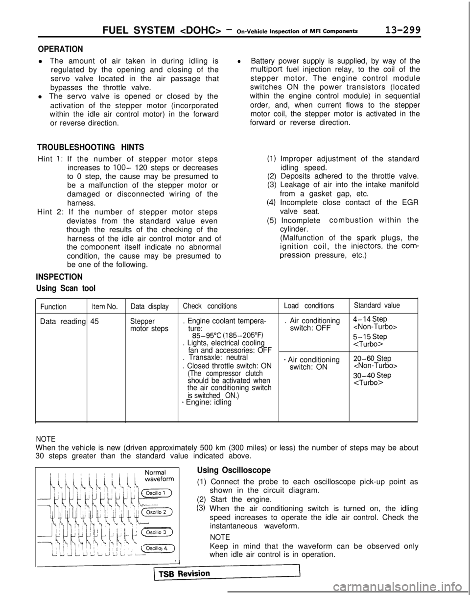
Using Oscilloscope
(1) Connect the probe to each oscilloscope pick-up point as
shown in the circuit diagram.
(2) Start the engine.
(3) When the air conditioning switch is turned on, the idling speed increases to operate the idle air control. Check theinstantaneous waveform.
NOTE
Keep in mind that the waveform can be observed only
when idle air control is in operation.