1989 MITSUBISHI GALANT check engine light
[x] Cancel search: check engine lightPage 1162 of 1273
![MITSUBISHI GALANT 1989 Service Repair Manual 35-42
SERVICE BRAKES - Anti-lock Braking System Troubleshooting
BABS warning light illuminated after the engine is started and remains on\
.
[Explanation]
This is the symptom when the ABS ECU does not MITSUBISHI GALANT 1989 Service Repair Manual 35-42
SERVICE BRAKES - Anti-lock Braking System Troubleshooting
BABS warning light illuminated after the engine is started and remains on\
.
[Explanation]
This is the symptom when the ABS ECU does not](/manual-img/19/57312/w960_57312-1161.png)
35-42
SERVICE BRAKES - Anti-lock Braking System Troubleshooting
BABS warning light illuminated after the engine is started and remains on\
.
[Explanation]
This is the symptom when the ABS ECU does not
power up due to broken ECU power circuit, etc.,
when the fail safe function operates and isolates the
system or when the warning light drive circuit is
short circuited.
[Hint]
Check the on-board diagnostic output and if there is
no output voltage or if the scan tool and ABS ECU
cannot communicate, there is a good possibility
that power is not flowing to the ECU.
Caution
l
If there is no output of diagnostic trouble
codes, there is a good possibility that the
fail safe is functioning.
MAINFUSIBLELINK @
IGNITION
SWITCH
(IG1)
ILOIE;NATION
+10
3
@izJ”,HUZ8 p:r12 /e-,
xx
I
I
I*I
; 16 4=
9
II
d
+qfimamq!2 a
I -LQ-7 ABS ECUm1
: Non-Turbo . Turbo: Non-Turbo
output? (Is there communi- NEXT PAGE
cation with scan tool?)
I
Yes
Does diagnostic troublecode output display normalcodes?
No . Check, using the diagnos-tic trouble code checkchart. (Refer to P.35-38.)IIILI
Short in harness betweenrgl;r ECU and ABS warning) Repair harness or replacecombination meter.
II
TSB Revision
Page 1174 of 1273
SERVICE BRAKES - Service Adjustment Procedures35-53
switch
switch
c/ 14F516
Pedal
Idown /
\ \
F14517
TSB Revision
F14518
SERVICE ADJUSTMENT PROCEDURES
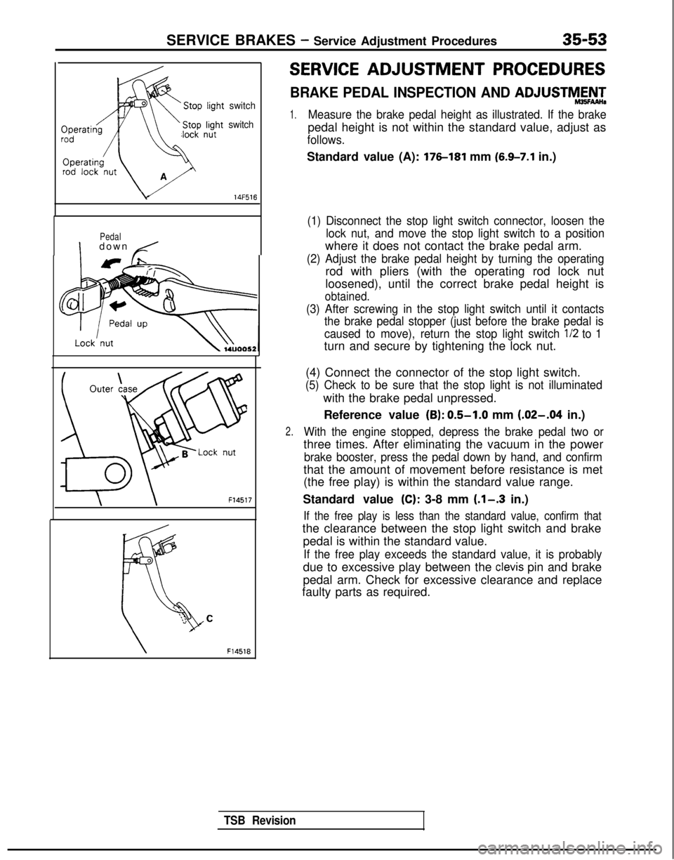
BRAKE PEDAL INSPECTION AND ADJUSTMAN-
1.Measure the brake pedal height as illustrated. If the brake
pedal height is not within the standard value, adjust as
follows.
Standard value (A): 176-181 mm (6.9-7.1 in.)
(1) Disconnect the stop light switch connector, loosen the
lock nut, and move the stop light switch to a position
where it does not contact the brake pedal arm.
(2) Adjust the brake pedal height by turning the operating
rod with pliers (with the operating rod lock nut
loosened), until the correct brake pedal height is
obtained.
(3) After screwing in the stop light switch until it contactsthe brake pedal stopper (just before the brake pedal is
caused to move), return the stop light switch l/2
to 1
turn and secure by tightening the lock nut.
2.
(4) Connect the connector of the stop light switch.
(5) Check to be sure that the stop light is not illuminated
with the brake pedal unpressed.
Reference value
(B): 0.5-1.0 mm (.02-.04 in.)
With the engine stopped, depress the brake pedal two or
three times. After eliminating the vacuum in the power
brake booster, press the pedal down by hand, and confirm
that the amount of movement before resistance is met
(the free play) is within the standard value range.
Standard value
(C): 3-8 mm (.l-.3 in.)
If the free play is less than the standard value, confirm that
the clearance between the stop light switch and brake pedal is within the standard value.
If the free play exceeds the standard value, it is probably
due to excessive play between the clevis pin and brake
pedal arm. Check for excessive clearance and replace
faulty parts as required.
Page 1175 of 1273
35-54SERVICE BRAKES - Service Adjustment Procedures
F14519
14UOO61
When engine isstopped
No good
0
w
\/‘14UOO62z;redengine
is
14UOO60 ,3.
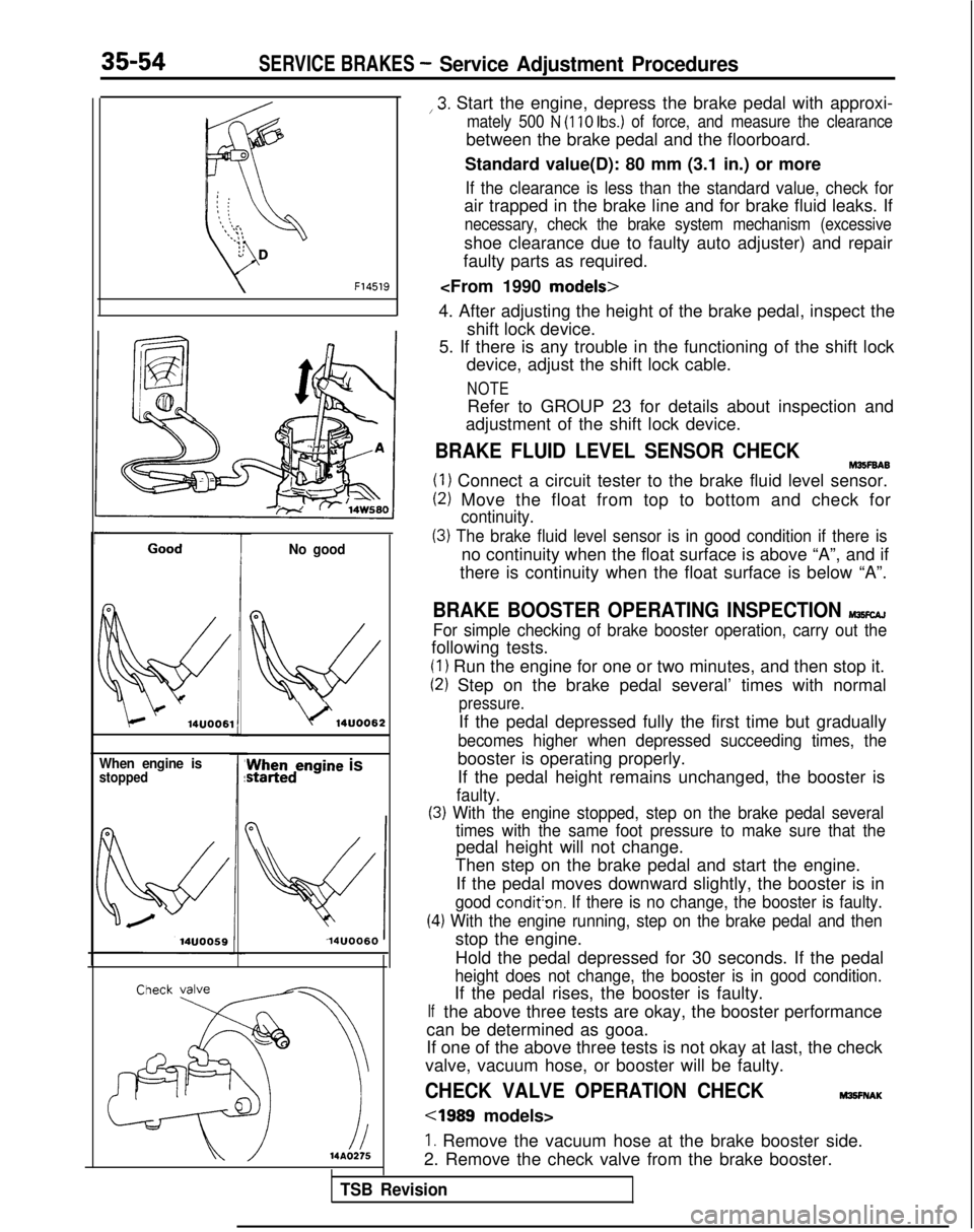
Start the engine, depress the brake pedal with approxi-
mately 500 N (110 Ibs.) of force, and measure the clearance
between the brake pedal and the floorboard.
Standard value(D): 80 mm (3.1 in.) or more
If the clearance is less than the standard value, check for
air trapped in the brake line and for brake fluid leaks. If
necessary, check the brake system mechanism (excessive
shoe clearance due to faulty auto adjuster) and repair
faulty parts as required.
4. After adjusting the height of the brake pedal, inspect the shift lock device.
5. If there is any trouble in the functioning of the shift lock device, adjust the shift lock cable.
NOTE
Refer to GROUP 23 for details about inspection and
adjustment of the shift lock device.
BRAKE FLUID LEVEL SENSOR CHECKM35F6A6
(1) Connect a circuit tester to the brake fluid level sensor.
(2) Move the float from top to bottom and check for
continuity.
(3) The brake fluid level sensor is in good condition if there is
no continuity when the float surface is above “A”, and if
there is continuity when the float surface is below “A”.
BRAKE BOOSTER OPERATING INSPECTION MlKcAJ
For simple checking of brake booster operation, carry out the
following tests.
(1) Run the engine for one or two minutes, and then stop it.
(2) Step on the brake pedal several’ times with normal
pressure.
If the pedal depressed fully the first time but gradually
becomes higher when depressed succeeding times, the
booster is operating properly.
If the pedal height remains unchanged, the booster is
faulty.
(3) With the engine stopped, step on the brake pedal several
(4
If
times with the same foot pressure to make sure that the
pedal height will not change.
Then step on the brake pedal and start the engine.
If the pedal moves downward slightly, the booster is in
good condit’on. If there is no change, the booster is faulty.
.) With the engine running, step on the brake pedal and then
stop the engine.
Hold the pedal depressed for 30 seconds. If the pedal
height does not change, the booster is in good condition.
If the pedal rises, the booster is faulty.
the above three tests are okay, the booster performance
can be determined as gooa.
If one of the above three tests is not okay at last, the check
valve, vacuum hose, or booster will be faulty.
CHECK VALVE OPERATION CHECKM3!3FNAK
cl989 models>
1. Remove the vacuum hose at the brake booster side.
2. Remove the check valve from the brake booster.
TSB Revision
Page 1189 of 1273
35-68SERVICE BRAKES - Service Adjustment Procedures
A.B.S. warning light
Ignition switch
sT;!i;%
lARD175
Filter4
kR
14A0171
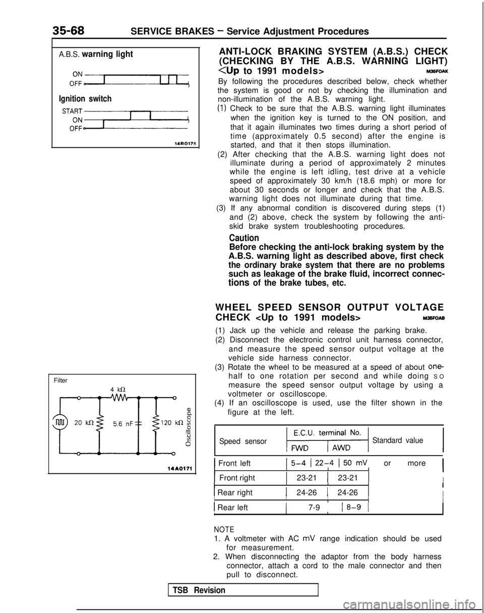
ANTI-LOCK BRAKING SYSTEM (A.B.S.) CHECK
(CHECKING BY THE A.B.S. WARNING LIGHT)
By following the procedures described below, check whether
the system is good or not by checking the illumination and non-illumination of the A.B.S. warning light.
(1) Check to be sure that the A.B.S. warning light illuminates
when the ignition key is turned to the ON position, and
that it again illuminates two times during a short period of
time (approximately 0.5 second) after the engine is started, and that it then stops illumination.
(2) After checking that the A.B.S. warning light does not illuminate during a period of approximately 2 minutes
while the engine is left idling, test drive at a vehicle
speed of approximately 30 km/h (18.6 mph) or more for
about 30 seconds or longer and check that the A.B.S.
warning light does not illuminate during that time.
(3) If any abnormal condition is discovered during steps (1) and (2) above, check the system by following the anti-
skid brake system troubleshooting procedures.
Caution
Before checking the anti-lock braking system by the
A.B.S. warning light as described above, first check
the ordinary brake system that there are no problems
such as leakage of the brake fluid, incorrect connec-
tions of the brake tubes, etc.
WHEEL SPEED SENSOR OUTPUT VOLTAGE
CHECK
M3sFoAE
(1) Jack up the vehicle and release the parking brake.
(2) Disconnect the electronic control unit harness connector,
and measure the speed sensor output voltage at the
vehicle side harness connector.
(3) Rotate the wheel to be measured at a speed of about
one-
half to one rotation per second and while doing S
O
measure the speed sensor output voltage by using a
voltmeter or oscilloscope.
(4) If an oscilloscope is used, use the filter shown in the
figure at the left.
Speed sensor1-1 Standard value
1 Front left15-4 (22-4 I50 mV or more 1IIIII
IFront rightI1 23-21 1 23-21 1IIIII1 Rear right1 24-26 1 24-26 1II IIIIII Rear left( 7-9 18-9 1IIII1
NOTE
1. A voltmeter with AC mV range indication should be used
for measurement.
2. When disconnecting the adaptor from the body harness connector, attach a cord to the male connector and then
pull to disconnect.
TSB Revision
Page 1196 of 1273
SERVICE BRAKES -Service Adjustment Procedures35-75
14AO197
FLAT BATTERY REMEDYM35FOAF
When booster cables are used to start the engine when the
battery is completely flat and then the vehicle is immediately
driven without waiting for the battery to recharge itself to
some extent, the engine may misfire, and driving might not be
possible. This happens because A.B.S. consumes a great
amount of current for its self-check function; the remedy is to
either allow the battery to recharge sufficiently, or to remove
the fuse for A.B.S. circuit, thus disabling A.B.S.
The A.B.S. warning light will illuminate when the main fusible
link (for A.B.S.) is removed.
After the battery has sufficiently charged, install the main
fusible link (for A.B.S.) and restart the engine; then check to be
sure the A.B.S. warning light is not illuminated.
TSB Revision
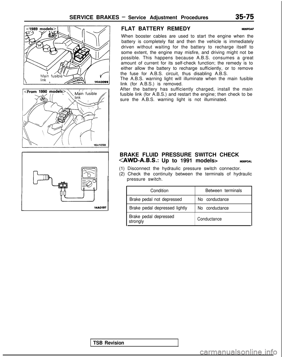
BRAKE FLUID PRESSURE SWITCH CHECK
(1) Disconnect the hydraulic pressure switch connector.
(2) Check the continuity between the terminals of hydraulic pressure switch.
Condition Between terminals
Brake pedal not depressed
No conductance
Brake pedal depressed lightlyNo conductance
Brake pedal depressed
stronglyConductance
Page 1262 of 1273
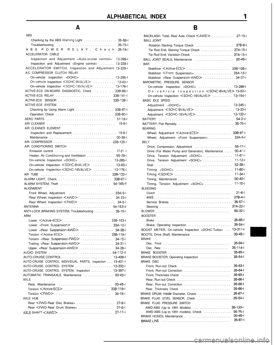
ALPHABETICAL INDEX1
A
ABS
Checking by the ABS Warnrng Light................
. 35-68-l
Troubleshooting ...........................
35-l 5-l
ABS POWER RELAY, Chec
k 35-74-l
ACCELERATOR CABLE
Inspection and Adjustment
13-398-l
Inspection and Adjustment
ACCELERATOR SWITCH, Inspection and Adjustment 13-329-I
A/C COMPRESSOR CLUTCH RELAY
On-vehicle Inspection
.............
. 13-285-l
On-vehrcle
Inspection
. 13-83-t
On-vehicle Inspection
. 13-176-l
ACTIVE-ECS ON-BOARD DIAGNOSTIC, Check......
. 338-88-I
ACTIVE-ECS RELAY.......................
. 338-141
-I
ACTIVE-ECS SENSOR....
.
...... ............ 338-138-I
ACTIVE-ECS SYSTEM
Checking by Using Alarm Light
.................
. 338-87-I
Operation Check ........................... 338-90-I
AERO PARTS..
.
........................... 51-18-l
AIR CLEANER...............................
. 15-9-I
AIR CLEANER ELEMENT
Inspection and Replacement
....................
. 15-6-l
Maintenance .......................... 00-39-l
AIR COMPRESSOR..........................
. 338-125-I
AIR CONDITIONING SWITCH
Emission control
...........................
.
17-21 -I
Heater, Air
Conditionrng
and Ventilation .............. 55-29-l
On-vehicle Inspection
On-vehicle Inspection
. 13-83-l
On-vehicle Inspection
. 13-176-l
AIR TUBE..............
.
....................... 338-133-I
ALARM LIGHT, Check. ......................... 338-87-I
ALARM SYSTEM, Theft ..........................
54-165-11
ALIGNMENT
Front Wheel, Adjustment .......................
. 33A-5-l
Rear
Wheel, inspection
. 34-23-l
Rear Wheel, Inspection
. 34-5-l
ANTENNA ......................................
54-153-11
ANTI-LOCK BRAKING SYSTEM, Troubleshooting .........
.
35-15-1
ARM
Lower
. 338-103-I
Lower
.
33A-10-I
Lower
................... 34-28-l
Torsion
.
338-l 19-l
Torsion
...................34-l 5-lTrailing
................. 34-31-l
Upper
.................. 34-28-l
AUDIO
SYSTEM................
.
.................
54-l 12-11
AUTO-CRUISE CONTROL. ..........................
. 13-408-I
AUTO-CRUISE CONTROL INDIVIDUAL PARTS, inspection..
. 13-401-I
AUTO-CRUISE CONTROL SYSTEM...................
. 13-332-l
AUTO-CRUISE CONTROL SYSTEM, Inspection..........
. 13-397-l
AUTOMATIC TRANSAXLE, Maintenance ................. 00-43-I
AXLE
Rear, Maintenance
...............................
. 00-45-I
Torsion
.
338-l 19-l
Torsion
.
......................... 34-15-l
AXLE HUB
Rear
Rear CFWD-Rear
Drum Brakes> ................... 27-6-l
AXLE SHAFT
.
27-17-1
B
BACKLASH. Total, Rear Axle, Check
. 27-15-l
BALL JOINT
Rotation Starting Torque Check ...................... 378-8-I
Tie Rod End, Staning Torque Check .................. 37A-15-l
Tie Rod End, Variation Check ....................... 37A-15-l
BALL JOINT SEALS, Maintenance ..................... 00-45-I
BAR
Stabilizer
. 338-106-I
Stabilizer
. 33A-13-l
Stabilizer
. 34-37-l
BAROMETRIC PRESSURE SENSOR
On-vehicle Inspection
................
. 13-266-l
On-vehicle Inspection
On-vehicle Inspection
. 13-154-l
BASIC IDLE SPEED
Adjustment
...........................
. 13-245-l
Adjustment
Adjustment
. 13-133-l
BATTERY.........................................
.
54-2-11
BATTERY, Flat Remedy.
.............................
. 35-75-l
BEARING
Wheel, Adjustment
. 338-87-I
Wheel, Adjustment
BELT
Drive, Compressor, Adjustment
....................
. 55-17-l
Drive (For Water Pump and Generator), Maintenance ..... 00-41-I
Drive, Tension Adjustment
Drive, Tension Adjustment
Seat..........................................
. 52-39-l
Timing
Timing
. 11-34-l
Timing, Maintenance ............................... 00-40-I
Timing, Tension Adjustment
BLEEDING
Clutch
..........................................
. 21-6-l
4ws...........................................
. 370-4-I
Service Brakes. .................................. 35-57-l
Steering ........................................ 37A-22-l
BLOWER..........................................
. 55-32-l
BOOSTER
Brake
.........................................
. 35-85-l
Brake, Operating Inspection ......................... 35-54-l
BOOST METER, On-vehicle Inspection
BOOTS, Drive Shaft, Maintenance ....................... 00-45-I
BRAKE
Disc, Front
......................................
. 35-94-l
Disc, Rear.....................................
.
35-l 14-l
BRAKE BOOSTER
...................................
. 35-85-l
BRAKE BOOSTER, Operating Inspection .................. 35-54-l
BRAKE DISC
Front, Run-out Check.
.............................
. 35-63-l
Front, Run-out Correction ........................... 35-64-l
Front, Thickness Check ............................. 35-65-l
Rear, Run-out Check ............................... 35-66-l
Rear, Run-out Correction. ........................... 35-66-l
Rear, Thickness Check............................
. 35-66-l
BRAKE DRUM, tnside
Diameter, Check ................... 35-67-l
BRAKE FLUID LEVEL SENSOR, Check...................
. 35-54-l
BRAKE FLUID PRESSURE SWITCH
AWD-ABS (Up to 1991 Models)
....................
.
35-133-l
AWD-ABS
(Up to 1991 models), Check ...............
. 35-75-l
BRAKE HOSES, Maintenance ........................... 06-45-t
BRAKELINE
........................................
35-87-l
Page 1263 of 1273
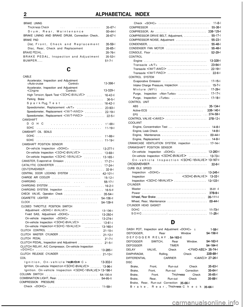
2ALPHABETICAL INDEX
BRAKE LINING ThicknessCheck
.., ..,............
Drum, Rear, Maintenanc
e
BRAKE LINING AND BRAKE DRUM, Connection Check..
BRAKE PAD
Drsc, Front, Check and Replacemen
t
Disc, Rear, Check and Replacement BRAKEPEDAL..
BRAKE PEDAL, Inspection and Adjustment
BUMPER..... 35-67-l
00-44-l
35-67-l
35-59-l
35-65-l
35-76-l
35-53-l
51-7-I
C
CABLEAccelerator, Inspection and Adjustment
Accelerator, Inspection and Adjustment
High
Tensron, Spark Test
.
16-42-11Parking Brake................................
.
36-5-l
Spark
Plug, Tes
t
........................
16-42-11Speedometer, Replacement ...............
.
23-93-l
Speedometer, Replacement
.
22-19-I
Speedometer, Replacement
.
22-5-l
CAMSHAFTDOH
C
...................
1 l-68-lSOHC.................................
.
11-19-I
CAMSHAFT OIL SEALS
DOHC
...................................
.
11-68-I
SOHC........................................
.
11-19-I
CAMSHAFT POSITION SENSOR
On-vehrcle Inspection
..................
.
13-277-l
On-vehicle Inspection
.
13-69-l
On-vehicle Inspection
.
13-165-I
CANISTER,
Evaporatjve Emission.................
.
17-21-l
CATALYTIC CONVERTER............................
.
17-24-l
CENTERMEMBER...................
.
....... 32-8-l
CENTRAL DOOR LOCKING SYSTEM..................
.
42-101-I
CHARGE AIR COOLER...............................
.
15-l
2-l
CHARGING..................
.
..... 55-17-I
CHARGING SYSTEM....................
.
...........
16-2-11CHARGING SYSTEM, Inspection.......................
.
16-5-11CHECK VALVE, Operation Check......................
.
35-54-l
CIGARETTE LIGHTER..........................
.
54-106-11
CLOCK........................................
.
54-109-11CLOSED THROTTLE POSITION SWITCHAdjustment
.................. 13-136-I
Frxed SAS, Adjustment
..................
.
13-250-I
On-vehicle inspection
On-vehicle Inspection
.
13-61-I
On-vehicle Inspection
. 13-160-I
CLUTCH CONTROL.................................
.
21-10-I
CLUTCH MASTER CYLINDER.........................
.
21-12-l
CLUTCH PEDAL.....................................
.
21-7-l
CLUTCH PEDAL, Inspection and Adjustment ................
21-5-1CLUTCH RELAY, A/C Compressor, On-vehicle Inspection
....................................... 13-285-l
CLUTCH RELEASE CYLINDER.........................
21-13-lCOIL
Ignition, On-vehicle
Inspectron
Ignition, On-vehicle
InspectIon
. 13-96-l
Ignition. On-vehicle Inspection
COLUMN SWITCH............................
.
54-100-11COMBINATION LIGHT, Rear.
.........................
.
54-95-11COMPRESSION PRESSURE
Check
...............................
.
1
i-59-1Check
..................................
11-8-l
COMPRESSOR...................................
.
55-38-l
COMPRESSOR, Air.......
.
........................ 338-125-I
COMPRESSOR DRIVE BELT, Adjustment, ................. 55-17-l
COMPRESSOR NOISE, Adjustment ...................... 55-23-l
CONDENSER, ............ .......................... 55-48-l
CONDENSER FAN MOTOR...........................
.
55-48-l
CONSOLE, Floor....................................
.
52-29-l
CONTROL
Engine
........................................
.
13-328-l
Transaxle ............................... 23-94-l
Transaxle
.
22-19-I
Transaxle
.
22-6-l
CONTROL SYSTEM
Evaporative Emission
.............................
.
17-15-l
Intake Charge Pressure, Inspection.
....................
15-7-lMixture (MFI
)
.............................. 17-29-l
Purge, Inspection
Purge, Inspection
CONTROL UNIT
ABS
........................................
.
35-134-l
Active-ECS ................................... 338-140-I
EPS.....................................
.
...37A-59-lCONTROL VALVE <4WS>..........................
.
378-12-I
COOLANT
Engine, Concentration Test ..........................
14-8-lEngine, Leak Check ................................
.
14-8-l
Engine, Maintenance. ............................ 00-44-I
Engine, Replacement ...........
................... 14-8-lCRANKCASE VENTILATION SYSTEM, inspection..........
.
17-14-l
CRANKSHAFT POSITION SENSOR
On-vehicle Inspection
..................
.
13-280-I
On-vehicle Inspection
.
13-73-l
On-vehicle Inspection
CROSSMEMBER....................................
.
32-8-l
CURB IDLE SPEED
Inspection
.......
.
.................... 13-245-l
Inspection
Inspection
.
13-133-l
CYLINDER
Master
.........................................
.
35-81 -IPower
.........................................
.
378-9-I
Wheel,RearBrake...............................
. 35-111-l
Wheel, Rear, Maintenance .......................... 00-44-I
CYLINDER HEAD GASKET
DOHC
.......................................
.
11-73-l
SOHC.................: ......................... 11-25-l
D
DASH POT, Inspection and Adjustment
1 l-58-lDEFOGGER, Rear Window 64-156-11
DEFOGGER RELA
Y
.54-163-11DEFOGGER SWITCH, Rear Window. 54-163-11
DEFOGGER TIMER 54-164-11
DELAY VALVE, Check
35-74-l
DIAPHRAGM, Rolling, Check 33B-89-l
DIFFERENTIAL CARRIER
DISC
Brake, Front, Run-out Check
35-63-l
Brake, Front, Run-out Correction 35-64-l
Brake, Front.
Thichness Check 35-65-l
Brake, Rear, Run-out Check 35-66-l
Brake, Rear, Run-out Correction 35-66-l
Brake, Rear,
Thichness Chec
k
35-66-l
Page 1265 of 1273
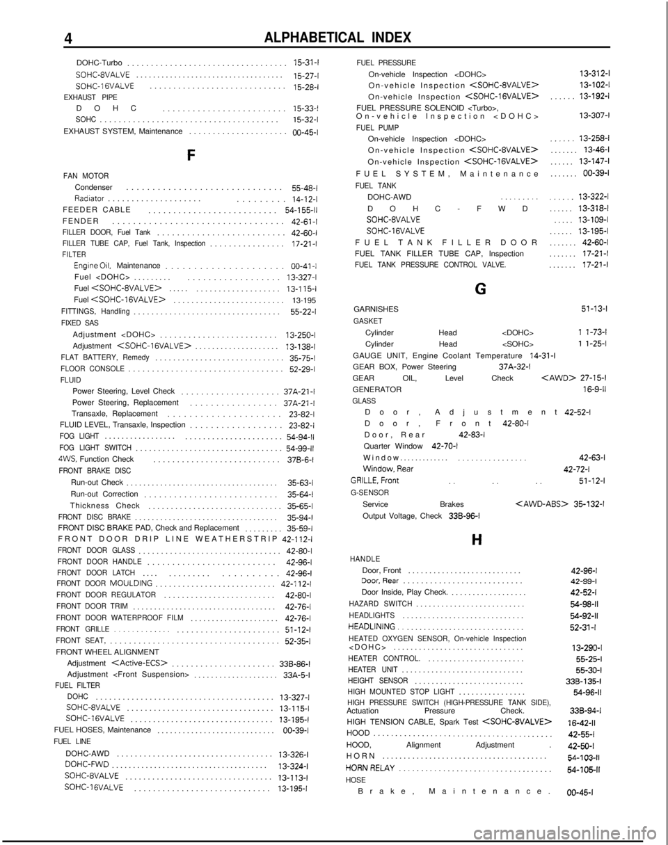
4ALPHABETICAL INDEX
DOHC-Turbo.................................
. 15-31-f
SOHC-8VALVE..................................
.
15-27-t
SOHC-1 GVALVE............................
.
15-28-l
EXHAUST PIPEDOH
C
......................... 15-33-I
SOHC.....................................
.
15-32-l
EXHAUST SYSTEM, Maintenance ..................... 00-45-I
F
FAN MOTOR
Condenser
.............................
.
55-48-l
Radiator...................
.
......... 14-12-I
FEEDER CABLE ..........................
54-l 55-11FENDER................................
.
42-61-t
FILLER DOOR, Fuel Tank.........................
.
42-60-I
FILLER TUBE CAP, Fuel Tank, Inspection...............
.
17-21 -I
FILTER
Engine 011. Maintenance ....................
. 00-41-I
Fuel
Fuel
.
...................
13-I 15-lFuel
.
13-195
FITTINGS, Handling................................
. 55-22-l
FIXED SAS
Adjustment
........................
.
13-250-I
Adjustment
.
13-138-I
FLAT BATTERY, Remedy............................
.
35-75-l
FLOOR CONSOLE................................
.
52-29-l
FLUID
Power Steering, Level Check
...................
. 37A-21-l
Power Steering, Replacement ................. 37A-21-l
Transaxle, Replacement ..................... 23-82-l
FLUID LEVEL, Transaxle, Inspection .................. 23-82-l
FOG LIGHT................
.
......................
54-94-11FOG LIGHT SWITCH................................
.
54-99-114WS, Function Check
..........................
. 37B-6-l
FRONT BRAKE DISC
Run-out Check
...................................
. 35-63-I
Run-out Correction ........................... 35-64-l
Thickness Check .............................. 35-65-l
FRONT DISC BRAKE.................................
. 35-94-l
FRONT DISC BRAKE PAD, Check and Replacement ......... 35-59-l
FRONT DOOR DRIP LINE WEATHERSTRIP 42-112-I
FRONT DOOR GLASS...............................
. 42-80-l
FRONT DOOR HANDLE.........................
. 42-96-l
FRONT DOOR LATCH...
.
......... .......... 42-96-l
FRONT DOOR
MOULDING
........................... 42-112-I
FRONT DOOR REGULATOR........................
. 42-80-I
FRONT DOOR TRIM.................................
. 42-76-l
FRONT DOOR WATERPROOF FILM....................
. 42-76-l
FRONT GRILLE..................................
. 51-12-l
FRONT SEAT,...................................
. 52-35-l
FRONT WHEEL ALIGNMENT Adjustment
. 338-86-I
Adjustment
FUEL FILTER
DOHC
.......................................
. 13-327-I
SOHC-8VALVE
.................................
13-l 15-l SOHC-IGVALVE
................................ 13-195-I
FUEL HOSES, Maintenance ............................
00-39-1
FUEL LINE
DOHC-AWD ..................................
.
13-326-l
DOHC-FWD....................................
.
13-324-l
SOHC-8VALVE
................................. 13-113-l
SOHC-1 ~VALVE............................
.
13-l 95-IFUEL PRESSURE
On-vehicle Inspection
On-vehicle Inspection
On-vehicle Inspection
FUEL PRESSURE SOLENOID
On-vehicle Inspection
FUEL PUMP
On-vehicle Inspection
On-vehicle Inspection
On-vehicle Inspection
FUEL SYSTEM, Maintenanc
e
FUEL TANK
DOHC-AWD .,.......
DOHC-FW
D
SOHC-8VALVE
SOHC-16VALVE
FUEL TANK FILLER DOO
R
FUEL TANK FILLER TUBE CAP, Inspection
FUEL TANK PRESSURE CONTROL VALVE. 13-312-l
13-102-I
,.....13-I
92-l
13-307-I
......
13-258-l
....... 13-46-l
...... 13-147-l
....... 00-39-l
......
13-322-l
...... 13-318-l
..... 13-109-I
...... 13-195-I
....... 42-60-I
....... 17-21-I
....... 17-21-l
G
GARNISHES
51-13-l
GASKET
Cylinder Head
Cylinder Head
GAUGE UNIT, Engine Coolant Temperature
14-31-l
GEAR BOX, Power Steering 37A-32-l
GEAR OIL, Level Check
GENERATOR
16-g-11
GLASS
Door, Adjustmen
t
42-52-l
Door, Front 42-80-I
Door, Rear 42-83-l
Quarter Window 42-70-I
Window.............
.._......_...... 42-63-i
Window,Rear
42-72-i
GRILLE,Front
_. _. _.
51-12-l
G-SENSOR
Service Brakes
35-132-l
Output Voltage, Check 336-96-l
H
HANDLE
Door, Front
..........................
.
Door,Rear
...........................
Door Inside, Play Check. ..................
HAZARD SWITCH.........................
.
HEADLIGHTS............................
.
HEADLINING.............................
.
HEATED OXYGEN SENSOR, On-vehicle Inspection
>
...............................
HEATER CONTROL.......................
.
HEATER UNIT............................
.
HEIGHT SENSOR.........................
.
HIGH MOUNTED STOP LIGHT...............
.
42-96-1 42-99-l
42-52-l
54-98-11
54-92-11
52-31-l
13-290-I
55-25-l
55-30-I
338-l
35-l
54-96-11HIGH PRESSURE SWITCH (HIGH-PRESSURE TANK SIDE),Actuation Pressure Check. 338-94-I
16-42-11
42-55-l
42-50-I
54-l 03-11
54-105-11
HIGH TENSION CABLE, Spark Test
HOOD .__...._..._......__._...................
HOOD, Alignment Adjustment .
HOR
N
. . . . . . . . . . . . . . . . . . . . . . . . . . . . . . . . . . . . \
. . . HORNRELAY
._.._._....___.........__.._._..___
HOSE
Brake, Maintenance
.
00-45-I