1989 MITSUBISHI GALANT check engine light
[x] Cancel search: check engine lightPage 1031 of 1273
33B-92 ACTIVE-ELECTRONIC CONTROL SUSPENSION - ~~:%:?stment
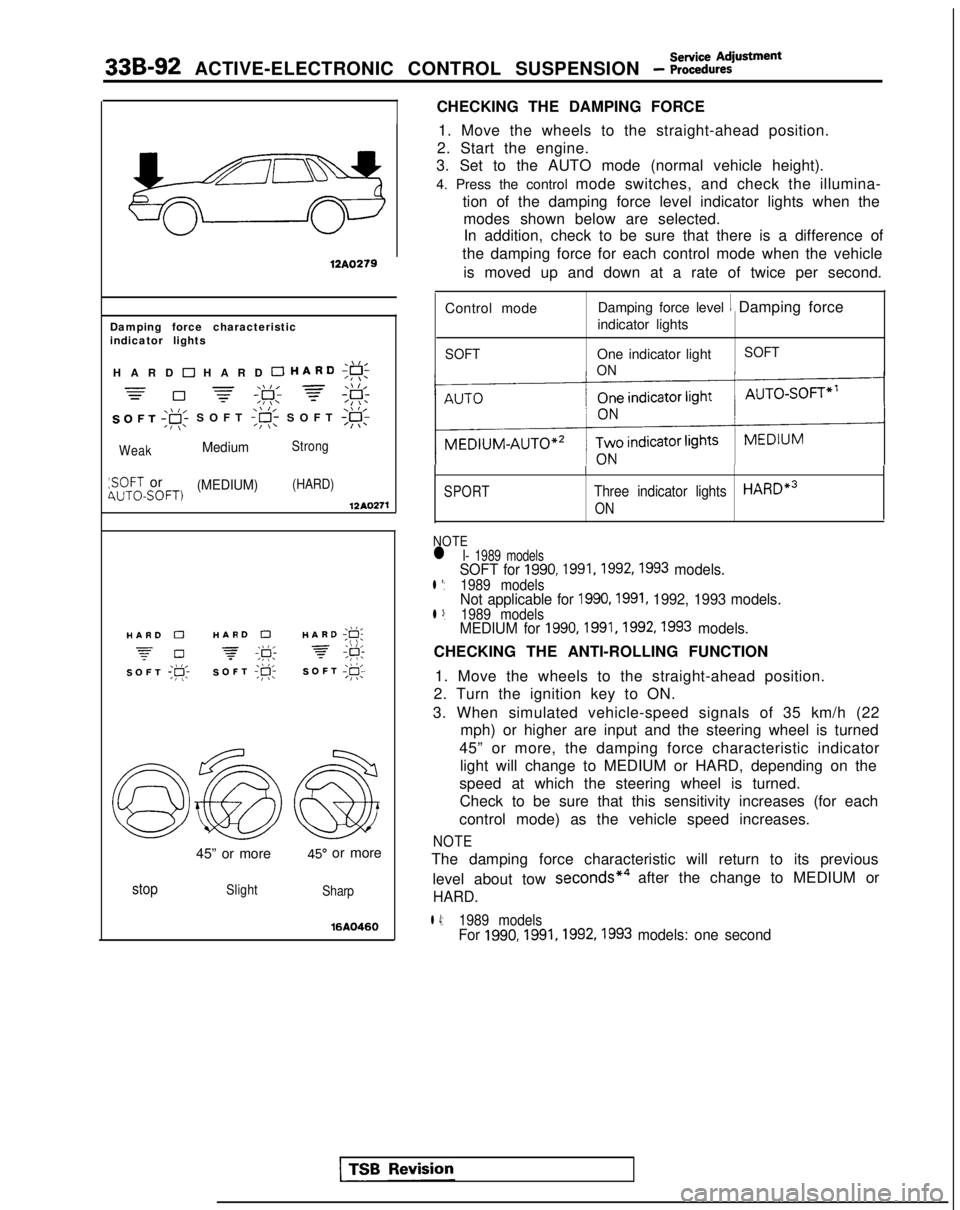
CHECKING THE DAMPING FORCE
12A0279
Damping force characteristic
indicator lights
,\,IHARD 0 HARD 0 HARD;g!;
=-\\I, =\\ l,=0 -=-,F; f;F:
SOFT ,gi SOFT
:SOFT or(MEDIUM)(HARD)4UTOSOFT)12AQ271
./I,HARD 0HARD 0HARD ;g;
z-0 -\k 3,\I I,SOFT ;p;SOFT ;R-SOFT I@;
45” or more45” or more
stopSlight
Sharp
16AQ460
1. Move the wheels to the straight-ahead position.
2. Start the engine.
3. Set to the AUTO mode (normal vehicle height).
4. Press the control mode switches, and check the illumina-
tion of the damping force level indicator lights when themodes shown below are selected.In addition, check to be sure that there is a difference of
the damping force for each control mode when the vehicle
is moved up and down at a rate of twice per second.
Control mode Damping force level
1 Damping force
indicator lights
SOFTOne indicator light
ON SOFT
SPORT
I
Three indicator lightsHARDe3
ON
NOTEl I- 1989 modelsSOFT for 1990,1991,1992,1993 models.l *:1989 modelsNot applicable for 1990,1991, 1992, 1993 models.l 3:1989 modelsMEDIUM for 1990,1991,1992,1993 models.
CHECKING THE ANTI-ROLLING FUNCTION
1. Move the wheels to the straight-ahead position.
2. Turn the ignition key to ON.
3. When simulated vehicle-speed signals of 35 km/h (22 mph) or higher are input and the steering wheel is turned
45” or more, the damping force characteristic indicator light will change to MEDIUM or HARD, depending on the
speed at which the steering wheel is turned. Check to be sure that this sensitivity increases (for each
control mode) as the vehicle speed increases.
NOTE
The damping force characteristic will return to its previous
level about tow seconds*4
after the change to MEDIUM or
HARD.
l 4:1989 modelsFor 1990,1991,1992,1993
models: one second
Page 1032 of 1273
Service AdjustmentACTIVE-ELECTRONIC CONTROL SUSPENSION - Procedures33B-93
\\ I/HARD ;g;
7 #
SOFT;#c
\\ I/HARD ;F;
7 ;&
SOFT;@;
I12AO399
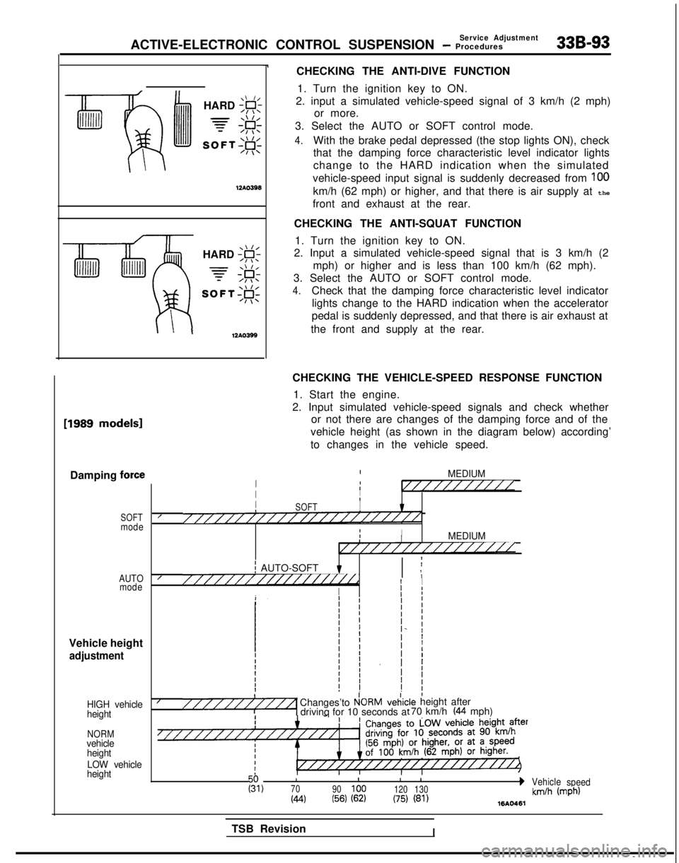
CHECKING THE ANTI-DIVE FUNCTION1. Turn the ignition key to ON.
2. input a simulated vehicle-speed signal of 3 km/h (2 mph) or more.
3. Select the AUTO or SOFT control mode.
4.With the brake pedal depressed (the stop lights ON), check
that the damping force characteristic level indicator lights
change to the HARD indication when the simulated
vehicle-speed input signal is suddenly decreased from
100
km/h (62 mph) or higher, and that there is air supply at the
front and exhaust at the rear.
CHECKING THE ANTI-SQUAT FUNCTION 1. Turn the ignition key to ON.
2. Input a simulated vehicle-speed signal that is 3 km/h (2
mph) or higher and is less than 100 km/h (62 mph).
3. Select the AUTO or SOFT control mode.
4.Check that the damping force characteristic level indicator lights change to the HARD indication when the accelerator
pedal is suddenly depressed, and that there is air exhaust at
the front and supply at the rear. [1989
models1
Damping force
SOFTmode
AUTO mode
Vehicle height
adjustment
HIGH vehicle
height
NORMvehicle
height
LOW vehicle
height
CHECKING THE VEHICLE-SPEED RESPONSE FUNCTION
1. Start the engine.
2. Input simulated vehicle-speed signals and check whether or not there are changes of the damping force and of the
vehicle height (as shown in the diagram below) according’
to changes in the vehicle speed.
IMEDIUMI1I//////////IIIII8SOFTI////////////////////////IIIIMEDIUMI////////////////
j AUTO-SOFT I ;I ,////////////////i//dI I
I
Ij I
I/Changes’to P!ORMveiic“““““1 drivinq for 10 seconds a:le height after t 70 km/h (44 mph)
III
I 1g,70
90100 120130bVehicle
speed
(44(56) (62)(75) (81)km/h (mph)1610461
TSB RevisionI
Page 1136 of 1273

SERVICE BRAKES - Anti-lock Braking System Troubleshooting35-15
ANTI-LOCK BRAKING SYSTEM
TROUBLESHOOTINGM35EElAE
PARTICULAR CHARACTERISTICS OF
THE ANTI-LOCK BRAKING SYSTEM
Models equipped with the anti-lock braking system
(A.B.S.) may exhibit one or more of the following
characteristics from time to time, but none of these
is abnormal.
(1)
(2)
A pulsing feeling in the brake pedal, or vibration
of the body or the steering wheel, when the
anti-lock braking system is activated by sudden
braking or by braking on a slippery road surface.
Actually, this phenomenon is an indication that
the anti-lock braking system is functioning nor-
mally.
When the vehicle speed reaches approximately
6 km/h (4 mph) after the engine is started and
the vehicle starts off (for the first time), awhining motor noise may be heard from the
engine compartment if the vehicle is traveling in
a quiet place. This noise is simply the result of a
self-check being made of the anti-lock braking
system operation.
TROUBLESHOOTING METHODS
Problems related to the anti-lock braking system
(A.B.S.) can be classified into two general categor-
ies: problems in the electrical system and those in
the hydraulic system. For problems in the electrical system, the on-board
diagnostic is built into the electronic control unit
(E.C.U.) causing the A.B.S. warning light to illuminate
as a warning to the driver. In this instance, checks
can be made by using the scan tool and oscillo-
scope.
Problems in the hydraulic system (poor braking,
etc.) can be located in the same way as for ordinary
brakes. There is, however, the necessity to check to
determine whether the problem is related to ordi-
nary brake components or to the components re-
lated to the A.B.S. To make this check, use the scan
tool.
HOW TO USE THE TROUBLESHOOTING
FLOW CHART
(1) Using the flow chart, check the ABS warning
light light-up sequence. Read the diagnostic
trouble codes and check the condition of bra-
king operation.
(2) Following the check chart listed in the remedy
column, perform the checks. There are [Expla- nation] and [Hint] in each check chart. Refer to
them when troubleshooting.
NOTE
ECU: Electronic control unit
HU:Hydraulic unit
TSB Revision
Page 1137 of 1273
35-16SERVICE BRAKES - Anti-lock Braking System Troubleshooting
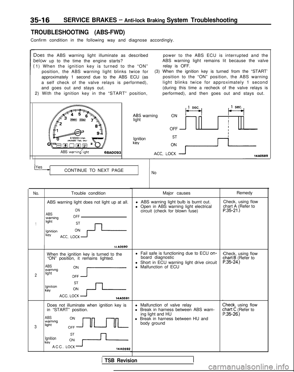
TROUBLESHOOTING (ABS-FWD)
Confirm condition in the following way and diagnose accordingly.
Ioes the ABS warning light illuminate as describedpower to the ABS ECU is interrupted and the
lelow up to the time the engine starts?ABS warning light remains lit because the valve
1) When the ignition key is turned to the “ON” relay is OFF.
position, the ABS warning light blinks twice for (3) When the ignition key is turned from the “START’
approximately 1 second due to the ABS ECU (as position to the “ON” position, the ABS warning
a self check of the valve relays is performed), light blinks twice for approximately 1 second
and goes out and stays out. (during this time a recheck of the valve relays is
2) With the ignition key in the “START” position, performed), and then goes out and stays out.
ABS warning
,,lseq (se+
lightII
OFF -I
Ignitionkey
ABS warnmg/;,ght68A009314A0589
YAS rICONTINUE TO NEXT PAGENo
No.
Trouble condition
ABS warning light does not light up at all.
ABSwarnina
ON
OFF
1light -
lgnltionkey
I14 A0590
When the ignition key is turned to the l Fail safe is functioning due to ECU on-
“ON” position, it remains lighted. board diagnostic
ABSwarning
2lightOZ7
l Short in ECU warning light drive circuit
l Malfunction of ECU
lgnitlonkev
ACC. LOi+14A0591
Does not illuminate when ignition key is
in “START” position.
ABSwarning
3light
Ignition
key ACC. LO:+14AO592
Major causes
l ABS warning light bulb is burnt out.
l Open in ABS warning light electrical circuit (check for blown fuse)
l Malfunction of valve relay
l Break in harness between ABS warn- ing light and HU
l Break in harness between HU and body ground Remedy
Check, using flow
chart A (Refer to
P.35-21.)
Check, using flowchart B (Refer toP.35-24.)
Check, using flow:hart C (Refer to ‘.35-26.)
1 TSB Revision
Page 1143 of 1273
35-22SERVICE BRAKES- Anti-lock Braking System Troubleshooting
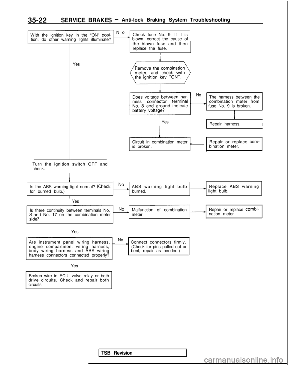
- N
o
With the ignition key in the “ON” posi-
Check fuse No. 9. If it is
tion. do other warning lights illuminate?
* blown, correct the cause of
the blown fuse and thenreplace the fuse.
I
Yes
Turn the ignition switch OFF and check.
4II., III,
Is the ABS warning light normal? (CheckNo cABS warning light bulb Replace ABS warning
for burned bulb.)burned.* light bulb.
I
Yes
NoThe harness between the
combination meter from
* fuse No. 9 is broken.
1
Repair harness.I
Circuit in combination metercRepair or replace com-
is broken. bination meter.
Yes
Is there continuity between terminals No.NoMalfunction of combination Repair or replace combi-
;,d”,l” No. 17 on the combination meter -meter
nation meter
Yes
Are instrument panel wiring harness, _
Noc Connect connectors firmly.
engine compartment wiring harness,
body wiring harness and ABS wiring
harness connectors connected properly? (Check for pins pulled out or
bent, repair as needed.)
Yes
Broken wire in ECU, valve relay or both
drive circuits. Check and repair both
circuits.
TSB Revision
Page 1145 of 1273
![MITSUBISHI GALANT 1989 Service Repair Manual 35-24
SERVICE BRAKES - Anti-lock Braking System Troubleshooting
B ABS warning light illuminated after the engine is started and remains o\
n.
[Explanation]
This is the symptom when the ABS ECU does no MITSUBISHI GALANT 1989 Service Repair Manual 35-24
SERVICE BRAKES - Anti-lock Braking System Troubleshooting
B ABS warning light illuminated after the engine is started and remains o\
n.
[Explanation]
This is the symptom when the ABS ECU does no](/manual-img/19/57312/w960_57312-1144.png)
35-24
SERVICE BRAKES - Anti-lock Braking System Troubleshooting
B ABS warning light illuminated after the engine is started and remains o\
n.
[Explanation]
This is the symptom when the ABS ECU does not
power up due to broken ECU power circuit, etc.,
when the fail safe function operates and isolates the
system or when the warning light drive circuit is
short circuited.
[Hint]
Check the on-board diagnostic output and if there is
no output voltage or if the scan tool and ABS ECU
cannot communicate, there is a good possibilit
y
that power is not flowing to the ECU.
Caution
l If there is no output of diagnostic trouble
codes, there is a good possibility that the
fail safe is functioning.
J/B
IGNITION
%FH
z
&7
i
CD10A
728
Is there on-board diagnostic No )output? (Is there communi-cation with scan tool?) CONTINUE TONEXT PAGE
Yes
TSB Revision
Does the ABS warning light
remain illuminated
even
with the ECU connector dis-
connected?
YesNoShort in ECU transistor
1 Replace ECU.I
Page 1155 of 1273
35-34SERVICE BRAKES - Anti-lock Braking System Troubleshooting
TROUBLESHOOTING (ABS-AWD)
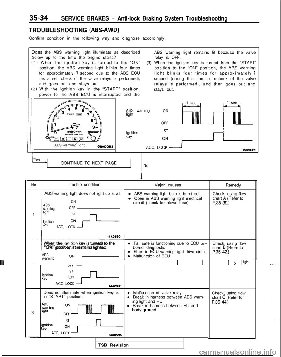
Confirm condition in the following way and diagnose accordingly.
c
P
t:
1
-)oes
the ABS warning light illuminate as described
elow up to the time the engine starts?
1) When the ignition key is turned to the “ON”
position, the ABS warning light blinks four times
for approximately
1 second due to the ABS ECU
(as a self check of the valve relays is performed),
and goes out and stays out.
2) W
ith the ignition key in the “START” position,
power to the ABS ECU is interrupted and the ABS warning light remains lit because the valve
relay is OFF.
(3) When the ignition key is turned from the “START’ position to the “ON” position, the ABS warning
light blinks four times for approximately
1
second (during this time a recheck of the valve
relays is performed), and then goes out and
stays out.
,,,\~~\l’l”“F’,r//,,,l/,,
a+’4 4 5r’o, (j /z$$+3,,,,%&73,
:
f=&L-gy
82
1cJz
x 1000
rimonUILEAED nxL GNL”Oyg@O@~ 2F
ABS
warnmg’l~ght66A0093
ABS warning
lightONI
OFF
Ignitionkey
ACC, LOCK
114AO594
YesCONTINUE TO NEXT PAGENo
1
No.Trouble condition
ABS warning light does not light up at all.
1
ABSwarning
light
Ignition
keyACC, ON
OFFLOCK 1
I
When the lgnltlon
key IS turned to the
“ON” position, it remains lighted.
ABS warnina
ON , l Short in ECU warning light drive circuit
l Malfunction of ECU
-“l-l- -III
ignitionkey
ACC. LO!?-14AO591
Major causes
l ABS warning light bulb is burnt out.
l Open in ABS warning light electrical circuit (check for blown fuse)
l Fail safe is functioning due to ECU on-
board diagnostic
Does not illuminate when ignition key is
in “START” position. l Malfunction of valve relay
l Break in harness between ABS warn-
ing light and HU
l Break in harness between HU and
14AO595
Remedy
Check, using flow
chart A (Refer to
P.35-39.)
Check, using flow
chart B (Refer toP.35-42.)
1 2 /light
-
Check, using flow
chart C (Refer to
P.35-44.)
TSB Revision
Page 1161 of 1273
SERVICE BRAKES - Anti-lock Braking System Troubleshooting
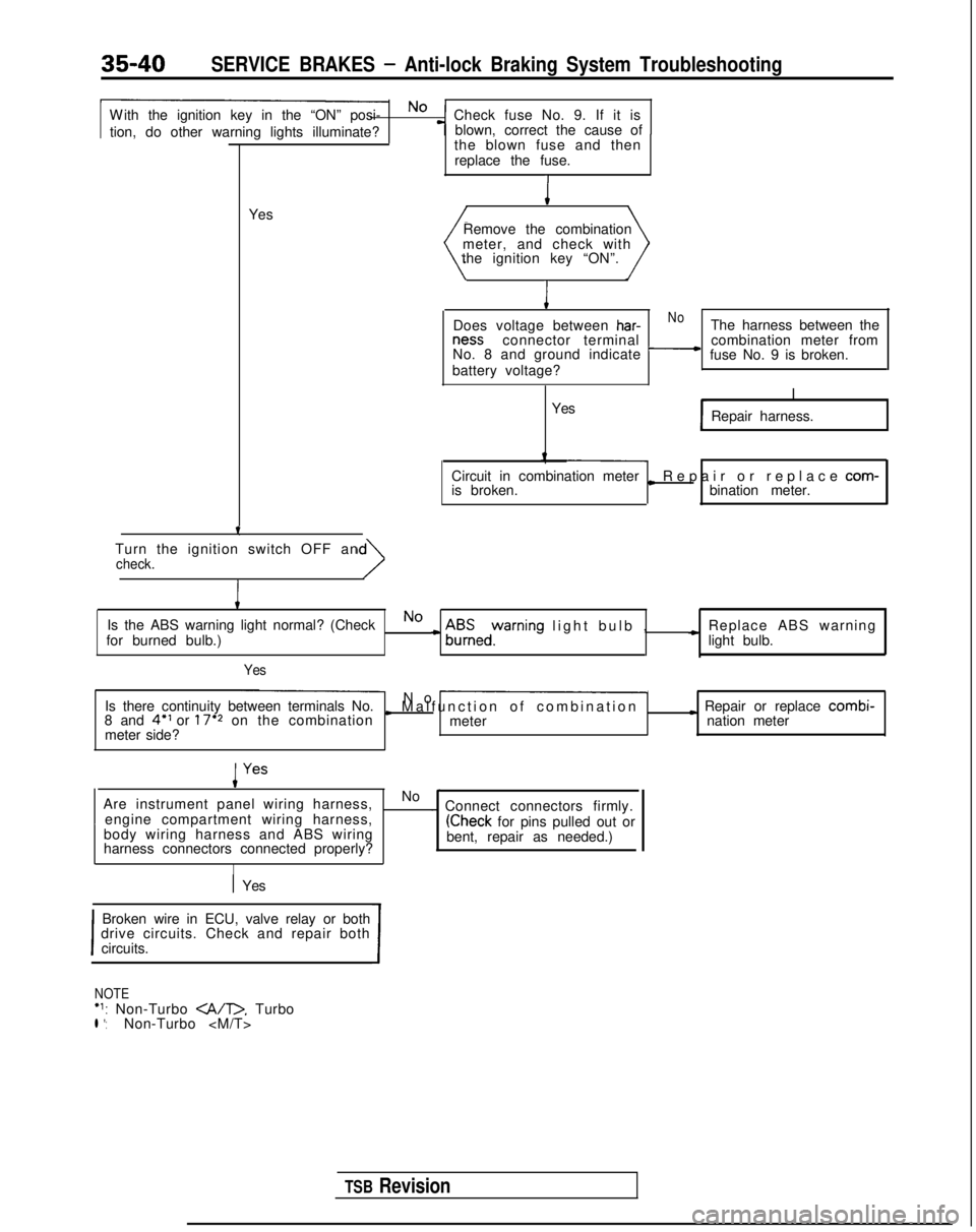
W
ith the ignition key in the “ON” posi- No
Check fuse No. 9. If it is
tion, do other warning lights illuminate? blown, correct the cause of
-T-
Yesthe blown fuse and then
replace the fuse.I
Remove the combination
meter, and check with
the ignition key “ON”.
I
Does voltage between har-NoThe harness between the ness
connector terminal
No. 8 and ground indicate
-combination meter from
fuse No. 9 is broken.
battery voltage?
I
Yes Repair harness.
Circuit in combination meter
is broken.
L Repair or replace com-
bination meter.
Turn the ignition switch OFF an
check.
I
Is the ABS warning light normal? (CheckNo
for burned bulb.)c A$Eedyrning light bulb
,
c Replace ABS warning
light bulb.
Yes
Is there continuity between terminals No. No -
8 and 4” or 17’2 on the combinationI Malfunction of combinatio
n
meter
I Repair or replace combi-
meter side? nation meter
Are instrument panel wiring harness, No
-~
engine compartment wiring harness, . Connect connectors firmly.
body wiring harness and ABS wiring
(Check for pins pulled out or
harness connectors connected properly? bent, repair as needed.)
I
1 Yes
I
Broken wire in ECU, valve relay or both
drive circuits. Check and repair both
circuits.
I
NOTE‘1: Non-Turbo . Turbol *:Non-Turbo
TSB Revision