1989 MITSUBISHI GALANT check engine light
[x] Cancel search: check engine lightPage 233 of 1273
FUEL SYSTEM
Inspection of MFI Components13-91
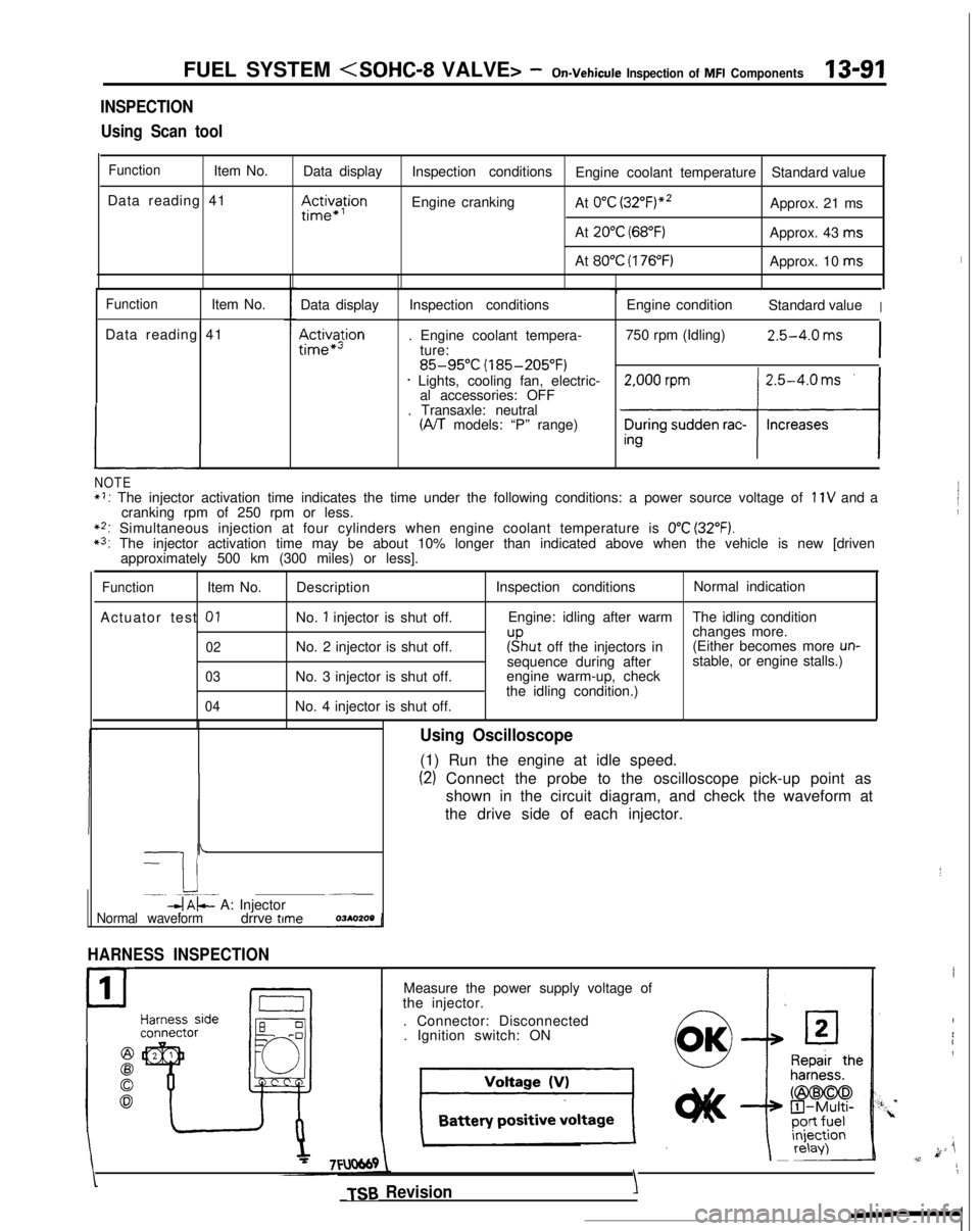
INSPECTION
Using Scan tool
FunctionItem No. Data display
Data reading 41
III~~~ion
Inspection conditions Engine coolant temperature Standard value
Engine cranking At
0°C (3~2°F)“~Approx. 21 ms
At
20°C (68°F)Approx. 43 ms
At
80°C (176°F)Approx. 10 ms
FunctionItem No.
Data reading 41
L
Data display
Ac&a$ion
Inspection conditions
. Engine coolant tempera- ture:
85-95°C (185-205°F)* Lights, cooling fan, electric-al accessories: OFF
. Transaxle: neutral
(A/T models: “P” range) Engine condition
Standard value
I
750 rpm (Idling)2.5-4.0 ms
I
NOTE*I: The injector activation time indicates the time under the following con\
ditions: a power source voltage of 11V and a
cranking rpm of 250 rpm or less.
**: Simultaneous injection at four cylinders when engine coolant temperatur\
e is 0°C (32°F).*3: The injector activation time may be about 10% longer than indicated abo\
ve when the vehicle is new [driven approximately 500 km (300 miles) or less].
FunctionItem No.
Actuator test
01
02
03
04
Description
No.
1 injector is shut off.
No. 2 injector is shut off.
No. 3 injector is shut off.
No. 4 injector is shut off. Inspection conditions
Normal indication
Engine: idling after warm The idling condition
changes more.
r”sput off the injectors in(Either becomes more un-sequence during after stable, or engine stalls.)
engine warm-up, check
the idling condition.)
-
I i-. --.-~-db$- A: Injector~__
Normal waveformdrrve time
HARNESS INSPECTION
1
P
Using Oscilloscope
(1) Run the engine at idle speed.
(2) Connect the probe to the oscilloscope pick-up point as
shown in the circuit diagram, and check the waveform at
the drive side of each injector.
Measure the power supply voltage of
the injector.
. Connector: Disconnected. Ignition switch: ON
TSB Revision
I
I
4
i1
k ji,v,11
\
YIY’.
Page 238 of 1273
13-96 FUEL SYSTEM
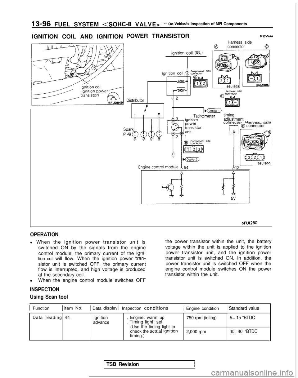
IGNITION COIL AND IGNITION POWER TRANSISTOR
ignition coil (IGI)
Ml3WAA
Harness side
@connector0
Harness side
Component side
Distributor\/ 2
4.I_lgnltion. .!
I@LZ)
TachcImetertimingA? I--:*:^^adjustment-_
Lllrnacr
r;rlnI 101 i IG.72 Jl”F
Componenr side
6FU1280
OPERATION
l When the ignition power transistor unit is
switched ON by the signals from the engine
control module, the primary current of the igni-
tion coil will flow. When the ignition power tran-
sistor unit is switched OFF, the primary current
flow is interrupted, and high voltage is produced
at the secondary coil.
l When the engine control module switches OFF
INSPECTION
the power transistor within the unit, the battery
voltage within the unit is applied to the ignition
power transistor unit, and the ignition power
transistor unit is switched ON. In addition, the power transistor unit is switched OFF when the
engine control module switches ON the power
transistor within the unit.
Using Scan tool
1 Function1 Item No.1 Data display / Inspection conditions/ Engine condition 1 Standard value
Data reading 44
Ignition
advance . Engine: warm up
750 rpm (idling)5- 15 “BTDC. Timing light: set(Use the timing light to
check the actual ignition
2,000 rpm 30-40 “BTDCtiming.)
1 TSB Revision
Page 248 of 1273
13-106
FUEL SYSTEM
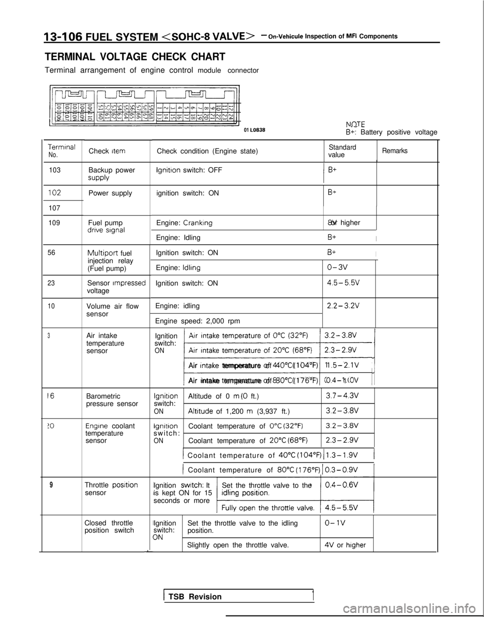
TERMINAL VOLTAGE CHECK CHART
Terminal arrangement of engine control module connector NflTF
01 LO838
. .- -B+: Battery positive voltage
Terminal
No.Check condition (Engine state)StandardvalueRemarksCheck item
103
Backup power supply lgnitron
switch: OFF
102Power supply ignition switch: ONB+
107
109
Fuel pump dnve signal
Engine: Cranking 8V or higher
Engine: Idling
B+I
Ignition switch: ON
Engine:
ldlrng
Ignition switch: ON
Engine: idling
Engine speed: 2,000 rpm
B+I
o-3v
4.5- 5.5v
2.2- 3.2V
56
23
10
Multiport fuel
injection relay
(Fuel pump)
Sensor
rmpressecvoltage
Volume air flow
sensor
Air intake
temperature sensor Ignition
Air intake temperature of
0°C (32°F)switch:ONAir Intake temperature of 20°C (68°F); ji/
Air Intake temperature of 40°C (104°F)1.5-2.1V
Air intake temperature of 80°C (176’F)0.4- 1 .OV
Barometric
pressure sensor
Ignition
Altitude of 0 m (0 ft.)3.7-4.3vswitch:ON Altitude
of 1,200 m (3,937 ft.)3.2-3.av
Engrne coolant lgnitron
Coolant temperature of 0°C (32°F)3.2-3.Wtemperature switch: -sensorONCoolant temperature of 20°C (68°F)2.3-2.9v
1 Coolant temperature of 40°C
(104°F) 1 1.3- 1.9V(
) Coolant temperature of 80°C
(176’F)
1 0.3-0.9V
Throttle posrtionsensor Ignition swatch: It
Set the throttle valve to the
is kept ON for 15
seconds or more
Closed throttle position switchII
I
I
-
Ignition Set the throttle valve to the idlingo-1vswitch:position.3NSlightly open the throttle valve. 4V
or higher
3
16
!O
9
1 TSB Revision1
Page 249 of 1273
FUEL SYSTEM
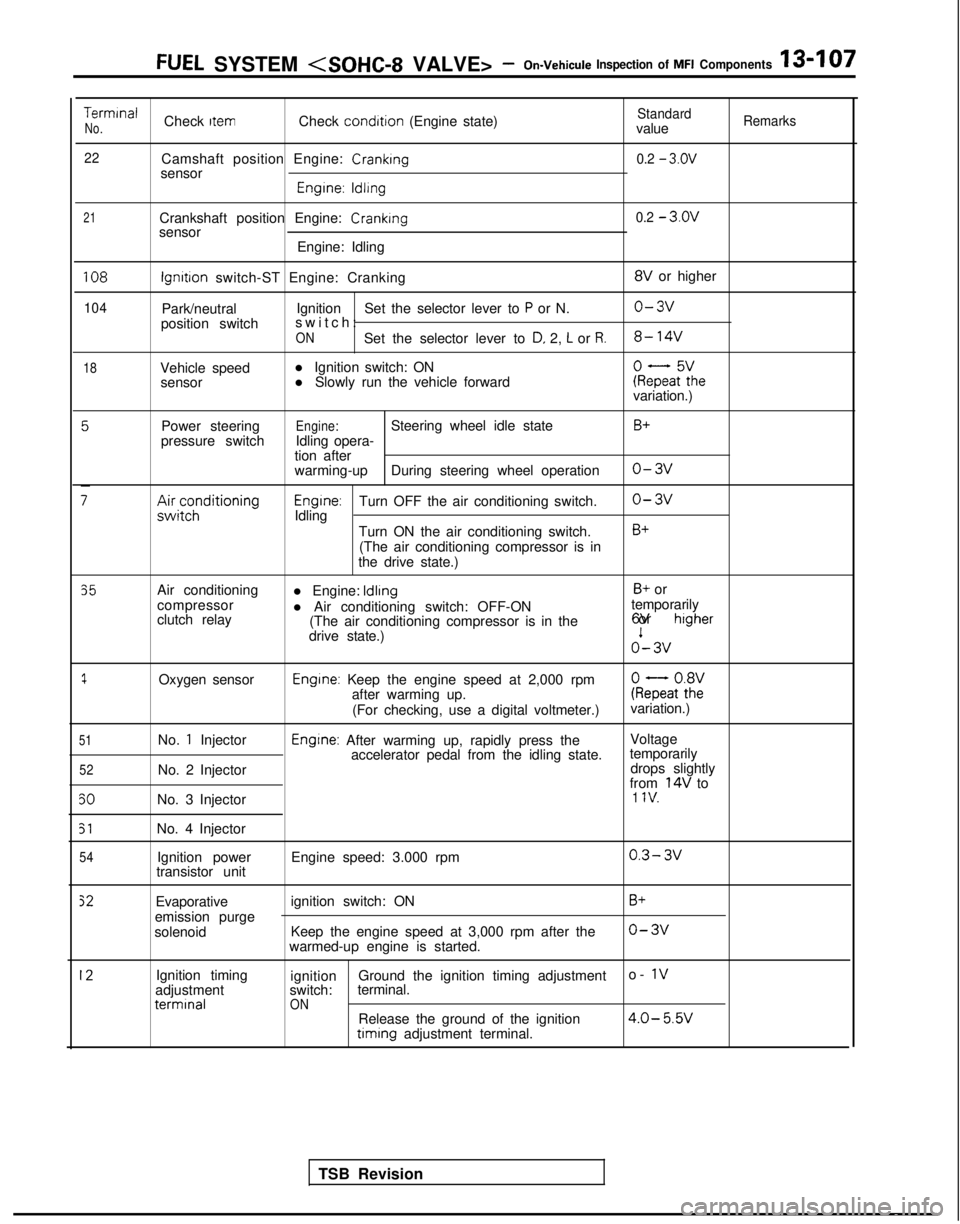
TerminalCheck ItemCheck condition
(Engine state)StandardNo.valueRemarks
22
Camshaft position Engine: Cranking0.2 - 3.ov
sensor
Engrne: ldllng
21Crankshaft position Engine: Crankingsensor
Engine: Idling0.2 - 3.ov
108
104
18
lgnrtron switch-ST Engine: Cranking 8V
or higher
Park/neutral Ignition
Set the selector lever to
P or N.o-3v
position switch switch
:
ONSet the selector lever to D, 2, L or R.8- 14V
Vehicle speed
l Ignition switch: ON
sensor l Slowly run the vehicle forwardkeFaF:hevariation.)
Power steering
pressure switch
;;ir;z;ditioning
Engine:Steering wheel idle state
Idling opera-
tion after
warming-up During steering wheel operation
Engrne:Turn OFF the air conditioning switch.
Idling
Turn ON the air conditioning switch.(The air conditioning compressor is in
the drive state.)
B+
o-3v
o-3v
B+
35
1
51
52
50
51
54
Air conditioning
compressor
clutch relay
Oxygen sensor
No.
1 Injector
No. 2 Injector
No. 3 Injector
No. 4 Injector Ignition power
transistor unit l Engine: Idling
B+ or
l Air conditioning switch: OFF-ON temporarily
(The air conditioning compressor is in the 6V or
higher
drive state.)o’- 3v
Engine: Keep the engine speed at 2,000 rpm
after warming up. kQatot8h2:
(For checking, use a digital voltmeter.) variation.)
Engine: After warming up, rapidly press the
Voltage
accelerator pedal from the idling state. temporarily
drops slightly
from
14V to1 IV.
Engine speed: 3.000 rpm0.3- 3v
Evaporative
emission purge
solenoid ignition switch: ON
Keep the engine speed at 3,000 rpm after the
warmed-up engine is started.B+
o-3v
12Ignition timing
adjustment terminal
ignition
Ground the ignition timing adjustment o- 1vswitch:
terminal.ONRelease the ground of the ignition4.0- 5.W timing
adjustment terminal.
TSB Revision
Page 250 of 1273
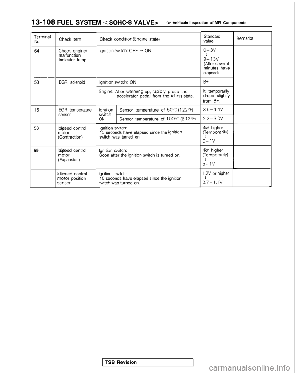
13-108 FUEL SYSTEM
TermrnalNo.
64
__-
53
15
58
59
Check Item
Check engine/
malfunction
Indicator lamp
EGR solenoid
EGR temperature
sensor Idle speed control
motor
(Contraction) Idle speed control
motor
(Expansion)
II
dle speed controlrnotor positions
;ensor
Check
condrtron (Engrne state)
lgnrtron swatch: OFF - ON
lgnrtron swatch: ON
Engine: After warming
up, raprdly press the
accelerator pedal from the rdlrng state.
lgnrtronSensor temperature of 50°C (122°F)swrtch,ONSensor temperature of 100°C (2 12°F)
Ignition swatch:15 seconds have elapsed since the IgnitlOnswitch was turned on.
Ignition switch:Soon after the ignitron switch is turned on.
gnition switch:15 seconds have elapsed since the ignitionswitch was turned on.
Standardvalue
o-3v
9’- 13v(After several
minutes have
elapsed)
B+
It temporarily
drops slightly
from
B+.
3.6-4.4v
2.2- 3.OV 4V or higher
(:emporarily)
o-1v
4V or higher
(:emporarily)
o-
IV
1.2V or higher
A- 1.1v
qemarks
TSB Revision
Page 262 of 1273
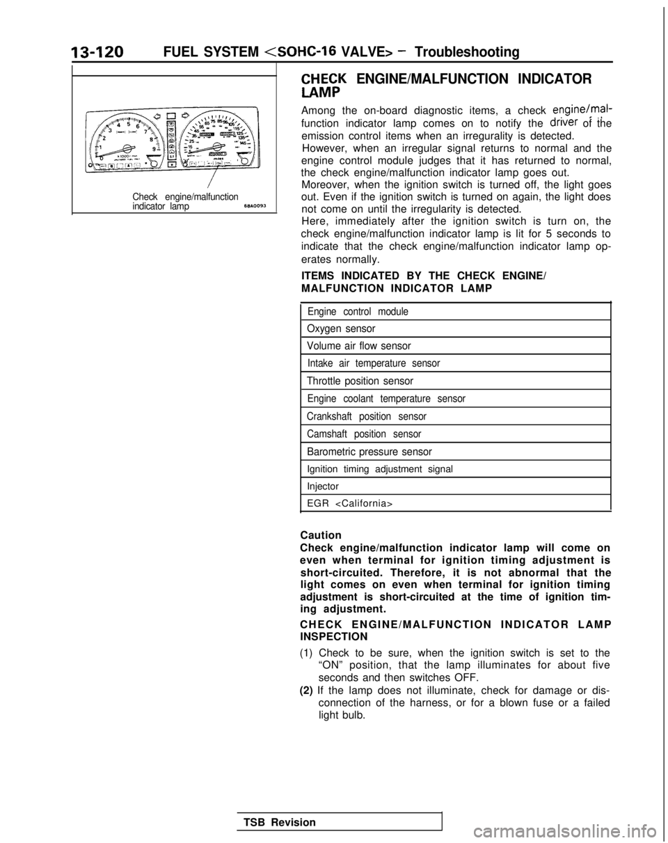
13-120FUEL SYSTEM
CHH;K
ENGINE/MALFUNCTION INDICATOR
Among the on-board diagnostic items, a check engine/mal-
function indicator lamp comes on to notify the driver
of the
emission control items when an irregurality is detected. However, when an irregular signal returns to normal and the
engine control module judges that it has returned to normal,
the check engine/malfunction indicator lamp goes out. Moreover, when the ignition switch is turned off, the light goes
Check engine/malfunctionout. Even if the ignition switch is turned on again, the light doesindicator lamp68A.0093not come on until the irregularity is detected.
Here, immediately after the ignition switch is turn on, the
check engine/malfunction indicator lamp is lit for 5 seconds to indicate that the check engine/malfunction indicator lamp op-
erates normally.
ITEMS INDICATED BY THE CHECK ENGINE/
MALFUNCTION INDICATOR LAMP
Engine control module
Oxygen sensor
Volume air flow sensor
Intake air temperature sensor
Throttle position sensor
Engine coolant temperature sensor
Crankshaft position sensor Camshaft position sensor
Barometric pressure sensor
Ignition timing adjustment signal
Injector
EGR
Caution
Check engine/malfunction indicator lamp will come on
even when terminal for ignition timing adjustment is short-circuited. Therefore, it is not abnormal that the
light comes on even when terminal for ignition timing
adjustment is short-circuited at the time of ignition tim-
ing adjustment.
CHECK ENGINE/MALFUNCTION INDICATOR LAM
P
INSPECTION
(1) Check to be sure, when the ignition switch is set to the “ON” position, that the lamp illuminates for about five
seconds and then switches OFF.
(2) If the lamp does not illuminate, check for damage or dis- connection of the harness, or for a blown fuse or a failedlight bulb.
TSB Revision
Page 275 of 1273

FUEL SYSTEM
FUEL TANK AND FUEL LINEMIBEAAB
Symptom
Probable cause Remedy
Engine malfunctions
due to insufficient
fuel supply Bent or kinked fuel pipe or hose
Clogged fuel pipe or hose
Clogged fuel filter or in-tank fuel filter
Water in fuel filter Repair or replace
Clean or replace
Replace
Replace the fuel filter or clean the
fuel tank and fuel line
Dirty or rusted fuel tank interior
Clean or replace
Malfunctioning fuel pump
(Clogged filter in the pump)Replace
Evaporative emission
control system
malfunctions
[When fuel tank filler
tube cap is removed,
pressure releasingnoise is heard) Mispiping of vapor line
Disconnected vapor line piping joint
Folded, bent, cracked or clogged vapor line
Faulty fuel tank filler tube cap
Malfunctioning fuel tank pressure control valve Correct
Correct
Replace
Replace
Replace
SERVICE ADJUSTMENT
PROCEDURES
CURB IDLE SPEED INSPECTIONhll3MAE
(1) The vehicle should be prepared as follows before th
e
inspection.
lEngine coolant temperature: 85-95°C (185-203°F)
l Lights, electric cooling fan and accessories: OFF
l Transaxle: Neutral (P for vehicles with an automatic
transaxle)
(2) Connect a tachometer.
NOTE
Refer to
P.13-134 for information concerning connection Of
a tachometer.
(3) Set a timing light in position.
(4) Ground the terminal for adjustment of ignition timing.
(5) Start the engine and let it idle.
(6) Check whether or not the ignition timing is the standard
value; if not, adjust.
Standard value:
5”BTDC f 2”
(7) Stop grounding the terminal for adjustment of ignition timing.
(8) Let the engine idle for two minutes.
(9) Check the idling rpm.
Curb idle speed: 700
31100 rpm
NOTE
The idling rpm is automatically regulated by the idle aircontrol system.
(lO)lf not within the standard value range, refer to the CHECK
CHART CLASSIFIED BY PROBLEM SYMPTOMS and check
the
MFI component,
TS6 Revision1
Page 305 of 1273
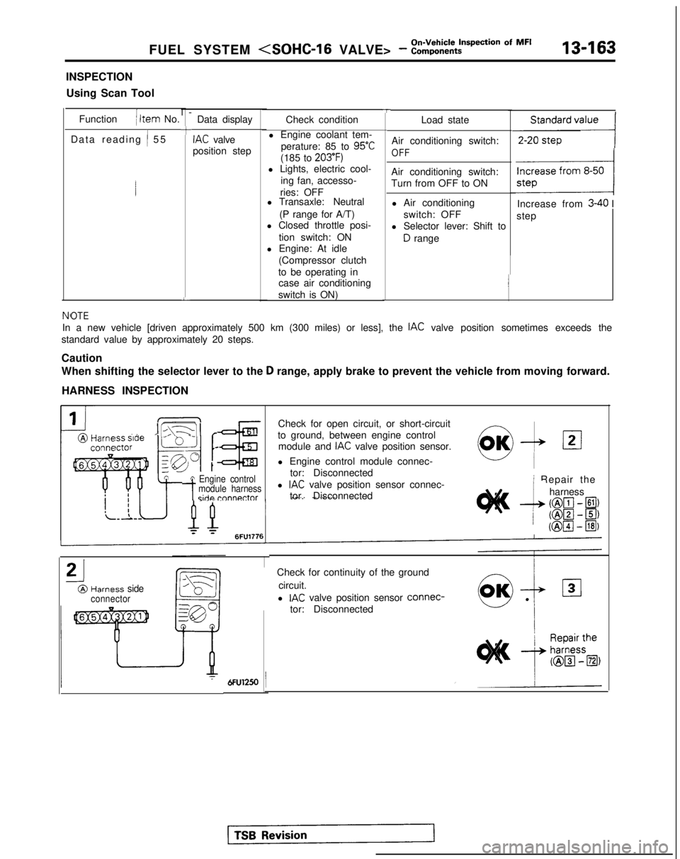
FUEL SYSTEM
INSPECTION
Using Scan Tool
Function
( Item No.
Data reading
/ 5
5
l-
+
L
Data display
IAC valve
position step
TCheck condition
l Engine coolant tem- perature: 85 to
95°C
(185 to 203’F)l Lights, electric cool- ing fan, accesso-
ries: OFF
l Transaxle: Neutral
(P range for A/T)
l Closed throttle posi-
tion switch: ON
l Engine: At idle
(Compressor clutch
to be operating in case air conditioning
switch is ON) Load state
Air conditioning switch:
OFF
Air conditioning switch:
Turn from OFF to ON l Air conditioning switch: OFF
l Selector lever: Shift to
D range
,,,,,,,,,I
Increase from 3-40 I
step
NfOTE
In a new vehicle [driven approximately 500 km (300 miles) or less], th\
e IAC valve position sometimes exceeds the
standard value by approximately 20 steps.
Caution
When shifting the selector lever to the
D range, apply brake to prevent the vehicle from moving forward.
HARNESS INSPECTION
IIL\-11 r@Harm ” ’ -conna
tA Engine control
-tmodule harnessside rnnnnctor
Check for open circuit, or short-circuit
to ground, between engine control module and
IAC valve position sensor.
l Engine control module connec- tor: Disconnected
l
IAC valve position sensor connec-
tor. Disconnected
21
@Harness sideconnector
0,OK-& 121
i Repair the
--L
harness
(@lcl- El)
/ ml-~) (@pJ
- @I)
Check for continuity of the ground
circuit.
l
IAC valve position sensor connec-
tor: Disconnected