1988 PONTIAC FIERO battery replacement
[x] Cancel search: battery replacementPage 879 of 1825
6E3-C1-4 5.0L (VIN F) & 5.7L(VIN 8) DRIVEABILITY AND EMISSIONS
See Section "8A" for more information on the PIN
switch, which is part of the neutrallstart and backup
light switch assembly.
NC "ON" Signal
This signal tells the ECM that the NC selector
switch is turned "ON", and that the pressure cycling
switch is closed. The
ECM uses this to adjust the idle
speed when the air conditioning is working.
[f this signal is not available to the ECM, idle may
be rough, especially when the NC compressor cycles.
The voltage at ECM terminal "B8" should equal
battery voltage on a
C60 system and about 5 volts on a
C68 option, when
NC is requested and the pressure
cycling switch is closed.
Distributor Reference Signal
The distributor sends a signal to the ECM to tell it
both engine rpm and crankshaft position. See ignition
system Section
"C4" for further information.
DIAGNOSIS
To read the codes, use a "Scan" tool or ground the
diagnostic terminal with the engine not running and
the ignition "ON". The "Service Engine Soon" light
will flash Code 12 three times and then flash each code
stored in memory three times. All codes stored in
memory would have been read when Code 12 was
flashed again. No new codes can be stored when in the
diagnostics mode (diagnostics lead grounded). This
eliminates confusion while the system is being worked
on.
To clear the codes from memory:
@ Ignition "OFF".
@ Disconnect battery pigtail, located near the
battery, for 30 seconds.
Since the ECM can have a failure which may
affect only one circuit, following the diagnostic
procedures in this section will determine which circuit
has a problem and where it is.
If a diagnostic chart indicates that the
ECM
connections or ECM is the cause of a problem,and the
ECM is replaced, but does not correct the problem, one
of the following may be the reason:
-
@ There is a problem with the ECM terminal
connections.
- The diagnostic chart will say ECM
connections or ECM. The terminals may have to
be removed from the connector in order to check
them properly.
@ The ECM, or Mem-Cal is not correct for the
application.
- The incorrect components may cause
a malfunction and
may or may not set u code.
@ The problem is intermittent. - 'l'his means that the
problem is not present at the time the system is
being checked. In
this case, refer to the "Symptoms" portion
of the
manual and make a careful physical inspection
of
all portions of the system involved.
@ Shorted solenoid, relay coil, or harness. - Solenoids
and relays are turned
"ON" and "OFF" by the
ECM, using internal electronic switches called
"Drivers".
A shorted solenoid, relay coil, or harness in a
GMP4 computer will not damage the ECM,
but will cause the circuit and controlled
component to be inoperative. When the
circuit fault is not present or has been
repaired, the
"Quad-Driver" will again
operate in a normal manner due to it's fault
protected design.
If a fault has been repaired
in a circuit controlled by a "Quad-Driver",
the original ECM should be reinstalled and
the circuit checked for proper operation.
ECM replacement will
not be necessary if the
repaired circuit or component now operates
correctly.
534636 or BT 8405 testers or equivalent provide a
fast, accurate means of checking for a shorted coil
or a short to battery voltage.
@ The Mem-Cal may be faulty. - Although these
rarely fail, it operates as part of the ECM.
Therefore, it could be the cause
of the problem.
Substitute a known good Mem-Cal.
@ The replacement ECM may be faulty - After the
ECM is replaced, the system should be rechecked
for proper operation. If the diagnostic chart again
indicates the ECM is the problem, substitute a
known good ECM. Although this is a rare
condition, it could happen.
ECM
A faulty ECM will be determined in the diagnostic
charts.
MEM-CAL
An incorrect or faulty Mem-Cal, which is part of
the ECM, may set a Code 41 or 52. Also, be sure Mem-
Cal is fully seated and latched in the socket.
ECM INPUTS
A11 of the sensors and input switches can be
diagnosed by the use of
a "Scan" tool. Following is a
short clescription of how the sensors and switches can
he diagnosed
by the use of a "Scan" tool. The "Scan"
can also be used to compare the values for a normal
running engine with the engine you're diagnosing.
Page 881 of 1825
6E3-C9-6 5.OL (VIN F) & 5.7L (VIN 8) DRIVEABILIW AND EMISSIONS
INSTRUMENT PANEL 1
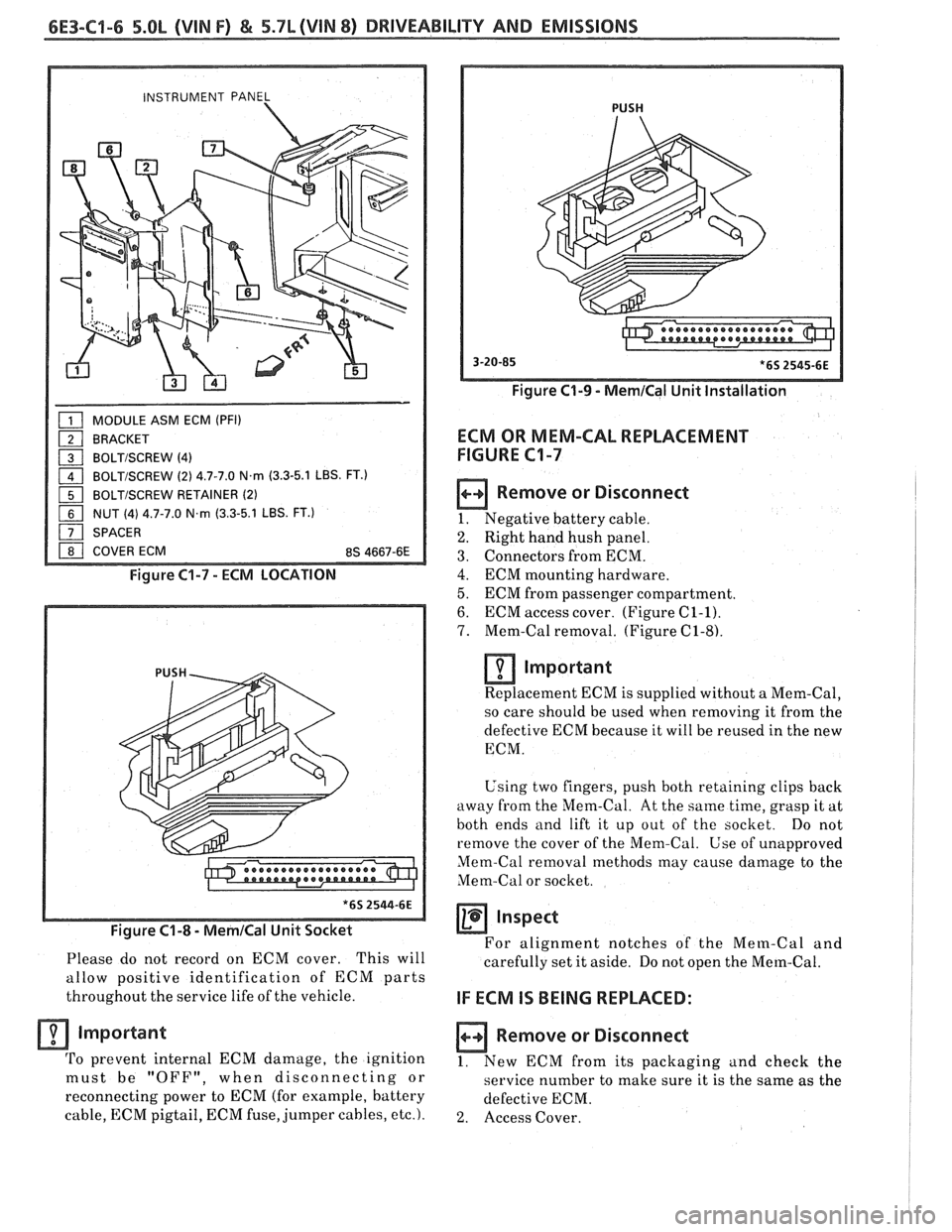
MODULE ASM ECM (PFI)
BRACKET
a BOLTISCREW (4)
1 BOLTISCREW (2) 4.7-7.0 N.m (3.3-5.1 LBS. FT.)
1 BOLTISCREW RETAINER (2)
NUT (4) 4.7-7.0 N.m (3.3-5.1 LBS. FT.)
SPACER
I 1 COVER ECM 8s 4667-6E 1
Figure C1-7 - ECM LOCATION
Figure
C1-8 - MemICal Unit Socket
Please do not record on ECM cover. This will
allow positive identification of ECM parts
throughout the service life of the vehicle.
Important
'I'o prevent internal ECM damage, the ignition
must be "OFF", when
disconnecting or
reconnecting power to ECM (for example, battery
cable, ECM pigtail, ECM fuse, jumper cables,
etc.).
PUSH
Figure C1-9 - MernICal Unit Installation
ECM OR MEM-CAL REPLACEMENT
FIGURE
C1-7
Remove or Disconnect
1. Negative battery cable.
2. Right hand hush panel.
3. Connectors from ECM.
4. ECM mounting hardware.
5. ECM from passenger compartment.
6. ECM access cover. (Figure C1-1).
7. Mem-Cal removal. (Figure C1-8).
lmportant
Replacement ECM is supplied without a Mem-Cal,
so care should be used when removing it from the
defective ECM because it will be reused
in the new
ECM.
Using two fingers, push both retaining clips back
away from the Mem-Cal. At the
same time, grasp it at
both ends and lift it up out of the socket. Do not
remove the cover of the Mem-Cal.
Use of unapproved
Mem-Cal removal methods may cause damage to the
Mem-Cal or socket.
Inspect
For alignment notches of the Mem-Cal and
carefully set it aside. Do not open the
Mern-Cal.
IF ECM IS BEING REPLACED:
Remove or Disconnect
1. New ECM from its packaging and check the - -
service number to make sure it is the same as the
defective ECM.
2. Access Cover.
Page 883 of 1825
6E3-C1-8 5.OL (VIN F) & 5.7L (VIN 8) DRIVEABILITY AND EMISSIONS
MAF SENSOR Install or Connect
Replacement of the MAF sensor is shown in
Figure C1-10.
MAF SENSOR POWER &
BURN-OFF RELAY
Refer to Figure C1-11 for relay location
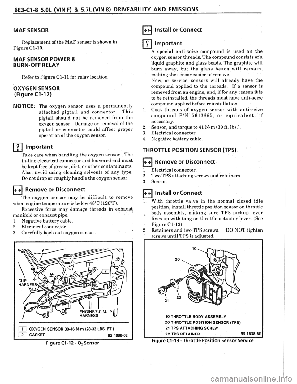
OXYGEN SENSOR
(Figure
C1-12)
NOTICE: The oxygen sensor uses a permanently
attached pigtail and connector. This
pigtail should not be removed
from the
oxygen sensor. Damage or removal of the
pigtail or connector could affect proper
operation of the oxygen sensor.
Important
Take care when handling the oxygen sensor. The
in-line electrical connector and louvered end must
be kept free of grease, dirt, or other contaminants.
Also, avoid using cleaning solvents of any type.
Do not drop or roughly handle the oxygen sensor.
Remove or Disconnect
The oxygen sensor may be difficult to remove
when engine temperature is below 48°C (120°F).
Excessive force may damage threads in exhaust
manifold or exhaust pipe.
1. Negative battery cable.
2. Electrical connector.
3. Carefully
back out oxygen sensor.
OXYGEN SENSOR 38-46 N.rn (28-33 LBS. FT.)
Figure C1-12 - 0, Sensor
Important
A special anti-seize compound is used on the
oxygen sensor threads. The compound consists of
a
liquid graphite and glass beads. The graphite will
burn away, but the glass beads will remain,
making the sensor easier to remove.
New, or service, sensors will already have the
compound applied to the threads. If a sensor is
removed from an engine, and, if for any reason it is
to be reinstalled, the threads must have anti-seize
compound applied before reinstallation.
1. Coat threads of oxygen sensor with anti-seize
compound
PIN 5613695, or equivalent, if
necessary.
2. Sensor, and torque to 41 N*m (30 ft. lbs.).
3. Electrical connector.
4. Negative battery cable.
THROTTLE POSITION SENSOR (TPS)
Remove or Disconnect
1 Electrical connector.
2. Two TPS attaching screws and retainers.
3. Sensor.
Install or Connect
1. With throttle valve in the normal closed idle
position, install throttle position sensor on throttle
body assembly, making sure TPS
picltup lever
lines up with tang on throttle actuator lever. (See
Figure
C1-13)
2. Retainers and two TPS screws. DO NOT tighten
screws until TPS is adjusted.
10 THROTTLE BODY ASSEMBLY
20 THROTTLE POSITION SENSOR (TPS)
21 TPS ATTACHING SCREW
Figure
C1-13 - Throttle Position Sensor Service
Page 891 of 1825
6E3-CZ-4 5.OL (VIN F) & 5.7L(VIN 8) DRIVEABILITY AND EMISSIONS
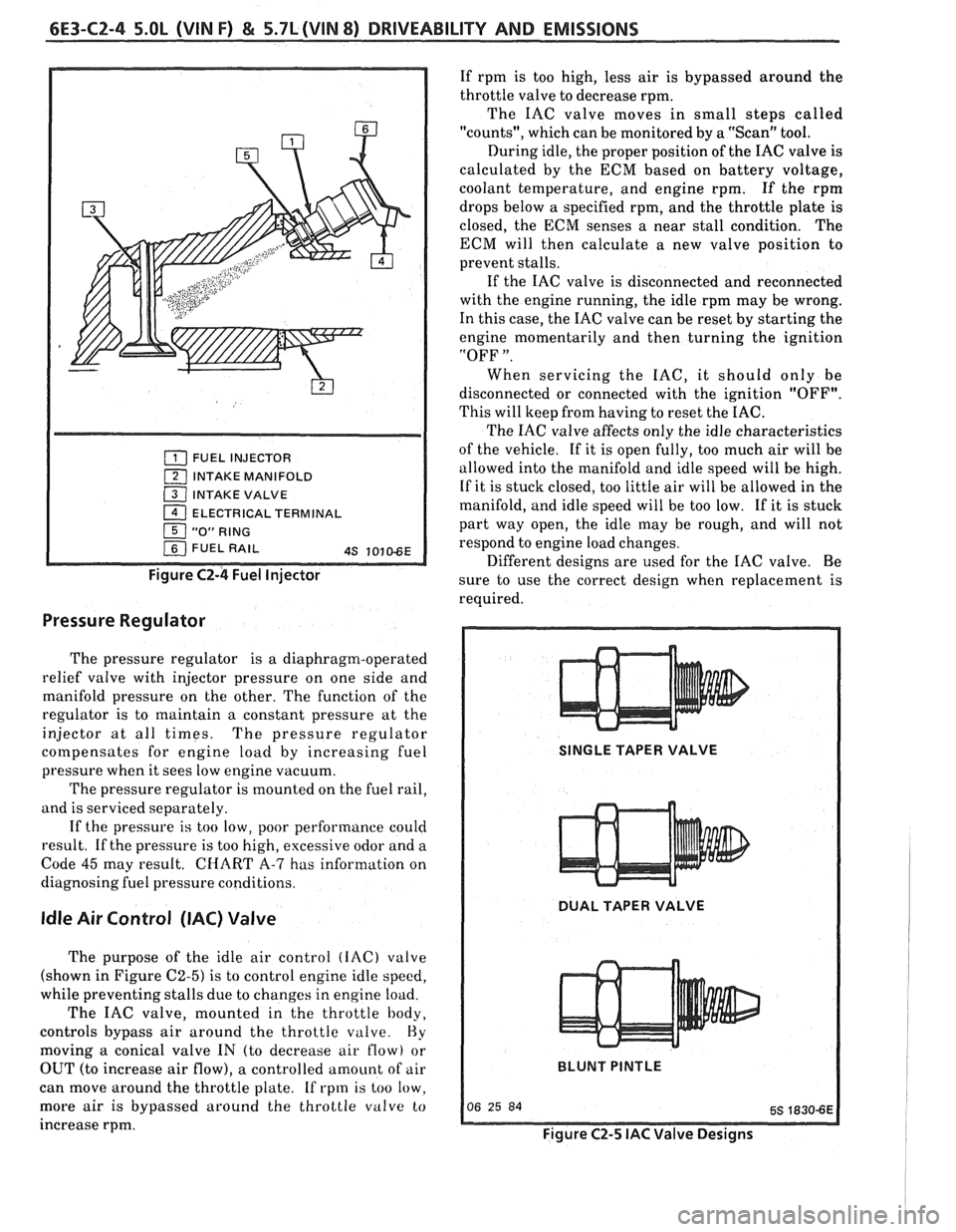
FUEL INJECTOR
1 INTAKE MANIFOLD
( INTAKE VALVE
1 ELECTRICAL TERMINAL
Figure C2-4 Fuel Injector
Pressure Regulator
The pressure regulator is a diaphragm-operated
relief valve with injector pressure on one side and
manifold pressure on the other. The function of the
regulator is to maintain a constant pressure at the
injector at all times. The pressure regulator
cotnpensates for engine load by increasing fuel
pressure when it sees low engine vacuum.
The pressure regulator is mounted on the fuel rail,
and is serviced separately.
If the pressure
is too low, poor performance could
result. If the pressure is too high, excessive odor and a
Code
45 may result. CHART A-7 has information on
diagnosing fuel pressure conditions.
Idle Air Control (IAC) Valve
The purpose of the idle air control (IAC) valve
(shown in Figure
C2-5) is to control engine idle speed,
while preventing stalls due to changes in engine load.
The IAC valve, mounted in the throttle body,
controls bypass air around the throttle
valve. Hy
moving a conical valve IN (to decrease air flow) or
OUT (to increase air flow), a controlled amount of air
can move around the throttle plate. If rpm is too low.
more air
is bypassed around the throttle valve to
increase rpm. If
rpm is too high, less air is bypassed around the
throttle valve to decrease rpm.
The IAC valve moves in small steps called
"counts", which can be monitored by a "Scan" tool.
During idle, the proper position of the IAC valve is
calculated by the ECM based on battery voltage,
coolant temperature, and engine rpm. If the rpm
drops below
a specified rpm, and the throttle plate is
closed, the ECM senses a near stall condition. The
ECM will then calculate a new valve position to
prevent stalls.
If the IAC valve is disconnected and reconnected
with the engine running, the idle rpm may be wrong.
In this case, the IAC valve can be reset by starting the
engine momentarily and then turning the ignition
"OFF
".
When servicing the IAC, it should only be
disconnected or connected with the ignition "OFF".
This will keep from having to reset the IAC.
The IAC valve affects only the idle characteristics
of the vehicle. If it is open fully, too much air will be
allowed into the manifold and idle speed will be high.
If it is stuck closed, too little air will be allowed in the
manifold, and idle speed will be too low. If it is stuck
part way open, the idle may be rough, and will not
respond to engine load changes.
Different designs are used for the IAC valve. Be
sure to use the correct design when replacement is
required.
SINGLE TAPER VALVE
DUAL TAPER VALVE
BLUNT
PINTLE
Figure C2-5 IAC Valve Designs
Page 894 of 1825
DRIVEABILITY AND EMISSIONS 5.OL (VIN F) & 5.7L (VIN 8) 6E3-C2-7
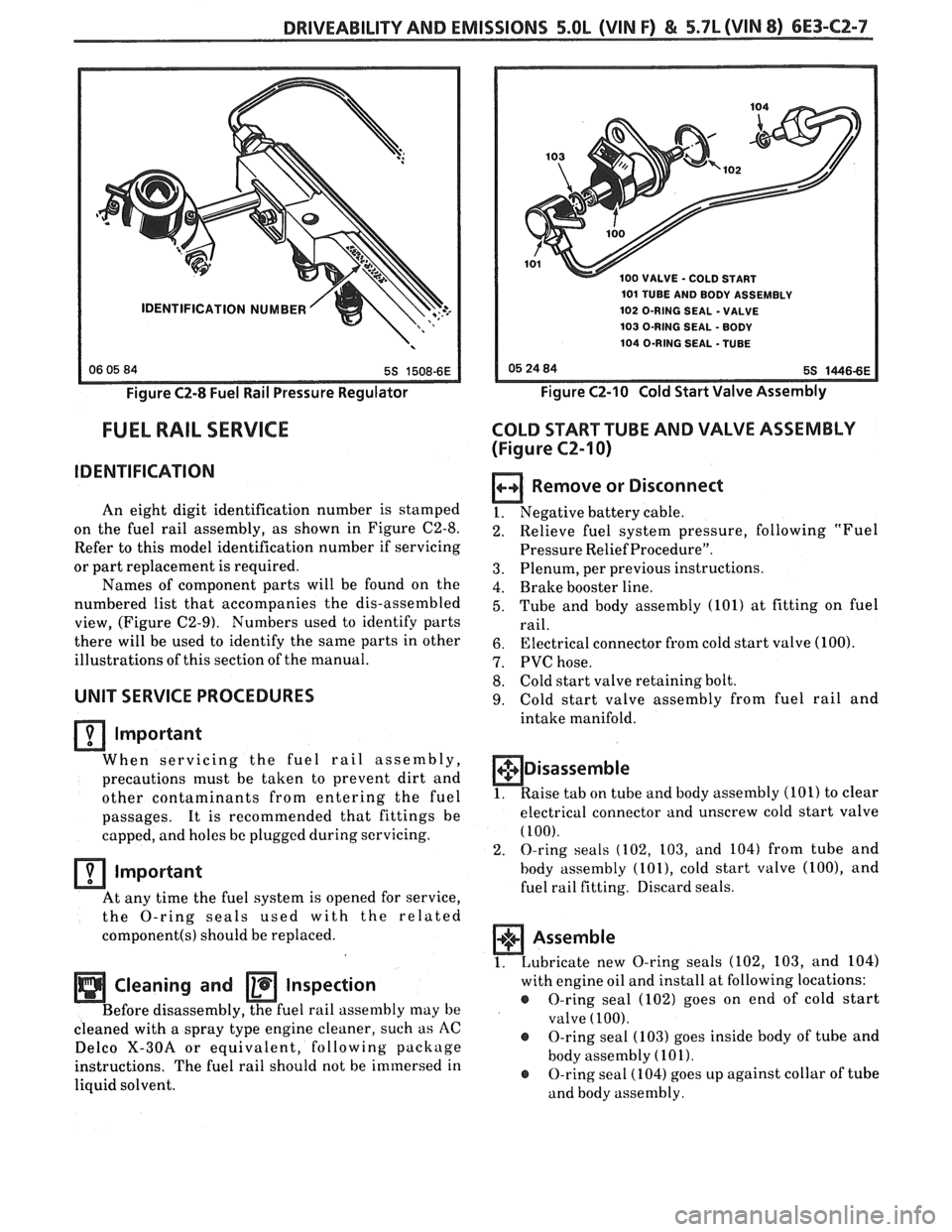
Figure C2-8 Fuel Rail Pressure Regulator
FUEL RAIL SERVICE
IDENTIFICATION
An eight digit identification number is stamped
on the fuel rail assembly, as shown in Figure C2-8.
Refer to this model identification number if servicing
or part replacement is required.
Names of component parts will be found on the
numbered list that accompanies the dis-assembled
view, (Figure C2-9). Numbers used to identify parts
there will be used to identify the same parts in other
illustrations of this section of the manual.
UNIT SERVICE PROCEDURES
lrnportant
When servicing the fuel rail assembly,
precautions must be taken to prevent dirt and
other contaminants from entering the fuel
passages. It is recommended that fittings be
capped, and holes
be plugged during servicing.
Important
At any time the fuel system is opened for service,
the
O-ring seals ised with the related
component(s) should be replaced.
Cleaning and Inspection
Before disassembly, the fuel rail assenlbly may be
cleaned with a spray type engine cleaner, such as
AC
Delco X-30A or equivalent, following
package
instructions. The fuel rail should not be immersed in
liquid solvent.
0 VALVE - COLD START
101 TUBE AND BODY ASSEMBLY
102 O-RING SEAL
- VALVE
103 O-RING SEAL
- BODY
104 O-RING SEAL -TUBE
Figure CZ-10 Cold Start Valve Assembly
COLD START TUBE AND VALVE ASSEMBLY
(Figure
CZ-I 0)
Remove or Disconnect
1. Negative battery cable. -
Relieve fuel system pressure, following "Fuel
Pressure Relief Procedure".
Plenum, per previous instructions.
Brake booster line.
Tube and body assembly (101) at fitting on fuel
rail.
Electrical connector from cold start valve (100).
PVC hose.
Cold start valve retaining bolt.
Cold start valve assembly from fuel rail and
intake manifold.
+$ Disassemble
1. Raise tab on tube and body assembly (101) to clear
electrical connector and unscrew cold start valve
(100).
2. O-ring seals (102, 103, and 104) from tube and
body assembly
(lOl), cold start valve (loo), and
fuel rail fitting. Discard seals.
1. Lubricate
new O-ring seals (102, 103, and 104)
with engine oil and install at following locations:
@ O-ring seal (102) goes on end of cold start
valve
(100).
@ O-ring seal (103) goes inside body of tube and
body assembly
(101).
@ O-ring seal (104) goes up against collar of tube
and body assembly.
Page 923 of 1825
Install or Connect
1. ESC sensor into engine block.
e Tighten to 14 ft. lbs. (19 Nsm).
2. ESC
wiring harness connector to the ESC sensor.
3. Lower car.
4. Negative battery cable.
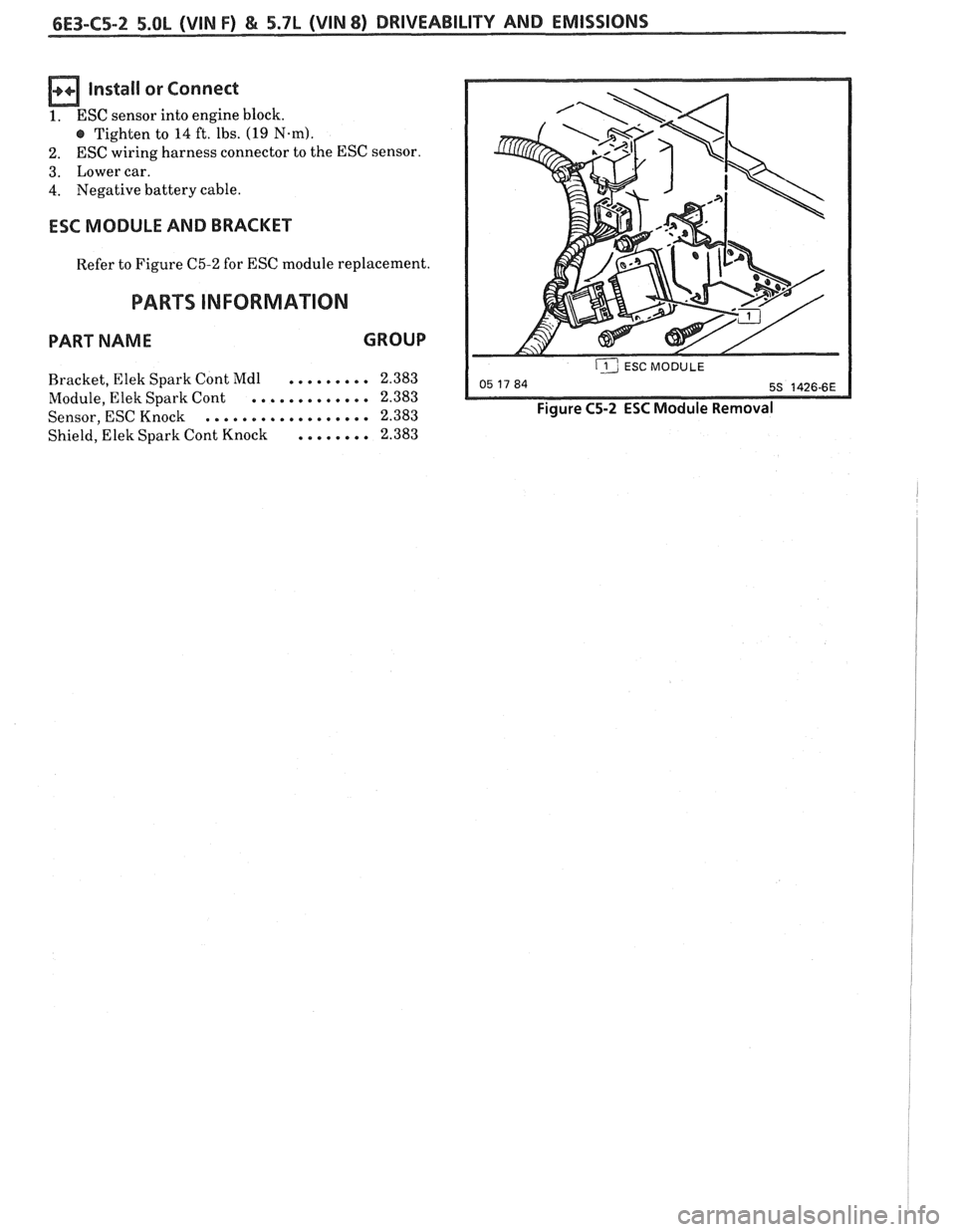
ESC MODULE AND BRACKET
Refer to Figure C5-2 for ESC module replacement.
PARTS INFORMATION
PART NAME GROUP
......... Bracket, Elek Spark Cont Mdl 2.383
............. Module,
Elek Spark Cont 2.383
.................. Sensor, ESC Knock 2.383
Shield, Elek Spark Cont Knock
........ 2.383
ij ESC MODULE --
Figure C5-2 ESC Module Removal
Page 942 of 1825
DWlVEABlLlTV AND EMISSIONS 5.01, QVIN F) & 5.71 (VIN 8) 6E3-C8-1
TRANSMISSION CONVERTER CLUTCH (KC) SYSTEM
AND MANUAL "TRANSMISSION SHlFT LBGH"O"=Ob ONLY
CONTENTS
................ GENERAL DESCRIPTION C8-1 DIAGNOSIS ....................... .. C8-1
........ PURPOSE ......................... CS-1 SHIFT LIGHT (MIT) DESCRIPTION C8-1
....................... OPERATION C8-1 DIAGNOSIS ......................... CS-1
OM-CAR SERVICE ..................... C8-1
GENERAL DESCRIPTION
PURPOSE
The transmission converter clutch (TCC) system
uses
a solenoid operated valve in the automatic
transmission to couple the engine flywheel to the
output shaft of the transmission thru the torque
converter. This reduces the slippage losses in the
converter, which increases fuel economy.
OPERATION
For the converter clutch to apply, two conditions
must be met:
e Internal transmission fluid pressure must be
correct. For information on internal transmission
operation, see Section
"7A". This section will
cover only the electrical operation of the TCC
system.
@ The ECM grounds a switch internally to turn
"ON" a solenoid in the transmission. This moves a
check ball, which will allow the converter clutch
to apply, if the hydraulic pressure is correct, as
described above.
The ECM controls the TCC apply solenoid by
looking at several sensors:
@ Speedo Buffer Sensor (also called Vehicle Speed
Sensor
(VSS) Speed must be above a certain value
before the clutch can apply.
@ Coolant Temperature Sensor Engine must be
warmed
LIP before clutch can apply about 65" C
(149°F).
Throttle Position Sensor (TPS) After the
converter clutch applies, the ECM uses the
information
from the TPS to release the clutch
when the car is accelerating or decelerating at
a
certain rate.
The brake switch
is also part of the 'I'CC circuit as
it will remove battery voltage to the
'FCC solenoid
when the brake pedal is depressed.
@ Gear Select Switch The 4th gear switch is used to
send a signal to the ECM telling it when the
transmission is in 4th
gear
The ECM uses this information to vary the conditions
under which the clutch applies or releases. However,
the transmission does not have to be in fourth gear in
order for the ECM to turn the clutch "ON".
If the converter clutch is applied at all times, the
engine will stall immediately, just as in a manual
transmission with the clutch applied.
If the converter
clutch does not apply, fuel
ecomony may be lower than expected. If the vehicle
speed sensor fails, the TCC will not apply. If the 4th
gear switch does not operate, the TCC may not apply
at the right time.
DIAGNOSIS
The diagnosis of the TCC system is covered in
CHART C-$A. If the ECM detects a problem in the
system, a Code 24 should set. In this case, see Code 24
CHART.
SHIFT LIGHT (MR) DESCRIPTION
The purpose of the shift light is to provide a
display which indicates the optimum fuel economy
point for up shifting the manual transmission based
on engine speed and load. The display is
a lamp on the
instrument panel. Activation
of the ECM driver turns
the lamp "ON".
DIAGNOSIS
The shift light circuit can be checked using
CEIAR'I' C-8B.
ON-CAR SERVICE
See Section "8B" if the shift light bulb needs
replacement.
See Section
"GE" to repair wiring problem.
@ See Section "C- 1" if ECM is to be replaced.
Page 1140 of 1825
5-SPEED 77MM TRANSMISSION 7B-3
ON-VEHICLE SERVICE
SHlR CONTROL LEVER
Remove or Disconnect
1. Screws from transmission shift lever boot
retainer and slide boot up lever.
2. Shift lever attaching bolts at transmission and
remove lever.
NOTICE: The upper lever is no longer threaded
to the lower lever. The levers are bonded
together. Separation of the levers will damage the
shifter requiring replacement of the shifter
assembly.
Install or Conned
1. Shift lever and attaching bolts to transmission.
2. Shift lever boot, boot retainer and retainer
screws to transmission.
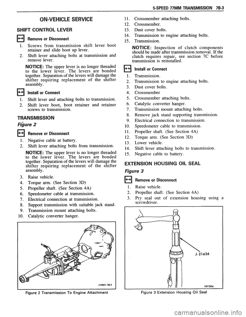
~ibure 2
Remove or Disconnect
1. Negative cable at battery.
2. Shift lever attaching bolts from transmission.
NOTICE: The upper lever is no longer threaded
to the lower lever. The levers are bonded
together. Separation of the levers will damage the
shifter requiring replacement of the shifter
assembly.
3. Raise vehicle.
4. Torque arm. (See Section 3D)
5. Propeller shaft. (See Section 4A)
6. Speedometer cable at transmission.
7. Electrical connection at transmission.
8. Support transmission with suitable jack stand.
9. Transmission mount attaching bolts.
10. Catalytic converter hanger.
Figure 2 Transmission To Engine Attachment
11. Crossmember attaching bolts.
12. Crossmember.
13. Dust cover bolts.
14. Transmission to engine attaching bolts.
15. Transmission.
NOTICE: Inspection of clutch components
should be made after transmission removal. If the
clutch requires repair, see section 7C before
transmission is reinstalled.
Install or Connect
Transmission.
Transmission to engine attaching bolts.
Dust cover bolts.
Crossmember
Crossmember attaching bolts.
Catalytic converter hanger.
Transmission mount attaching bolts.
Remove jack stand supporting transmission.
Electrical connection to transmission. Speedometer cable to transmission.
Propeller shaft. (See Section
4A)
Torque arm. (See Section 3D)
Lower vehicle.
Shift lever attaching bolts to transmission.
Negative cable to battery.
EXTENSlOM HOUSING OIL SEAL
Figure 3
Remove or Disconnect
1 . Raise vehicle.
2. Propeller shaft. (See Section 4A)
3. Pry seal out of extension housing using a
screwdriver.
Figure 3 Extension Housing Oil Seal