1988 PONTIAC FIERO battery replacement
[x] Cancel search: battery replacementPage 1163 of 1825
7C-6 CLUTCH
6. Clutch master cylinder push rod to clutch pedal.
7. Install brake switch.
8. Install hush panel.
9. Install steering column trim cover.
10. Install clutch reservoir to bracket.
1 1. Hoist vehicle.
12. Pilot slave cylinder into clutch fork.
NOTICE: With a new system, the slave cylinder
contains a shipping strap that pre-positions the
push rod for installation, and also provides a
bearing insert.
Follojving installation of the slave
cylinder, the first actuation of the clutch pedal will
break the shipping strap and give
normal system
operation.
13. Install slave cylinder and heat shield to bell
housing.
14.
Lojver vehicle.
15. Connect negative battery cable.
CLUTCH ASSEMBLY
Removal
1. Remove the transmission as outlined in
transmission section.
2. Remove the slave cylinder heat shield and slave
cylinder
from flywheel housing.
3. Reniove the flywheel housing.
4. Slide clutch fork from ball stud and remove fork
from dust boot. Ball stud is threaded into clutch
housing and is easily replaced, if necessary.
5. Install Tool 5-33169 to support the clutch
assen~bly during removal. Look for mark or white
painted letter on clutch cover and
"X" mark on
flywheel. If
"Xu or letter is not evident, mark
flywheel and clutch cover for indexing purposes
during installation.
6. Loosen clutch-to-flywheel attaching bolts evenly
1 turn at a time until spring pressure is released.
7. Remove clutch and pressure plate assembly.
lnspection
Inspect the flywheel for cracks, heat checking or
other defects. Replace or repair as required.
Installation
Pressure plate and flywheel face, (They should be
free of oil, grease, metal deposits or burned spots.)
Installation
1. Position clutch disc and pressure plate in relative
installed position and support them with
alignment Tool J-33169 or a drive gear.
The driven disc is installed with the damper
springs to the transmission. The flywheel side is
marked.
2. Turn clutch assembly until "X" mark or white
painted letter on cover lines up with
"X" mark on flywheel,
then align cover bolt holes to nearest
flywheel holes.
3. Install a bolt in every hole and tighten down
evenly and gradually until tight to avoid possible
clutch distortion. (Cover loads are as high as
1- 1/4 tons).
4. Remove the pilot tool.
5. Unhook clutch fork and lubricate ball socket and
fork fingers at release bearing end with a high
melting point grease such as graphite and
reinstall fork on ball stud.
6. Lubricate recess on inside of release bearing
collar and the clutch fork groove with light coat
of graphite grease. Refer to Figure 7C-6.
7. Install the clutch fork and dust boot into clutch
housing and install release bearing to fork, then
install flywheel housing.
8. Install the transmission as outlined in
transmission section.
9. Install the clutch slave cylinder and bracket.
CLUTCH PEDAL
Removal
Disconnect the negative cable at battery.
Remove the steering column trim cover.
Remove the hush panel from under dash.
If equipped, disconnect cruise control switch at
clutch pedal.
Disconnect the neutral start switch at clutch
pedal.
Renlove the turn signal and hazard flasher
mounting bracket attaching screws.
Disconnect the clutch master cylinder push rod
from pedal.
Remove the nut from clutch pedal pivot bolt. Pull
bolt out far enough for pedal removal.
Inspection
Clean and inspect all components and replace as
necessary. Do not clean bushings with a cleaning
solvent, simply wipe with a clean cloth.
Relubricate all bushings and moving parts.
Installation
1. Reverse the removal procedure.
PILOT BEARING (FIGURE 7C-7)
Replacement
The clutch pilot bearing is an oil impregnated type
bearing pressed into the crankshaft. This bearing requires
attention when the clutch is removed from the vehicle, at
which time it should be cleaned and inspected for exces-
sive wear or damage and should be replaced if necessary.
To remove, install Tool
J 23907 and remove bearing
from crankshaft, as shown in Figure
7C-7. In replacing
this bearing, use Tool
J 1522. Place bearing on pilot of
tool with radius in bore of bearing next to shoulder on tool
and drive into crankshaft. Lubricate with several drops of
machine oil.
Page 1297 of 1825
STARTER AND CHARGING SYSTEM
SYMPTOM TABLE
noid does not click
B: Starter Solenoid clicks, but engine does
A: ENGINE DOES MOT CRANK AND
STARTER SOLENOID DOES NOT
Measure: VOLTAGE
At: STARTER
SOLENOID
Conditions:
Ignition Switch: START
Gear Selector: PARK (Automatic
Transmission) Clutch: DEPRESSED
(Manual
Transmission)
Measure
Between
Correct I For Diagnosis I
I (PPL' & I Battery I See 1 I Ground
S (PPL)
& I I
Starter Motor
mounting I Battery I See 2
bolts
If
all the voltages are correct, replace the
Starter Solenoid. Refer to Section
6D for
replacement procedures.
1. Go to Table 2 (Automatic Transmission)
or Table
3 (Manual Tranmission).
2. Clean the Starter Motor mounting bolts
and Starter Motor. Scrape off any excess
paint, rust or dirt.
COMPONENT LOCATION
....... $223. .......................... IIP harness, above Fuse Bbck.
S224. .......................... IIP harness, near LIP shroud Page-Figure
........ 201- 9-A
A: ENGINE DOES MOT CRANK AND
STARTER SOLENOID DOES NOT
CLICK (TABLE 2-AUTOMATlC
TRANSMISSION)
A: ENGINE DOES MOT CRANK AND
STARTER SOLENOID DOES MOT
CLICK (TABLE 3-MANUAL
TRAMSMiSS16N)
Measure:
VOLTAGE
At: GEAR SELECTOR SWITCH CONNECTOR
(Disconnected)
Condition:
Correct 1 For Diagnosis I
If voltage is correct, go to Table 4.
1. Go to Table 6.
(YEL) &
Ground
At: CLUTCH START SWITCH CONNECTOR
(Disconnected)
Battery See 1
Page 1514 of 1825
THEFT DETERRENT SYSTEM: PASSKEY I i
A: LOCK CYLINDER AND HARNESS
TEST
1. Remove the hush panel under the steering
column. Disconnect the two-cavity connec-
tor in the wire leading into the steering col-
umn. Connect the male and female parts to
the mating connectors on the pigtails from
the 535628 Interrogator or equivalent.
2. Insert the customer's ignition key into the
Ignition Switch Lock Cylinder.
3. Press the On-Off switch on the 535628 Inter-
rogator to the ON position.
* The window above the Key Code Reader
indicates the electrical code for the key
(1 to
15) or
"En error.
Rotate the ignition lock cylinder while the
key is inserted to insure that the correct code
is read in all positions.
- If the code is correct in all positions, proceed
to step 5.
- If code is not correct in all positions, replace
the Lock Cylinder.
* If the window shows "E ", proceed to step 4.
4. Check the customer's ignition key by insert-
ing it in the Key Code Reader on the 535628
Interrogator.
If the Interrogator indicates
"EM, replace
the key with a spare or follow the procedures
under Key Replacement.
If Interrogator shows the electrical code
(1
to 15), replace the Lock Cylinder. (See pro-
cedure following Key Duplication Pro-
cedure). 5.
Set the Key Code Selector on the 535628
Interrogator to the same electrical code
determined in step 3. Turn the Ignition
Switch to START.
If engine starts, reconnect vehicle wiring
and check that the two-cavity connector at
the base of the steering column mates cor-
rectly.
If engine does not start, go to Test B,
Decoder Module Test.
B: PASS KEY DECODER MODULE TEST
(TABLE
1 )
At: PASSKEY DECODER MODULE
CONNECTOR (Disconnected)
Condition:
1 . 1mition switch: START I
Ignition Switch: RUN
Continued from previous c
1. Check the PNKIBLK (439) wire and ClN
Fuse for an open.
2. Check the ORN (440) wire and VATS Fuse
for an open.
3. Check the
BLKIWT (450) wire for an
open.
4. Check the PPL (963) wire for an open.
If
wire is good, replace ECM.
5. Check DK GRN (965) wire for an open. If
wire is good, do Test C.
For Diagnosis
See 1
See 2
See 3
See 4
Measure
Between
A1 (PNKI
BLK) &
Ground
(ORN' &
Ground
A1 (PNKI
BLK)
& I31
(BLKIWNT)
A2 (PPL) &
Bl (BLKI
WNT)
B: PASSKEY DECODER MODULE TEST
Correct
Voltage
Battery
Battery
Battery
5 Volts
(TABLE 2)
Measure: RESISTANCE
At: PASSKEY DECODER MODULE
CONNECTOR (Disconnected)
Conditions: Negative Battery Terminal
Disconnected
r No lCev ln lainition Switch
Measure
- Correct For Diagnosis
Between Resistance
& open circuit
UB2 (BRN) See 1
crank,
replace the PASSKEY Decoder
Module.
-
(Continued in next column) A3 (DK GRN)
& Ground
I . If voltages are correct, go to Table 2.
(Continued in next column)
Battery See 5
Page 1515 of 1825
Continued from previous page)
Note: VVhen the PASSKEY Decoder Module
is replaced, the new key code may not
match the code in the owner's existing
keys. If it does not match, then new
keys must be made. Use the key
duplication procedure.
1. Check YEL (921) and BRN (922) wires for
shorts to ground or between the two
wires.
2. Check
UEL (921) and BRN (922) wires for
an open. If
engine does not crank, go to page 30-0 for
diagnosis of Starter and Charging Circuits.
C3. Reconnect the Starter Enable Relay and
connect a fused jumper from terminal A3
(DK GRN) wire of the PASSKEY Decoder
Module to ground. Ignition Switch to
START.
0 If engine cranks, replace the PASSKEY
Decoder Module.
If engine does not crank, check the DK
GRN (965) wire for
an open. If wire is OK,
replace the Starter Enable Relay.
6: STARTER ENABLE RELAY TEST
D: ECM ENABLE SIGNAL TEST
C2. Connect a fused jumper between terminals
Measure: VOLTAGE
At: STARTER ENABLE RELAY CONNECTOR
(Disconnected)
Condition:
0 Ignition Switch: START Measure:
VOLTAGE
At: PASSKEY DECODER MODULE
CONNECTOR (Connected)
Condition: 0 Ignition Switch: RUN
Measure
Between
&
Ground
&
Ground
Measure
Between I I For Diagnosis ( Voltage
1 I 5Volts I See 1 1
If voltages are correct, go to C2.
1. Check YEL (5) wire for an open. If wire is
good but voltage is not present, go to
8A-30 for diagnosis of Starter and Charg-
ing Circuits.
Correct
Voltage
Battery
Battery
I I
Ignition Switch: START
For Diagnosis
See 1
See 1
0 wait four minutes from last time Ignition
Switch was turned to OFF to
allow PAS-
SKEY Internal timer to reset.
I A2 IPPL)& ) 2 to3Volts I See2 i Ground
If voltages are correct, cranking Fuel
Enable signal is operating normally,
return to Symptom Table.
E (YEL) Vfire and A (DK GR wire 1 1. Check PPL (963) wire for an open. A of the Starter Enable Relay Connector. I I
(Continued in next column)
Ignition Switch to START.
If engine cranks proceed to
63.
Continued from previous column)
2. Replace PASSKEY Decoder Module.
Note: When the PASSKEY Decoder Module
is replaced, the key code
it is set for
may not match the code in the owner's
keys. If
it does not, then new keys
must be made. Use the procedure
under
Duplicgti~n of-Keys2
E: SECURITY INDICATOR OPEN TEST
CONNECTOR (Disconnected)
Condition:
KEY DUPLICATION PROCEDURE
Key Replacement (Spare Key Available)
The 535628 Interrogator or equivalent must
be used to det e
the proper electrical code
of the key.
1. Insert the customer's spare ignition key into
the Key Code Reader on the 535628 Inter-
rogator.
2. Press the On-Off rocker switch to the ON
position.
Page 1516 of 1825
THEFT DETERRENT SYSTEM: PASSKEY
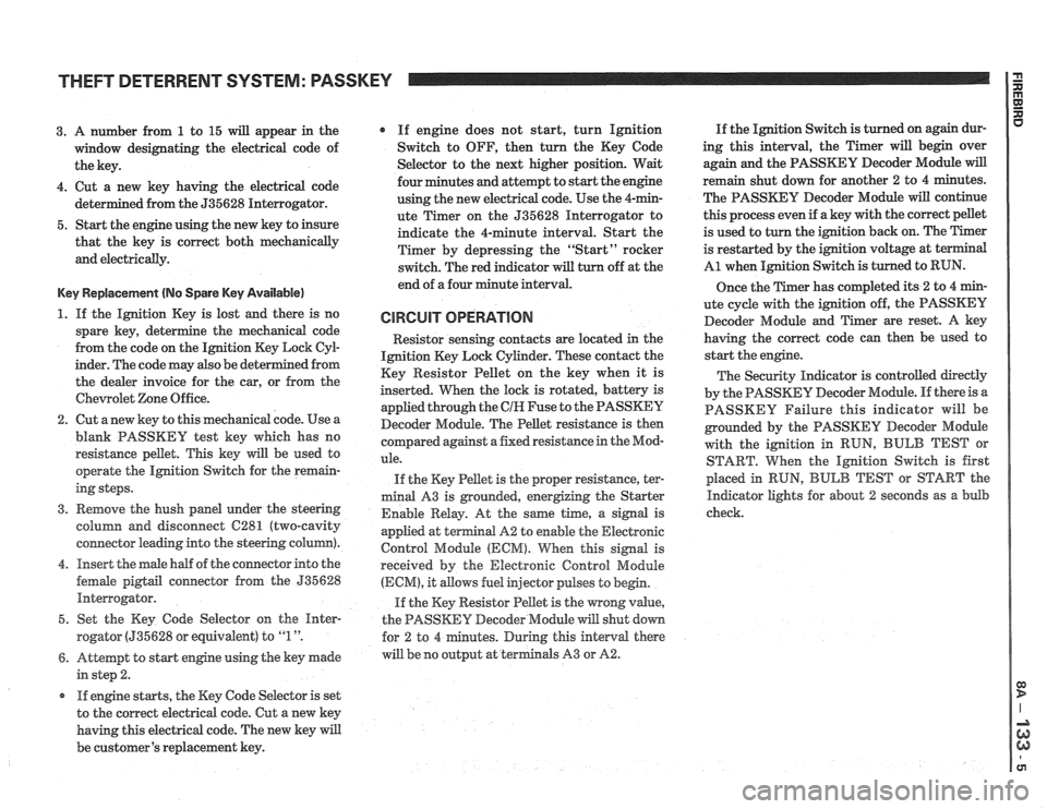
3. A number from 1 to 15 will appear in the
window designating the electrical code of
the key.
4. Cut a new key having the electrical code
ed from the 535628 Interrogator.
5. Start the engine using the new key to insure
that the key is correct both mechanically
and electrically.
Key Replacement (No Spare Key Available)
1. If the Ignition Key is lost and there is no
spare key, determine the mechanical code
from the code on the Ignition Key Lock
CyE
inder. The code may also be det
the dealer invoice for the car, or from the
Chewolet Zone Office.
2. Cut anew key to this mechanical code. Use a
blank PASSKEY test key which has no
resistance pellet. This key will be used to
operate the Ignition Switch for the remain-
ing steps.
3. Remove the hush panel under the steering
column and disconnect
C281 (two-cavity
connector leading into the steering column).
4. Insert the male half of the connector into the
female
pigtail connector from the 535628
Interrogator.
5. Set the Key Code Selector on the
Hnter-
rogator (535628 or equivalent) to "1 ".
6. Attempt to start engine using the key made
in step 2.
r If engine starts, the Key Code Selector is set
to the correct electrical code. Cut a new key
having this electrical code. The new key will
be customer's replacement key.
If engine does not start, turn Ignition
Switch to OFF, then turn the Key Code
Selector to the next higher position. Wait
four minutes and attempt to start the engine
using the new electrical code. Use the 4-min-
ute Timer on the 535628 Interrogator to
indicate the 4-minute interval. Start the
Timer by depressing the "Start" rocker
switch. The red indicator
will turn off at the
end of a four minute interval.
CIRCUIT OPERATION
Resistor senshg contacts are located in the
Ignition Key Lock Cylinder. These contact the
Key Resistor Pellet on the key when it is
inserted. When the lock is rotated, battery is
applied through the
CIH Fuse to the PASSKEY
Decoder Module. The Pellet resistance is then
colnpared against a fixed resistance in the Mod-
ule.
If the Key Pellet is the proper resistance, ter-
minal A3 is grounded, energizing the Starter
Enable Relay. At the
same time, a signal is
appfied at terminal A2 to enable the Electronic
Control Module
(ECM). When this signal is
received by the Electronic Control Module
(ECM), it allows fuel injector pulses to begin.
If the Key Resistor Pellet is the wrong
value,
the PASSKEY Decoder Module will shut down
tes. During this interval there
will be no output at terminals A3 or
A2.
If the Ignition Switch is turned on again dur-
ing this interval, the Timer will begin over
again and the PASSKEY Decoder Module
will
remain shut down for another 2 to 4 minutes.
The PASSKEY Decoder Module will continue
this process even if a key with the correct pellet
is used to turn the ignition back on. The Timer
is restarted by the ignition voltage at
t
A1 when Ignition Switch is turned to RUN.
Once the Timer has completed its
2 to 4 min-
ute cycle with the ignition off, the PASSKEY
Decoder Module and Timer are reset. A key
having the correct code can then be used to
start the engine.
The Security Indicator is controlled directly
by the PASSKEY Decoder Module. If there is a
PASSKEY Failure this indicator will be
grounded by the PASSKEY
Decoder Module
with the ignition in RUN,
BULB TEST or
START. When the Ignition Switch is first
placed in
RUN, BULB TEST or START the
Indicator lights for about 2 seconds as a bulb
check.
Page 1550 of 1825
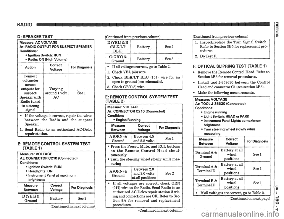
D: SPEAKER TEST (Continued from previous column)
At: RADIO OUTPUT FOR SUSPECT SPEAKER
Ignition Switch: RUN
o an authorized AC-Delco
E: REMOTE CONTROL SYSTEM TEST
(TABLE
1)
Measure: VOLTAGE
At: CONNECTOR C210 (Connected)
Conditions: Ignition Switch: RUN
. Headlights: ON
I r Instrument Panel at maximum I brightness
I Measure I I For Diagnosis ( Between
I & I Battery I See 1 1 Ground I I I I
(Continued in next column)
D (YEL) & B
(BLKILT Battery See 2
BLU)
(GRY) & Battery
Ground See 3
If all voltages correct, go to Table
2.
1. Check YEL (43) wire.
2. Check BLKILT BLU (151) wire for an
open to ground (see schematic).
3. Check GRY
(8) wire.
E: REMOTE CONTROL SYSTEM TEST
(TABLE 2)
At: CONNECTOR 6210 (Connected)
Condition:
Measure
Between
I tz I For Diagnosis
1 I - I
A (ORN) & Between 4.5
Ground and 5.5 volts See 1
Press
the Preset, Mute, and RCL buttons
on the Remote Control
Head simul-
taneously
r Turn the steering wheel slowly while mea-
Between 2.0
at
all positions
If
all voltages are correct, check ORN
(917) wire to the Radio. Send Radio to an
authorized AC-Delco repair station if wir-
ing and connections are OK. Refer to Sec-
tion
9A for removal and replacement
~rocedures. ---- - -
(Continued in next column) (Continued from
previous
column)
Refer to Section 3B5 for replacement pro-
cedures.
2. DoTest F.
F: OPTlCAL SLlPRlNG TEST (TABLE 1 )
e Remove the Remote Control Head. Refer to
Section 3B5 for removal procedures.
r Install tool 5-353630 between the Control
Head and connector
C1 (see section 3B5).
Make the following measurements.
At: TOOL 5-35630 (Connected)
Engine running
0 Light Switch: MEAD or PARK
0 lnstrument Panel Lights at maximum
@ If all voltages are correct, go to Table 2.
(Continued on next page)
Page 1614 of 1825
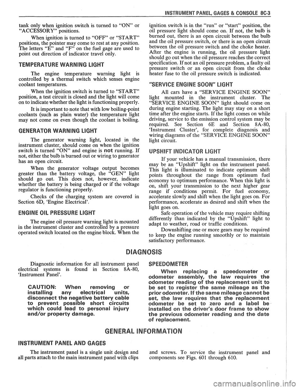
INSTRUMENT PANEL. GAGES & CONSOLE 8C-3
tank only when ignition switch is turned to "ON" or
"ACCESSORY" positions.
When ignition is turned to "OFF" or "START"
positions, the pointer may come to rest at any position.
The letters
"E" and "F" on the fuel gage are used to
point out direction of indicator travel only.
TEMPERATURE WARNING LIGHT
The engine temperature warning light is
controlled by a thermal switch which senses engine
coolant temperatures.
When the ignition switch is turned to "START"
position, a test circuit is closed and the light will come
on to indicate whether the light is functioning properly.
It is important to note that with low boiling-point
coolants (such as plain water) the temperature light
may not come on even though the coolant is boiling.
GENERATOR WARNING LIGHT
The generator warning light, located in the
instrument cluster, should come on when the ignition
switch is turned
"ON" and engine is not running. If
not, either the bulb is burned out or wiring to generator
has an open circuit.
When the generator voltage output becomes
greater than the battery voltage, the
"GEN" light
should go out. This does not, however, indicate
whether the battery is being charged or if the voltage
regulator is functioning properly.
Checks of the charging system are covered in
Section 6D, 'Engine Electrical'.
ENGINE OIL PRESSURE LIGHT
The engine oil pressure warning light is mounted
in the instrument cluster and controlled by a pressure
operated switch located on the engine block. When the ignition switch is
in the
"run" or "start9' position, the
oil pressure light should come on. If not, the bulb is
burned out, there is an open circuit between the bulb
and the oil pressure switch, or there is an open circuit
between the oil pressure switch and the choke heater.
After the engine is running, the oil pressure light
should go out when the oil pressure reaches the correct
specification. If not an oil pressure problem, a faulty oil
pressure switch or an open circuit from the choke
heater fuse to the oil pressure switch is indicated.
"SERVICE ENGINE SOON" LIGHT
All cars have a "SERVICE ENGINE SOON"
light mounted in the instrument cluster. The
"SERVICE ENGINE SOON9' light should come on
during engine starting. The light may stay on
a short
time after the engine starts.
If the light comes on while
driving, service to the emission control system may be
required. See Section
6E and Section 8A-80,
'Instrument Cluster', for complete diagnosis and
wiring diagrams of the
""P;RVICE ENGINE SOON"
light circuit.
UPSHIFT INDICATOR LIGHT
If your vehicle has a manual transmission, there
may be an
''Upshift" light on the instrument panel.
This light is illuminated to indicate optimum shift
points throughout the range from optimum fuel
economy to optimum performance. When this light is
on, shift your transmission to the next higher gear
range if conditions permit. For fuel economy,
accelerate slowly and shift when the light goes on. For
performance, accelerate as desired and shift when the
light goes on.
Safe operation of the vehicle may require shifting
differently than indicated by the "Upshift" light to
adapt to weather, road or traffic conditions.
Downshifting one or more gears may be required
to keep the engine running smoothly or to maintain
satisfactory performance.
DIAGNOSIS
Diagnostic information for all instrument panel
electrical systems is found in Section
8A-80,
'Instrument Panel'.
CAUTION: When removing or
installing any electrical units,
disconnect the negative battery cable
to prevent possible short circuits
which could lead to personal injury
and/or property damage. When
replacing a speedometer or
odometer assembly, the law requires the
odometer reading of the replacement unit to
be set to register the same mileage as the
prior odometer.
if the same mileage cannot be
set, the
law requires that the replacement
odometer be set to zero and a label be
installed on the driver's door frame to show
the previous odometer reading and the date
of replacement.
GENERAL BNFORMATlOM
INSTRUMENT PANEL AND GAGES
The instrument panel is a single unit design and
and screws. To service the instrument panel and
all parts attach to the main instrument panel with clips components see Figs. 601 through 610.
Page 1615 of 1825
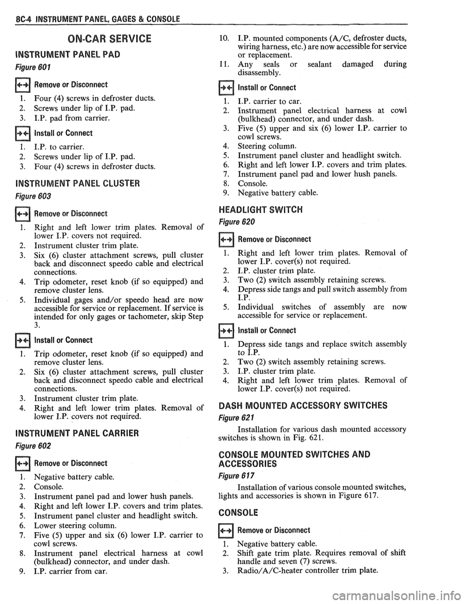
8C.4 INSTRUMENT PANEL, GAGES & CONSOLE
ON-CAR SERVlCE
lNSTRUMEMT PANEL PAD
Figure 601
Remove or Disconnect
1. Four (4) screws in defroster ducts.
2. Screws
under lip of
I.P, pad.
3. I.P. pad from carrier.
lnstall or Connect
1. I.P. to carrier.
2. Screws
under lip of I.P. pad.
3. Four (4) screws in defroster ducts.
INSTRUMENT PANEL CLUSTER
Figure 683
Remove or Disconnect
1. Right and left lower trim plates. Removal of
lower I.P. covers not required.
2. Instrument cluster trim plate.
3. Six (6) cluster attachment screws, pull cluster
back and disconnect speedo cable and electrical
connections.
4. Trip odometer, reset knob (if so equipped) and
remove cluster lens.
5. Individual gages and/or speedo head are now
accessible for service or replacement. If service is
intended for only gages or tachometer, skip Step
3.
Install or Connect
1. Trip odometer, reset knob (if so equipped) and
remove cluster lens.
2. Six
(6) cluster attachment screws, pull cluster
back and disconnect speedo cable and electrical
connections.
3. Instrument cluster trim plate.
4. Right and left lower trim plates. Removal of
lower I.P. covers not required.
INSTRUMENT PANEL CARRIER
Figure 602
Remove or Disconnect
Negative battery cable.
Console. Instrument panel pad and lower hush panels.
Right and left lower I.P. covers and trim plates.
Instrument panel cluster and headlight switch.
Lower steering column.
Five (5) upper and six (6) lower I.P. carrier to
cowl screws.
Instrument panel electrical harness at cowl
(bulkhead) connector, and under dash.
I.P. carrier from car.
10. I.P. mounted components (A/C, defroster ducts,
wiring harness, etc.) are now accessible for service
or replacement.
11. Any seals or sealant damaged during
disassembly.
Install or Connect
I.P. carrier to car.
Instrument panel electrical harness at cowl
(bulkhead) connector, and under dash.
Five (5) upper and six (6) lower I.P. carrier to
cowl screws.
Steering column.
Instrument panel cluster and headlight switch.
Right and left lower I.P. covers and trim plates.
Instrument panel pad and lower hush panels.
Console.
Negative battery cable.
HEADLIGHT SWITCH
Figure 620
Remove or Disconnect
1. Right and left lower trim plates. Removal of
lower I.P.
cover(s) not required.
2. I.P. cluster trim plate.
3. Two (2) switch assembly retaining screws.
4. Depress side tangs and pull switch assembly from
I.P.
5. Individual switches of assembly are now
accessible for service or replacement.
Install or Connect
1. Depress side tangs and replace switch assembly
to I.P.
2. Two
(2) switch assembly retaining screws.
3. I.P. cluster trim plate.
4. Right and
left lower trim plates. Removal of
lower I.P.
cover(s) not required.
DASH MOUNTED ACCESSORY SWITCHES
Figure 62 1
Installation for various dash mounted accessory
switches is shown in Fig.
62 1.
CONSOLE MOUNTED SWITCHES AND
ACCESSORIES
Figure 6 17
Installation of various console mounted switches,
lights and accessories is shown in Figure 617.
CONSOLE
Remove or Disconnect
1. Negative battery cable.
2. Shift gate trim plate. Requires removal
of shift
handle and seven (7) screws.
3. Radio/A/C-heater controller trim plate.