1988 PONTIAC FIERO battery replacement
[x] Cancel search: battery replacementPage 562 of 1825
DRIVEABILITY AND EMISSIONS 5.OL (VIN E) 6EZ-C1-7
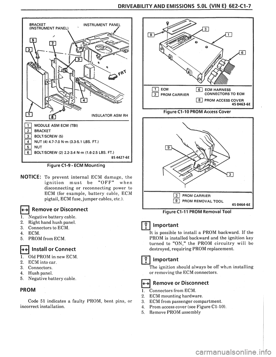
BRACKET
INSTRUMENT PANEL
(INSTRUMENT PANEL) '
MODULE ASM ECM (TBI)
BRACKET
1 BOLTISCREW (5) - 1 NUT (4) 4.7-7.0 N.rn (3.3-5.1 LBS. FT.)
NUT
BOLTISCREW (2) 2.2-3.4 N,rn (1.6-2.5 LBS. FT.)
Figure C1-9 - ECM Mounting
NOTICE: To prevent internal ECM damage, the
ignition must be
"OFF" when
disconnecting or reconnecting power to
ECM (for example, battery cable, ECM
pigtail, ECM fuse, jumper cables,
etc.).
Remove or Disconnect
1. Negative battery cable.
2. Right hand hush panel.
3. Connectors to ECM.
4. ECM.
5. PROM from ECM.
Install or Connect
1. OldPROMinnewECM.
2. ECM into car.
3. Connectors.
4. Hush panel.
5. Negative battery cable.
PROM
Code 51 indicates a faulty PROM, bent pins, or
incorrect installation.
ECM HARNESS
PROM CARRIER CONNECTORS TO ECM
1 PROM ACCESS COVER 45 0463-6E
Figure C1-10 PROM Access Cover
1 PROM REMOVAL TOOL 45 0464-6E
Figure C1-I 1 PROM Removal Tool
Important
It is possible to install a PROM backward. If the
PROM is installed backward and the ignition key
turned to "ON," the PROM circuitry will bc
destroyed, requiring PROM replacement.
lmportant
The ignition should always be off wh~n installing
or removing the ECM connectors.
Remove or Disconnect
1. Connectors from ECM.
2. ECM mounting hardware.
3. ECM from passenger compartment.
4. Prom access cover (see Figure C 1- 10)
5, Remove PROM assembly
Page 564 of 1825
DRIVEABILITY AND EMISSIONS 5.OL (VIN E) 6EZ-C1-9
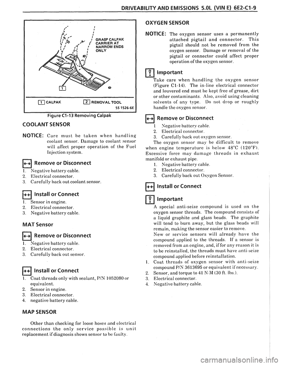
Figure C1-13 Removing Calpak
COOLANT SENSOR
NOTICE: Care must be taken when handling
coolant sensor. Damage to coolant sensor
will affect proper operation of the Fuel
Illjection system.
Remove or Disconnect
1. Negative battery cable.
2. Electrical connector.
3. Carefully back out coolant sensor.
lnstall or Connect
1. Sensor in engine.
2. Electrical connector.
3. Negative battery cable.
MAT Sensor
Remove or Disconnect
I. Negative battery cable.
2. Electrical connector.
3. Carefully back out sensor.
a Install or Connect
I. Coat threads only with sealant, PIN 1052080 or
equivalent.
2. Sensor in engine.
3. Electrical connector.
4, negative battery cable.
OXYGEN SENSOR
NOTICE:
The oxygen sensor uses a permanently
attached pigtail and connector. This
pigtail should not be removed from the
oxygen sensor. Damage or removal of the
pigtail or connector could affect proper
operation of the oxygen sensor.
rn Important
Take care when handling the oxygen sensor - - -
(Figure (21-14). The in-line electrical connector
and louvered end must be kept free of grease, dirt
or other contaminants. Also, avoid using cleaning
solvents of any tvpe.
Do not drop or roughly
handle the oxygen sensor.
a Remove or Disconnect
1 Negative battery cable.
2. Electrical connector.
3. Carefully back out oxygen sensor.
The oxygen sensor may be dit'ficult to remove
when engine temperature is below
48°C (120°F).
Excessive force may damage threads in exhaust
manifold or eshaust pipe.
1. Negative battery cable.
2. Electrical connector.
3. Carefully back out Oxygen Sensor.
lnstall or Connect
rn Important
A s~ecial anti-seize compound is used on the
oxygen sensor threads. The compound consists of
a liquid graphite and glass beads. The graphite
will tend to burn away, but the glass beads will
remain, making the sensor easier to remove.
New or service sensors will already have the
compound applied to the threads. If a sensor is
removed from an engine, and, if for any
reason it is
to be reinstalled, the threads must have
anti-sei~e
compound applied before reinstallation.
1. Coat threads of oxygen sensor with anti-seize
compound
PIN 3613695 or equivalent if neceshary.
2. Sensor, and torque to 41 N,M (30 ft. Ibs.).
3. Electrical connector.
4. Negative battery cable.
MAP SENSOR
Other than checking for loose hoses and electrical
connections the only service possible
is unit
replacement if diagnosis shows sensor to
be faulty.
Page 579 of 1825
6EZ-C2-4 DRIVEABILITY AND EMISSIONS - 5.OL (VIN El
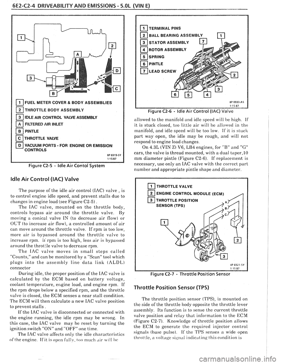
[isj FUEL METER COVER bL BODY ASSEMBLIES
1 THROTTLE BODY ASSEMBLY
1 IDLE AIR CONTROL VALVE ASSEMBLY - FILTERED AIR INLET
PlNTLE
TWRO$TLE VAWE
VACUUM PORTS - FOR ENGINE OR EMISSION
CONTROLS
8P 0319-SY 111 5W7
Figure C2-5 - ldle Air Contol System
ldle Air Control (IAC) Valve
The purpose of the idle air control (IAC) valve , is
to control engine idle speed, and prevent stalls due to
changes in engine load (see Figure
C2-5) .
The IAC valve, mounted on the throttle body,
controls bypass air around the throttle valve By
moving a conical valve IN (to decrease air flow) or
OUT (to increase air flow), a controlled amount of air
can move around the throttle valve. If rpm is too low,
more air is bypassed around the throttle valve to
increase rpm.
11 rpnl is too high, less air is bypassed
around the
throt:le valve to decrease rpm.
The IAC valve moves in small steps called
"Counts," and can be monitored by
a "Scan" tool which
plugs into the assembly line data
link (ALDI,)
connector
During idle, the proper position of the IAC valve is
calculated by the ECM based on battery voltage,
coolant temperature,
ellgine load, and engine rpm. If
the rpm drops below a specified rpm, and the throttle
valve is closed, the ECM senses a near stall condition.
The ECM will then calculate a new IAC valve position
to prevent stalls.
If the IAC valve is disconnected or connected with
the engine running, the idle
rpnl may he wrong. In
this case, the
IAC valve may he reset by turning the
ignition switch "ON" and
"OFF" one time
'I'he IAC valve affects only the idle characteristics
of the engine
If it i.; ol)cltl fullv, too much ,LII. tc 111 I)(>
BALL BEARING ASSEMBLY -
STATOR ASSEMBLY
ROTOR
ASSEMBL
I
SPRING
PlNTLE
LEAD SCREW A
Figure C2-6 - ldle Air Control (IAC) Valve
allowed to the manifold and idle speed will he high. if
it is stuck closed, too little air will be
allo\verl in the
manifold, and idle speed will be too low. If it is stuck
part way open, the idle may be rough, and will not
respond to engine load changes.
On
4.3L (VIN Z) V6, LB4 engines, for "B" and "G"
cars, the valve is thread mounted, with a dual taper,lO
mm diameter pintle (Figure C2-6). If replacement is
necessary, use only an IAC valve with the correct part
number and appropriate pintle shape and diameter.
I THROTTLE VALVE
ENGINE CONTROL MODULE (ECM)
,q
THROTTLE POSITION
SENSOR (TPS)
Figure C2-7 - Throttle Position Sensor
Throttle Position Sensor (TPS)
The throttle position sensor ('I'PS), is mounted on
the side of the throttle body opposite the throttle lever
assembly. Its function is to sense the current throttle
valve position
and relkly that information to the ECM
(Figure (22-7). Knowledge of throttle position allows
lhe ECM to generate the recluired i~jector control
signals (base pulse). If the 'I'PS senses a wide open
throttle,
a voltc\ge sic,ll,~I il~tlic~ttinq this condition 13
Page 580 of 1825

DRIVEABILITY AND EMISSIONS - 5.OL (\/IN El 6EZ-CZ-5
sent to the ECM. The ECM then increases the injector
base pulse width, permitting increased fuel flow.
As the throttle valve rotates in response to
movement of the accelerator pedal, the throttle shaft
transfers this rotational movement to the
'I'PS. A
potentiometer (variable resistor) within the TPS
assembly changes its resistance (and voltage drop) in
proportion to throttle movement.
By applying a reference voltage (5.0 volts) to the
TPS input, a varying voltage (reflecting throttle
position) is available at the TPS output. For example,
approximately 2.5 volts results from a 50% throttle
valve opening (depending on TPS calibration). The
voltage output from the TPS assembly is routed to the
ECM for use in determining throttle position.
FUEL PUMP
The fuel pump is a turbine type, low pressure
electric pump, mounted in the fuel tank. Fuel
is
pumped at a positive pressure (above 62
kPa or 9 psi)
from the fuel pump through the in-line filter to the
pressure regulator in the TBI assembly Excess
fuel is
returned to the fuel tank through the fuel return line.
The fuel pump is attached to the fuel gage sender
assembly. A fuel strainer is attached to the fuel pump
inlet line and prevents dirt particles from entering the
fuel line and tends to separate
water from the fuel
Vapor lock problems are reduced when using an
electric
pump because the fuel is pushed from the tank
under pressure rather than being pulled
under
vacuum, a condition that produces vapor.
An inoperative fuel pump would cause
a. no start
condition. A fuel pump which does not provide enough
pressure can result in poor performance. (See "Fuel
System Pressure Test" procedure).
FUEL PUMP ELECTRICAL CIRCUIT
When the key is first turned "ON" without the
engine running, the ECM turns the
Fuel pump relay
"ON" for two seconds. This builds
up the fuel pressure
quickly. If the engine is not started within two
seconds, the
ECM shuts the fuel pump "OFF" and
waits until the engine starts. As soon as the engine is
cranked, the ECM turns the relay
"ON" and runs the
fuel pump.
As a backup system to the fuel pump relay, the
fuel pump can also be turned on
by the oil pressure
switch. The oil pressure sender has two circuits
internally. One operates the oil pressure indicator or
gage in the instrument cluster,
itnd the other is
anormally open switch which closes when oil pressure
reaches about 28
kPa (4 psi). If the fuel pump relay
fails, the oil pressure switch will run the fuel pump. An
inoperative fuel pump relay can result in long
cranking times, particularly if the engine is cold. The
oil pressure switch will turn on the fuel pump as soon
as oil pressure
reaches about 28 kPa (4 psi).
FUEL CONTROL
Always start with the "Diagnostic Circuit Check"
in Section
"6E2-A". This will reduce diagnosis time
and prevents unnecessary replacement of parts. The
information in this check will direct diagnosis
concerning "Engine
Crunlis But Won't Run" and the
"Fuel Control System," Section
"6E2-C2", including
diagnosis of an injector, pressure regulator,
fuel pump,
fuel
pump relay, and oil pressure switch.
Idle Air Control (IAC) Valve
A "Scan" tool reads IAC position in steps, calletl
"Counts." "0" steps indicates the ECM is commanding
the
IAC to be driven in, to a fully seiltetl position
(minimum idle air).
The higher the number steps, the
more idle air being allowed to pass
by the IAC valve.
cnose Refer to CHART C-2C for information to cliil,
the function of the IAC valve.
Driva bility
Refer to Section "B" for driveability symptoms
related to the fuel control.
ON-VEHICLE SERVICE
GENERAL SEWVICE INFORMATION
CAUTION:
e To prevent personal injury or damage to the
vehicle
as the result sf an accidental start,
disconnect and reconnect the negative
battery cable before and after service is
performed.
@ Also, catch any fuel that leaks out when
disconnecting the fuel lines, by covering the
fittings with
a shop cloth. Place the cloth in
an approved container when work is
complete.
The 'FBI unit repair procedures cover component
replacement with the unit on the vehicle,
tIowever,
throttle body replacement requires that the complete
unit
be removed from the enginc.
Page 588 of 1825
DRIVEABILITY AND EMISSIONS - S.0L (VIN E) 6EZ-C2-13
"THROTTLE BODY INJECTION (TBI) UNIT
Replacement (Figure C2-18)
a Remove or Disconnect
1. THERMAC hose from engine fitting.
2. Electrical connectors to IAC valve, TPS and fuel
injectors.
3. Grommet with wires from throttle body.
4. Throttle linkage, return
spring(s) transmission
control cable and cruise control (wherever
applicable).
5. Vacuum hoses (noting position of hoses) and
bracket.
6. Fuel inlet and return lines (use back-up wrench
J-29698-A or BT-8251-A). Discard o-
rings from
nuts.
7. TBI mounting hardware.
8. TBI flange (manifold mounting) gasket and
discard.
NOTICE: Stuff manifold opening with a rag to
prevent material from entering
engine, and remove old gasket
material from surface of intake
manifold.
Inspect
@ Intake manifold bore for loose parts and foreign
material, etc.
@ Intake manifold sealing surface for cleanliness.
Install or Connect
1. New TBI flange (manifold mounting) gasket.
2.
TI31 with mounting hardware.
Tighten
@ Hardwareto, 16.5N-m( 12Ib. ft.).
3. New o-rings on fuel line nuts
4. Fuel inlet and outlet lines.
Tighten - @ To 23 N.m (17 lb. ft.). (Use back-up wrench
J-29698-A or BT-8251-A to keep TBI nuts
from turning.)
5. Vacuum hoses and bracket.
6. Throttle linkage, return
spring(s) transmission
control cable and cruise control (wherever
applicable).
7. Grommet with wire harness to throttle body.
8. Electrical connectors, making sure connectors are
fully seated and latched.
9. Check to see if accelerator pedal is free by
depressing pedal to the floor
and releasing while
engine is "OFF".
10. With engine "OFF," and ignition "ON," check for
leaks around fuel line nuts.
11. Start engine and check for fuel leaks.
FUEL HOSEIPIPE ASSEMBLIES
Materials
Fuel Lines. These are welded steel tubes, meeting GM
Specification 124-M, or its equivalent. The fuel feed
line is
318" diameter, and the fuel return line is 5/16"
diameter. Do not use copper or aluminum tubing to
replace steel tubing. Those materials do not have
satisfactory durability to withstand normal vehicle
vibr, ii t' lon.
Clamps. These are stainless steel, screw band type
clamps,
#249472, or equivalent.
Coupled Hose. These are not to be repaired and are
replaced
&as an assembly.
Uncoupled Hose. Use only reinforced fuel resistant
hose, made of "fluroelastomer" material.
[lo not use w
hose within 4 inches (100 mm) of any part of the
exhaust system, or within 10 inches
(254 mm) of the
catalytic converter. The hose's inside diameter nus st
match the outside diameter of the steel tubing.
Fuel Line Repair
1. Cut
a piece of fuel hose 4 inches (100 mm) longer
than the section of line to be removed. If
more
than 6 inches (152 tnm) is to be removed, use a .
combination of steel pipe and hose. The
hose
length should not be more than 10 inches total.
2. Cut a section of pipe to be replacccl, with a tube
cutter. C'se the first step of a double flaring tool to
form a bead on the ends
of the pipe and also, on the
new section of pipe, if used.
3. Slide
the hose
clanlps onto the pip2 and push the
hose
2 inches (51 mm) onto each portion of the fuel
pipe. Tighten a
clamp on each side of the repair.
4. Secure
fuel line to the frame.
FUEL PUMP RELAY
(Figure
CZ-19)
The fuel pump relay is mounted in the engine
compartment. Other than checking for loose
connectors, the only service possible is replacement.
OIL PRESSURE SWITCH
(Figure C2-20)
The oil pressure switch is li~ounted on the engine.
This switch is a parallel power supply, with the fuel
pump relay, and will provide battery voltage to the
fuel
pump, after approximately 28 kPa (4 psi) oil
pressure is reached.
Page 629 of 1825

6EZ-C8-4 DRIVEABILITY AND EMISSIONS - 5.OL (VIN E)
I5 WAY (FRONT VIEW)
SPEED INPUT
4rH GEAR SIGNAL
422 TANIBLK
ALDL CONNECTOR
CHART C-8A
TRANSMISSION CONVERTER CLUTCH (TCC)
ELECTRICAL DIAGNOSIS
(Page 1 of 2)
5.OL (VIN E) "F" "SERIES (TBI)
Circuit Description:
The purpose of the automatic transmission torque converter clutch is to eliminate the power loss of the
torque converter, when the vehicle is in a cruise condition. This allows the convenience of the automatic
transmission and the fuel economy of a manual transmission.
Fused battery ignition is supplied to the TCC solenoid through the brake switch. the ECM will engage
TCC
by grounding CKT 422 to energize the solenoid.
TCC will engage when:
- Vehicle speed above 24 mph - Engine at normal operating temperature (above 70°C, 156°F)
- Throttle position sensor output not changing, indicating a steady road speed
- Brake switch closed
Test Description: Numbers below refer to circled solenoids
and relays before installing a
numbers on the diagnostic chart. replacement ECM. Replace
any solenoid or relay
1. Confirms 12 volt supply as well as continuity of that
measures less than 20 ohms.
TCC circuit.
2. Grounding the diagnostic terminal with engine Diagnostic Aids:
"OFF", should energize the capability of the ECM An
engine coolant thermostat that is stuck open or
to control the solenoid. opens
at too low a temperature, may result in an
3. Solenoid coil resistance must measure more than inoperative TCC.
20 ohms. Less resistance will cause early failure
of the ECM
drive^.". Using an ohmmeter, check
the solenoid coil resistance of
all ECM controlled
Page 647 of 1825
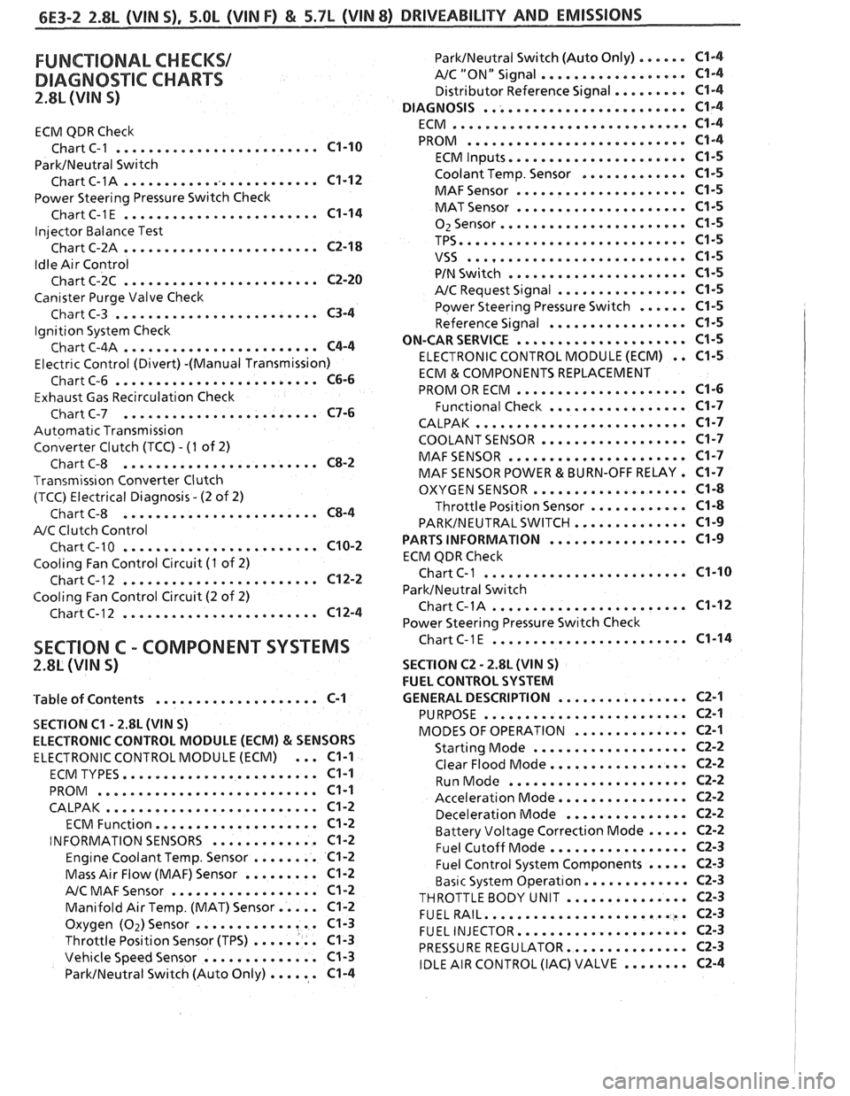
FUNCTIONAL CHECKS/
DIAGNOSTIC CHARTS
2.8L (VIN S)
ECM QDR Check
......................... Chart C-1 C1-10
ParkINeutral Switch
......................... Chart C-1A C1-12
Power Steering Pressure Switch Check
........................ ChartC-1E C1-14
Injector Balance Test
........................ Chart C-2A C2-18
Idle Air Control
........................ Chart C-2C C2-20
Canister Purge Valve Check
......................... Chart C-3 C3-4
Ignition System Check
........................ Chart C-4A C4-4
Electr~c Control (Divert) -(Manual Transmission)
......................... Chart C-6 C6-6
Exhaust Gas Recirculation Check
........................ Chart C-7 C7-6
Automatic Transmission
Converter Clutch (TCC)
. (I of 2)
........................ Chart C-8 C8-2
Transmiss~on Converter Clutch
(TCC) Electrical Diagnosis
. (2 of 2)
........................ Chart C-8 C8-4
A/C Clutch Control
........................ Chart C-10 C10-2
Cooling Fan Control Circuit (I of 2)
........................ Chart C-12 C12-2
Cooling Fan Control Circuit (2 of 2)
........................ Chart C-12 C12-4
ParklNeutral Switch (Auto Only) ...... C1-4
AIC "ON" Signal .................. C1-4
Distributor Reference Signal ......... C1-4
......................... DIAGNOSIS C1-4
............................. ECM C1-4
........................... PROM C1-4
...................... ECM Inputs C1-5
Coolant Temp . Sensor ............. C1-5
..................... MAFSensor C1-5
..................... MAT Sensor C1-5
....................... 02Sensor C1-5
TPS ............................ C1-5
........................... VSS C1-5
...................... PIN Switch C1-5
................ A/C Request Signal C1-5
Power Steering Pressure Switch ...... C1-5
................. Reference Signal C1-5
ON-CAR SERVICE ..................... C1-5
ELECTRONIC CONTROL MODULE (ECM) . . C1-5
ECM & COMPONENTS REPLACEMENT
..................... PROM OR ECM C1-6
................. Functional Check C1-7
CALPAK .......................... C1-7
COOLANT SENSOR .................. C1-7
MAFSENSOR ...................... C1-7
MAF SENSOR POWER & BURN-OFF RELAY . C1-7
................... OXYGEN SENSOR C1-8
Throttle Position Sensor ............ C1-8
PARKINEUTRALSWITCH .............. C1-9
................. PARTS INFORMATION C1-9
ECM QDR Check
................... ... Chart C-1 ... C1-10
ParktNeutral Switch
........................ ChartC-1A C1-12
Power Steering Pressure Switch Check
........................ SECTION C . COMPONENT SYSTEMS ChartC-lE C1-14
2.8L (VIN S) SECTION C2 . 2.8L (WIN S)
FUEL CONTROL SYSTEM
................ 'Table of Contents .................... C-1 GENERAL DESCRIPTION C2-1
SECTION
C1 . 2.8L (VIN S)
ELECTRONIC CONTROL MODULE (ECM)
& SENSORS
ELECTRONIC CONTROL MODULE (ECM) ... C1-1
........................ ECM TYPES C1-1
........................... PROM C1-1
CALPAK .......................... C1-2
.................... ECM Function C1-2
............. INFORMATION SENSORS C1-2
Engine Coolant Temp . Sensor ........ C1-2
Mass Air Flow (MAF) Sensor ......... C1-2
.................. A/C MAF Sensor Cl-2
Manifold Air Temp . (MAT) Sensor ..... C1-2
Oxygen (Oz)Sensor ............... C1-3
Throttle Position Sensor (TPS) ........ C1-3
Vehicle Speed Sensor .............. C1-3
ParkINeutral Switch (Auto Only) ...... C1-4
......................... PURPOSE C2-1
.............. MODES OF OPERATION C2-1
................... Starting Mode C2-2
................. Clear Flood Mode C2-2
...................... Run Mode C2-2
................ Acceleration Mode C2-2
............... Deceleration Mode C2-2
Battery Voltage Correction Mode ..... C2-2
................. Fuel Cutoff Mode C2-3
Fuel Control System Components ..... C2-3
Basic System Operat~on ............. C2-3
THROTTLEBODY UNIT ............... C2-3
......................... FUELRAIL C2-3
..................... FUEL INJECTOR C2-3
............... PRESSURE REGULATOR C2-3
IDLE AIR CONTROL (IAC) VALVE ........ C2-4
Page 650 of 1825
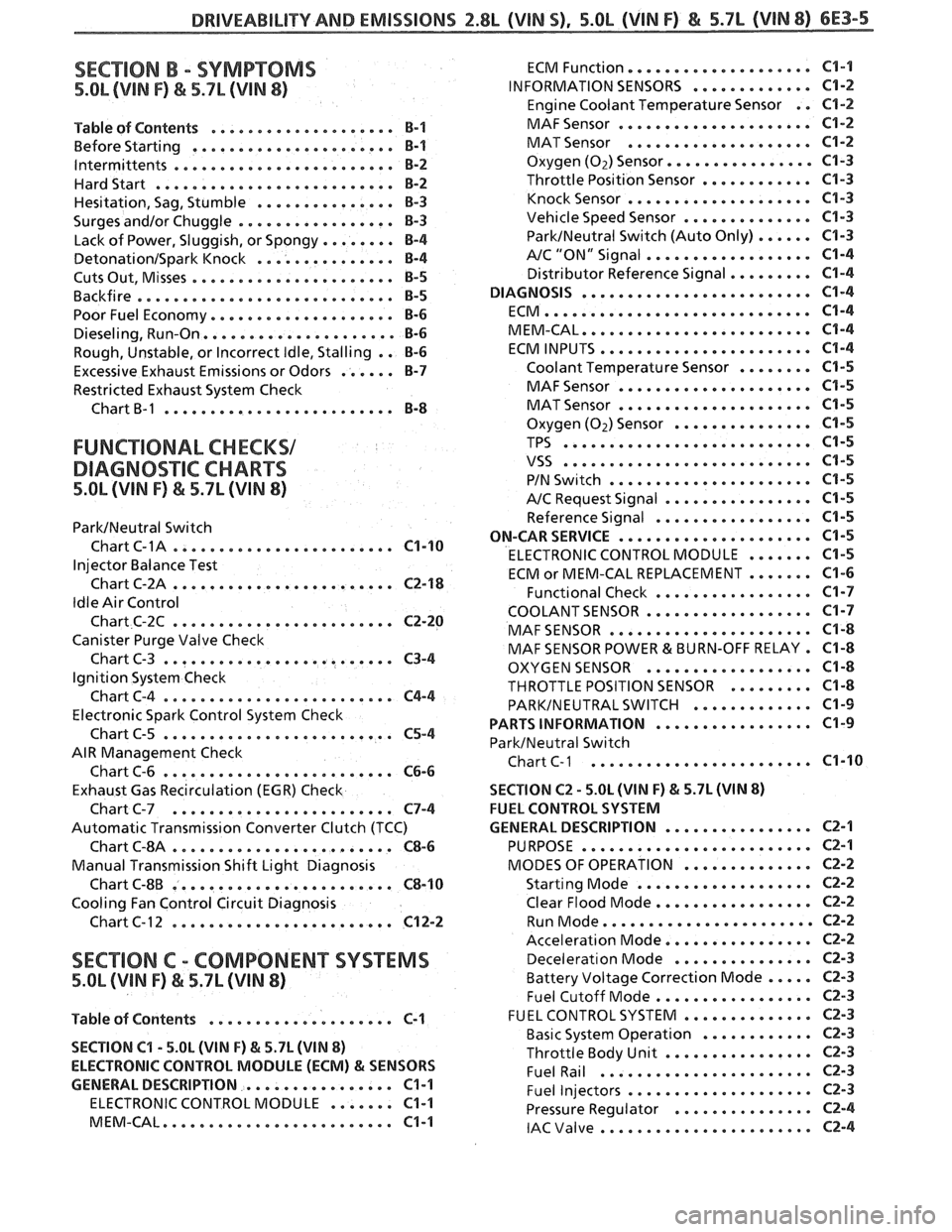
DRIVEABILITVAND EMISSIONS Z.$L (VIN 5). 5.OL (VIN F) & 5.7L (VIN 8) 6E3-5
SECTION B . SYMPTOMS
5.OL (VIN F) & 5.7L (VIN 8)
.................... Table of Contents B-1
................... Before Starting ... B-1
. lntermittents .................... ... B-2
Hardstart .......................... B-2
............... Hesitation. Sag. Stumble 8-3
Surges andlor Chuggle ................. B-3
........ Lack of Power. Sluggish. or Spongy 8-4
DetonationISpark Knock ............... B-4
...................... Cuts Out. Misses €3-5
Backfire ............................ B-5
Poor Fuel Economy .................... B-6
Dieseling. Run.On ..................... 8-6
Rough. Unstable. or Incorrect Idle. Stalling . . B-6
Excessive Exhaust Emissions or Odors ...... B-7
Restricted Exhaust System Check
Chart
B-1 ......................... B-8
FUNCTIONAL CHECKS1
DIAGNO%"FIC CHARTS
5.OL (VIN F) & 5.7L (WIN 8)
ParkINeutral Switch
. Chart C-1A .................... ... C1-10
Injector Balance Test
Chart C-2A
........................ C2-18
Idle Air Control
Chart C-2C
........................ C2-20
Canister Purge Valve Check
Chart C-3
......................... C3-4
Ignition System Check
ChartC-4
......................... C4-4
Electronic Spark Control System Check
Chart C-5
......................... C5-4
AIR Management Check
Chart C-6
......................... C6-6
Exhaust Gas Recirculation (EGR) Check
Chart C-7
........................ C7-4
Automatic Transmission Converter Clutch (TCC)
Chart
6-814 ........................ C8-6
Manual Transmission Shift Light Diagnosis
Chart C-8B
........................ C8-10
Cooling Fan Control Circuit Diagnosis
Chart C- 1 2
........................ C12-2
SECTION C . COMP0NEN"I"SVSTEMS
5.OL (VIN F) & 5.7L (WIN 8)
Table of Contents .................... C-1
SECTION
C1 . 5.OL (VIN F) & 5.7L (VIN 8)
ELECTRONIC CONTROL MODULE (ECM)
81 SENSORS
GENERAL DESCRIPTION
................ C1-1
ELECTRONIC CONTROL MODULE ....... C1-1
MEM.CAL ......................... C1-1
................... ECM Function. C1-1
INFORMATION SENSORS ............. C1-2
Engine Coolant Temperature Sensor . . C1-2
..................... MAF Sensor C1-2
.................... MAT Sensor C1-2
Oxygen (Oz) Sensor ..............a. C1-3
Throttle Position Sensor ............ C1-3
.................... Knock Sensor C1-3
Vehicle Speed Sensor .............. C1-3
ParkINeutral Switch (Auto Only) ...... C1-3
.................. A/C "ON" Signal C1-4
Distributor Reference Signal ......... C1-4
DIAGNOSIS ......................... C1-4
ECM ............................. C1-4
MEM.CAL ......................... C1-4
ECM INPUTS ....................... C1-4
Coolant Temperature Sensor ........ C1-5
..................... MAF Sensor C1-5
..................... MAT Sensor C1-5
Oxygen (Oz) Sensor ............... C1-5
TPS ........................... C1-5
VSS ........................... C1-5
...................... PIN Switch C1-5
A/C Request Signal ................ C1-5
Reference Signal ................. C1-5
ON-CAR SERVICE ..................... C1-5
ELECTRONIC CONTROL MODULE ....... C1-5
ECM or MEM-CAL REPLACEMENT ....... C1-6
Functional Check ................. C1-7
COOLANTSENSOR .................. C1-7
MAF SENSOR ...................... C1-8
MAF SENSOR POWER & BURN-OFF RELAY . C1-8
OXYGEN SENSOR .................. C1-8
THROTTLE POSITION SENSOR ......... C1-8
PARKINEUTRAL SWITCH ............. C1-9
................. PARTS INFORMATION C1-9
ParkINeutral Switch
Chart
C-1 ..................... ... C1-10
SECTION C2 . 5.0L (WIN F) & 5.7L (WIN 8)
FUEL CONTROL SYSTEM
................ GENERAL DESCRIPTION C2-1
......................... PURPOSE C2-1
.............. MODES OF OPERATION CZ-2
................... Starting Mode C2-2
Clear Flood Mode ................. CZ-2
....................... Run Mode CZ-2
................ Acceleration Mode C2-2
............... Decelerat~on Mode C2-3
Battery Voltage Correction Mode ..... C2-3
................. Fuel Cutoff Mode C2-3
.............. FUEL CONTROL SYSTEM C2-3
............ Basic System Operation CZ-3
................ Throttle Body Unit CZ-3
....................... Fuel Rail C2-3
.................... Fuel Injectors CZ-3
............... Pressure Regulator C2-4
....................... IAC Valve 62-4