1988 PONTIAC FIERO battery replacement
[x] Cancel search: battery replacementPage 407 of 1825
6A3-28 V-8 ENGINE
16. Install
radiator and fan shroud and reconnect
radiator and heater hoses.
17. Fill cooling system.
18. Fill
crankcase with oil. See owner's manual for
specifications.
19. Install air cleaner.
20. Install hood.
21. Connect battery cables.
NOTICE: To avoid possible arcing of battery,
connect positive battery cable first.
22. Start engine, check for leaks and check timing.
CRANKSHAFT
The crankshaft can be removed while the engine
is disassembled for overhaul, as previously outlined, or
without complete disassembly.
Removal
With the engine removed from the vehicle and the
transmission and/or clutch housing removed
from the engine, mount engine in stand and
clamp securely.
Remove the oil dip stick and oil dip stick tube, (if
applicable).
Remove the starting motor, clutch assembly (if
equipped) and flywheel.
Remove the spark plugs.
Remove crankshaft pulley and torsional damper.
Remove oil pan and oil pump.
Remove crankcase front cover, and if so
equipped, remove timing chain and camshaft
sprocket.
Check the connecting rod caps for cylinder
number identification. If necessary, mark them.
Remove the connecting rod caps and push the
pistons to top of bores.
Remove main bearing caps and lift crankshaft out
of cylinder block.
Remove rear main bearing oil seal and main
bearings from cylinder block and main bearing
caps.
Cleaning and Inspection
1. Wash crankshaft in solvent and dry with
compressed air.
2. Measure dimensions of main bearing journals and
crankpins with a micrometer for out-of-round,
taper or undersize. (See Specifications.) 3.
Check crankshaft for run-out by supporting at
the front and rear main bearings journals in
"V"
blocks and check at the front and rear
intermediate journals with a dial indicator. (See
Specifications.)
4. Replace or recondition the crankshaft if out of
specifications.
SPROCKET OR GEAR REPLACEMENT
e Remove crankshaft sprocket using Tool
5-5825, install using Tool J-5590.
Installation
1.
Install rear main bearing oil seal in cylinder block
and rear main bearing cap grooves. Install with
lip of seal toward front of engine. Where seal has
two lips install lip with helix towards front of
engine.
2. Lubricate lips of seal with engine oil. Keep oil off
parting line surface.
3. Install main bearings in cylinder block and main
bearing caps then lubricate bearing surface with
engine oil.
4. Install crankshaft, being careful not to damage
bearing surfaces.
5. Recheck bearing clearances using plastigage.
6. Apply a thin coat of brush-on type oil sealing
compound to block mating surface and
corresponding surface of cap only. Do not allow
sealant on crankshaft or seal.
7. Install main bearing caps with arrows pointing
toward front of engine.
8. Torque all except rear main bearing cap bolts to
specifications. Torque rear main bearing cap bolts
to 10-12 lbs. ft. (14-16
N.m)then tap end of
crankshaft, first rearward then forward with a
lead hammer. This will line up rear main bearing
and crankshaft thrust surfaces.
Retorque all main
bearing cap bolts to specifications.
9. Measure crankshaft end play with a feeler gage.
Force crankshaft forward and measure clearance
between the front of the rear main bearing and the
crankshaft thrust surface.
10. Install flywheel and torque to specifications. A
wood block placed between the crankshaft and
cylinder block will prevent crankshaft from
rotating.
Align dowel hole in flywheel with dowel
hole in crankshaft. On vehicles equipped
with automatic transmissions, install
flywheel with the converter attaching pads
towards transmission.
GENERAL DATA
TYPE .................................................................................................................................. 90" V-8
DISPLACEMENT
............................................................................... 305 Cu. In., 350 Cu. In.
......................................................... LITER (VIN) ................................... ...... 5.0, (E), (F), 5.7 (8)
RPO ......................................................................................................................... L03, LB9, L98
BORE ........................................................................................................................ 3.736, 4.000
STROKE
........................... .. ....................................................................................... 3.480, 3.480
COMPRESSION RATIO
................................................................................... 931, 931, 9.5:1
FIRING ORDER .................................................................................................... 1-8-4-3-6-5-7-2
Page 425 of 1825
6B-I4 ENGINE COOLING
SMALL
586826
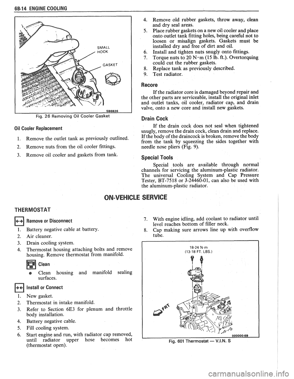
Fig. 26 Removing Oil Cooler Gasket
4. Remove old rubber gaskets, throw away, clean
and dry seal areas.
5. Place rubber gaskets on a new oil cooler and place
onto outlet tank fitting holes, being careful not to
loosen or misalign gaskets. Gaskets must be
installed dry and free of dirt and oil.
6. Install
and tighten nuts snugly onto fittings.
7. Torque nuts
to 20
N.m (15 lb. ft.). Overtorquing
could cut the rubber gaskets.
8. Replace
tank as previously described.
9. Test radiator.
Recore
If the radiator core is damaged beyond repair and
the other parts are serviceable, install the original inlet
and outlet tanks, oil cooler, radiator cap, and drain
valve, onto a new core and install new gaskets.
Drain Cock
Oil Cooler Replacement If the drain cock does not seal when tightened
snugly, remove the drain cock, clean drain and replace.
1. Remove
the outlet tank as previously outlined. If
the body of the draincock is broken, remove the body
from the tank by squeezing the sides together with
2. Remove nuts from the oil cooler fittings.
needle nose pliers (Fig. 9).
Remove oil cooler and gaskets from tank. Special Tools
Special tools are available through normal
channels for servicing the aluminum-plastic radiator.
The universal Cooling System and Cap Pressure
Tester, BT-7518 or J-24460-01, can also be used with
the aluminum-plastic radiator.
ON-VEHICLE SERVICE
THERMOSTAT
Remove or Disconnect
1. Battery negative cable at battery.
2. Air cleaner.
3. Drain cooling system.
4. Thermostat housing attaching bolts and remove
housing. Remove thermostat from manifold.
Clean
Clean housing and manifold sealing
surfaces.
Install or Connect
1. New gasket.
2. Thermostat in intake manifold.
3. Refer
to Section 6E3 for plenum and throttle
body installation.
4. Battery negative cable.
5. Fill cooling system.
6. Start engine and run, with radiator cap removed,
until radiator upper hose becomes hot
(thermostat open). 7.
With
engine idling, add coolant to radiator until
level reaches bottom of filler neck.
8. Cap making sure arrows line up with overflow
tube.
18-24 N,m (13-18 FT. LBS.)
Fig. 601 Thermostat - V.I.N. S
Page 434 of 1825
ENGINE FUEL 6C.3
a Fuel feed and return pipes are secured to the
underbody with clamps and screw assemblies.
The pipes should be inspected occasionally for
leaks, kinks or dents.
e Follow the same routing as the original pipe.
e Pipes must be properly secured to the frame to
prevent chafing. A minimum of 6 mm
(1/4")
clearance must be maintained around a pipe to
prevent contact and chafing.
MPFl Fuel Pipes
Due to the fact that fuel pipes are under high
pressure, these systems require special consideration for service.
Many feed and return pipes use screw couplings
with
"0" Rings. Any time these fittings are loosened
to service or replace components, ensure that:
a A backup wrench is used while loosening and
tightening the fitting.
e Check all "0" rings at fitting locations (if
applicable) for cuts or any damage and replace
any that appear worn or damaged.
e Use correct torque when tightening fittings.
If pipes are replaced always use original
equipment parts, or parts that meet GM
specifications.
Fuel and Vapor Hoses
NOTICE: Fuel and vapor hoses are specially
manufactured. If replacement becomes necessary,
it is important to use only replacement hoses
meeting GM Specification 6163-M. These hoses
are identified with the words "Fluoroelastomer"
on them. Hoses not so marked could cause early
failure, or fail to meet emission standards.
e Do not use rubber hose within 4" of any part of
the exhaust system, or within
10" of the catalytic
converter.
FUEL PUMP
The electric fuel pump is in the fuel tank. The
tank has an outlet for a vapor return system. Any vapor
which forms is returned to the fuel tank along with hot
fuel through a separate line. This greatly reduces any
possibility of vapor lock by keeping cool fuel from the
tank constantly circulating through the fuel pump.
FUEL PUMP RELAY
To control fuel pump operation, a fuel pump
relay is used.
When the ignition switch is turned to "RUN"
position, the fuel pump relay activates the electric fuel
pump for
1.5 to 2.0 seconds to prime the injector(s). If
the ECM does not receive reference pulses from the
distributor after this time, the ECM signals the relay
to turn off the fuel pump. The relay will once again
activate the fuel pump when the
ECM receives
distributor reference pulses.
Fuel Filter
CAUTION: To reduce the risk of fire
and personal injury, it is necessary
to
relieve the fuel system pressure
before servicing fuel system
components. (See Fuel System
Pressure Relief.)
The inline filters can be found on the rear
crossmember of the vehicle. Always use a backup
wrench any time that the fuel filter is removed or
installed. Also make sure that a good
"0" Ring is used
at all screw couple locations. Torque on fittings is
30
N-m (22 lb. ft.).
FUEL TANK
The fuel tank is usually located under the rear of
the vehicle and a number of shapes and sizes are used
depending on the application.
The tank is held in place by two metal straps,
hinged (with a bolt through the hinge) and secured at
the opposite end with a nut and bolt assembly.
Anti-squeak pieces are used on top of the tank to
reduce rattles and other annoying noises.
The fuel tank, cap and lines should be inspected
for road damage, whch could cause leakage. Inspect
fuel cap for correct sealing and indications of physical
damage. Replace any damaged or malfunctioning
parts.
Before attempting service of any type on the fuel
tank, always
(1) remove negative battery cable from
battery, (2) place "no smoking" signs near work areas,
(3) be sure to have C02 fire extinguisher handy, (4)
wear safety glasses and
(5) siphon or pump fuel into an
explosion proof container.
Fuel Filler Gap
The fuel tank filler neck is equipped with a
screw-type cap. The threaded part of the cap requires
several turns counterclockwise to remove. The long
threaded area is designed to allow any remaining fuel
tank pressure to escape while the cap is being removed.
A built-in torque-limiting device prevents
overtightening. To install, turn the cap clockwise until
a clicking noise is heard. This signals that the correct
torque has been reached and the cap is fully seated.
N OTI G E: If a fuel filler cap requires replacement,
use only a cap with the same features. Failure to
use the correct cap can result in a serious
malfunction of the system.
Available on some models is an electric locking
fuel filler cap. Information on this option will be found
in Section
9E.
FUEL TANK FILLER NECK
To help prevent refueling with leaded gasoline,
the fuel filler neck on gasoline engine cars has a built-in
restrictor and deflector. The opening in the restrictor
will only admit the smaller unleaded gas nozzle spout,
which must be fully inserted to bypass the deflector.
Attempted refueling with a leaded gas nozzle or failure
Page 450 of 1825
BATTERY 801-7
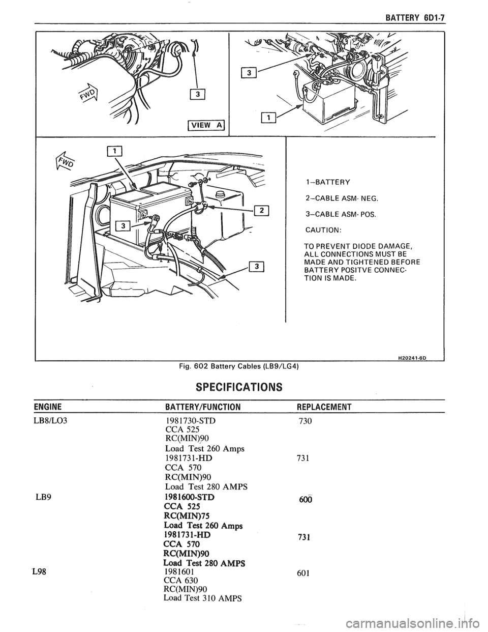
1 -BATTERY
2-CABLE ASM- NEG.
3-CABLE ASM- POS.
TO PREVENT DIODE DAMAGE, ALL CONNECTIONS MUST BE
MADE AND TIGHTENED BEFORE
BATTERY
POSlTVE CONNEC-
TION IS MADE.
Fig.
602 Battery Cables (LBS/LG4)
SPECIFICATIONS
ENGINE BATTERY/FUNCTION REPLACEMENT
LB8lL03 198 1730-STD 730
CCA 525
RC(MIN)90
~oad ~est 260 Amps
1981731-HD
CCA 570
RC(MIN)90
Load Test 280 AMPS
198 1W-STD
CCA 525
RC(MIN)75
Load Test 260 Amps
1981731-HD
CCA 570
RC(MIWW
Load Test 280 AMPS
1981601
CCA 630
RC(MIN)90
Load Test 310 AMPS
Page 460 of 1825
CRANKING SYSTEM BD2-9
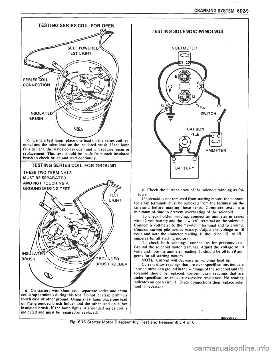
I TESTING SERIES COIL FOR OPEN I
TESTING SOLENOID WINDINGS
c. Us~ng a test lamp. place onelead on the series coil ter-
minal and the other lead on the insulated brush. If the lamp
fails to light. the series coil is open and will require repair or
replacement. This test should be made from each insulated
brush to check brush and lead continuity.
TESTING SERIES COlL FOR GROUND
THESE TWO TERMINALS
MUST BE SEPARATED
d. On starters
withshunt coil. sepanate series and shunt
coil strap terminals during this test. Do not let strap terminals
touch case or other ground. Using a test lamp place one lead
on
he grounded brush holder and the other lead on either
insulated brush. If the lamp lights, a grounded series coil is
indicated and must be repaired or replaced. VOLTMETER
e. Check the current draw of the solenoid winding as fol-
lows:
If solenoid is not removed from starting motor. the connec-
tor
strap terminals must be removed from the terminal on the
solenoid before making these tests. Complete tests in a
minimum of time to prevent overheating of the solenoid.
To check hold-in winding, connect an ammeter in series
with 12-volt battery and the "switch" terminal on the solenoid.
Connect a voltmeter to the "switch" terminal and to ground.
Connect carbon pile across battery. Adjust the voltage to
10 volts and note the ammeter reading. It should be 13 to 19 amperes for all starting motors.
To check both windings. connect as for previous test.
Ground the solenoid motor terminal. Adjust the voltage to 10
volts and note the ammeter reading. It should be
59 to 79 am-
peres for all starting motors.
NOTE: Current will decrease as windings heat up.
Current draw readings that are over specifications indicate
shorted turns or a ground in the windings of the solenoid and the
solenoid should be replaced. Current draw readings that are
under specifications indicate excessive resistance. No reading
indicates an open circuit. Check connections then replace sole-
noid if necessary.
H20255.6D
Fig. 606 Starter Motor Disassembly, Test and Reassembly 4 of 6
Page 473 of 1825
684.4 IGNITION SYSTEM
a spark plug wire from a spark plug, twist the 4. Do not wipe grease from module, or distributor
boot on the spark plug and pull
on the boot to base,
if same module is to be replaced.
remove the wire, or use a special tool designed to
remove spark plug boots.
Install or Connect
Remove or Disconnect
1. Ignition switch battery feed wire and tachometer
lead (if equipped) from distributor cap. Also
release the coil connectors from the cap. (DO
NOT use a screwdriver or tool to release the
locking tabs.)
2. Distributor cap by turning four screws
counterclockwise. Move cap out of the way.
3. Four-terminal ECM harness from distributor.
4. If necessary, remove secondary wires from cap,
release wiring harness latches and remove wiring
harness retainer. The spark plug wire numbers
are indicated on the retainer.
5. Distributor clamp screw and hold-down clamp.
6. Note position of rotor, then pull distributor up
until rotor just stops turning counterclockwise
and again note position of rotor.
To insure correct timing of the distributor,
the distributor must be INSTALLED with
the rotor correctly positioned as noted.
If the engine was accidentally cranked after the
distributor was removed, the following procedure can
be used for installing:
1. Remove No. 1 spark plug.
2. Place finger over No. 1 spark plug hole and crank
engine slowly until compression is felt.
3. Align timing mark on pulley to "0" on engine
timing indicator.
4. Turn rotor to point between No. 1 and No. 8
spark plug towers on distributor cap on V8
engines, between No. 1 and No. 6 on V6 engines,
and No.
1 and No. 4 on 4 cylinder engines.
5. Install distributor and connect ignition feed wire.
6. Install distributor cap and spark plug wires.
7. Check engine timing (see Set Ignition Timing).
Install or Connect
1. Insert distributor, positioning rotor as removed.
2. Distributor hold-down clamp and screw.
3. Wiring harness retainer and secondary wires, if
removed.
4. ECM harness connector.
5. Distributor cap.
6. Coil connectors.
7. Battery wire and tachometer lead, if equipped.
Module
It is not necessary to remove the distributor from
car.
Remove or Disconnect
1. Distributor cap and rotor.
2. Two module attaching screws, and lift module
UP. 3. Leads from module. (Observe color code on leads
as these cannot be interchanged.)
NOTICE: If a new module is to be installed, a
package of silicone grease will be included with it.
Spread the grease on the metal face of the module
and on the distributor base where the module
seats. This grease is necessary for module cooling.
1. Module.
2. Module leads (observe color code).
3. Attaching screws to module.
4. Rotor.
5. Cap.
Pick-Up Coil
1. Remove distributor from car and follow
instructions in Unit Repair, as applicable.
Rotor
Fig. 1
1. Remove distributor cap.
2. The rotor is retained by two screws and is
provided with a slot which fits over a square lug,
,
so that the rotor can be installed in only one
position.
Integral Ignition Coil
Fig. I
Remove or Disconnect
1. Distributor cap.
2. Three coil cover attaching screws, and lift off
cover.
3. Coil attaching screws and lift ignition coil and
leads from cap.
Install or Connect I
1. Coil and attaching screws.
2. Coil leads.
3. Coil cover and attaching screws.
Capacitor
Fig. 1
The capacitor is part of the coil wire harness
assembly. Since the capacitor is used only for radio
noise suppression, it will seldom need replacement.
Remove or Disconnect I
1. Distributor cap and rotor.
2. Capacitor attaching screw and unplug connector
from module. It may help to loosen the module.
Install or Connect I
1. Plug into module.
2. Capacitor and hold-down screw (be sure ground
lead is under screw).
Page 499 of 1825
6E2-A-8 S.OL (VIN E) DRIVEABILITY AND EMISSIONS
DIAGNOSmIC CIRCUIT CHECK
The Diagnostic Circuit Check is an organized approach to identifying a problem created by an electronic
engine control system malfunction. It must be the starting point for any driveability complaint diagnosis,
because it directs the service technician to the next logical step in diagnosing the complaint.
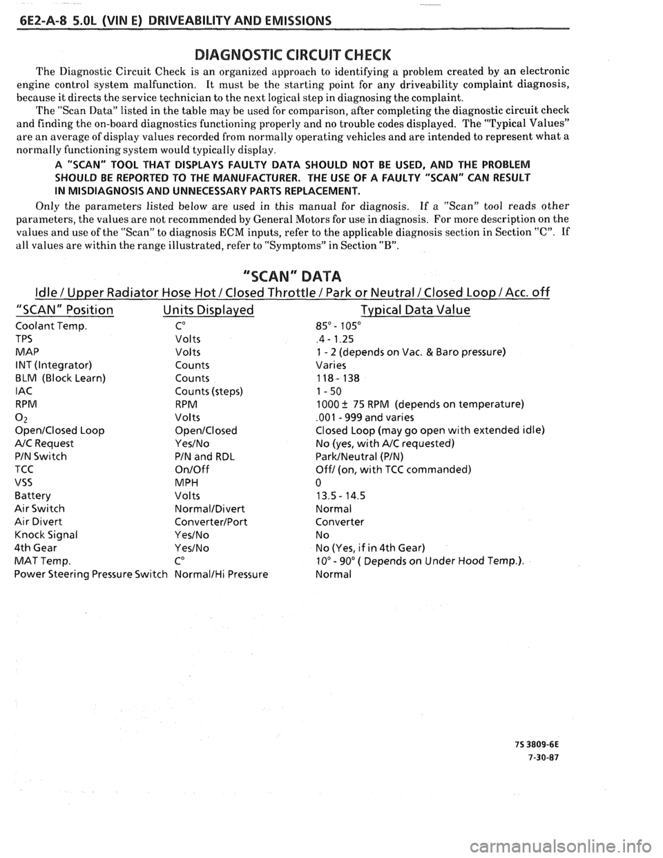
The "Scan Data" listed in the table may be used for comparison, after completing the diagnostic circuit check
and finding the on-board diagnostics functioning properly and no trouble codes displayed. The "Typical Values"
are an average of display values recorded from normally operating vehicles and are intended to represent what a
normally functioning system would typically display.
A "SCAN" TOOL THAT DISPLAYS FAULTY DATA SHOULD NOT BE USED, AND THE PROBLEM
SHOULD BE REPORTED TO THE MANUFACTURER. THE USE OF A FAULTY "SCAN" CAN RESULT
IN MISDIAGNOSIS AND UNNECESSARY PARTS REPLACEMENT.
Only the parameters listed below are used in this manual for diagnosis. If
a "Scan" tool reads other
parameters, the values are not recommended by General Motors for use in diagnosis. For more description on the
values and use of the "Scan" to diagnosis ECM inputs, refer to the applicable diagnosis section in Section
"C". If
all values are within the range illustrated, refer to "Symptoms" in Section
"B".
""SCAN" DATA
Idle / Upper Radiator Hose Hot / Closed Throttle / Park or Neutral /Closed Loop / Acc. off
"SCAN" Position Units Displayed Typical
Data Value
Coolant Temp. CO 85" - 105"
TPS Volts .4 - 1.25
MAP Volts
1 - 2 (depends on Vac. & Baro pressure)
INT (Integrator) Counts Varies
BLM (Block Learn) Counts 118- 138
IAC Counts (steps) 1-50
RPM RPM 1000
k 75 RPM (depends on temperature)
0 2 Volts .001 - 999 and varies
OpenIClosed Loop OpenICIosed Closed Loop (may go open with extended idle)
A/C Request YesINo No (yes, with A/C requested)
PIN Switch PIN and RDL
ParkINeutral (PIN)
TCC
On/Off Off1 (on, with TCC commanded)
VSS MPH 0
Battery Volts 13.5- 14.5
Air Switch NormalIDivert Normal
Air Divert ConverterIPort Converter
Knock Signal
YesINo N o
4th Gear
YesINo No (Yes, if in 4th Gear)
MAT Temp.
CO 10" - 90" ( Depends on Under Hood Temp.).
Power Steering Pressure Switch
NormalIHi Pressure Normal
Page 560 of 1825
DRIVEABILITY AND EMISSIONS 5.OL (VIN E) 6EZ-C1-5
DIAGNOSIS
Since the ECM can have a failure which may
effect only one circuit, following the diagnostic
procedures in this section can reliably tell when a
failure has occurred in the ECM. Also,
a Code
55 in
dicates a failure of the ECM.
If a diagnostic chart indicates that the ECM
connections or ECM is the cause of a
problem,and the
ECM is replaced, but does not correct the problem, one
of the following may be the reason:
e
connections. - The diagnostic chart will say "ECM
Connections or ECM". The terminals mav have to be
removed from the connector in order to check them
properly.
@ The ECM or PROM is not correct for the
. - The incorrect ECM or PROM may cause
a malfunction and may or may not set a code.
. - This means that
time the system is
being checked. In this case, refer to the "Symptoms"
portion of the manual and make a careful physical
Solenoids and relays are turned "ON" and "OFF" by
the ECM, using internal electronic switches called
"Drivers".
A shorted solenoid, relay coil, or harness in a
GMP4 computer will not damage the ECM,
but will cause the circuit and controlled
component to be inoperative. When the
circuit fault is not present or has been
repaired, the "Quad-Driver" will again
operate in a normal manner due to it's fault
protected design. If a fault has been repaired
in a circuit controlled
by a "Quad-Driver", the
original
ECM should be reinstalled and the
circuit checked for proper operation.
ECM
replacement will not be necessary if the
repaired circuit or component now operates
correctly.
534636 or BT8405 testers or equivalent provide a
fast, accurate means of checking for a shorted coil or a
short to battery voltage.
e , - Although the
PROM rarely
fails,it operates as part of the ECM.
Therefore, it could be the cause of the problem.
Substitute a known good PROM.
o . - After the
ECM is replaced, the system should be rechecked for
proper operation. If the diagnostic chart again
indicates the ECM is the problem, substitute a known
good ECM. Although this is a rare condition, it could
happen. The
components or circuits and the codes or
charts, related to them are:
@ Code 55 indicates a failure of the ECM.
@ PROM - Code 51.
@ Coolant Temperature Sensor - CHARTS 14 -
15.
@ MAP sensor - CHART 33 or 34. To check the
sensor with no code set, use CHART
C-1D.
e TPS - CHARTS 21 or 22.
e PIN switch - CHART C-1A
@ Crank Signal - CHART C-1B
@ O2 Sensor - CHARTS 13,44,45.
@ VSS - CHART 24 and in TCC System.
e Distributor - CHART 42 and in EST system.
@ Distributor - Chart and in the EST system.
ECM
A faulty ECM will be determined in the diagnostic
charts, or by a Code 55.
PROM
An incorrect or faulty PROM, which is part of the
ECM, may set a Code 51.
ECM INPUTS
All of the sensors and input switches can be
diagnosed by the use of a "Scan" tool. Following is
a
short description of how the sensors and switches can
be diagnosed by the use of "a Scan" tool. The
"Scan"
tool can also by used to compare the values for a
normal running engine with the engine you're
diagnosing.
Coolant Temperature Sensor
A "Scan" tool displays engine temp. in degrees
centigrade. After the engine is started, the
temperature should rise steadily to about
90°C, then
stabilize when thermostat opens.
A fault in the
coolant sensor circuit should set a Code 14 or 15. The
code charts also contain a chart to check for sensor
resistance values relative to temperature.
MAT Sensor
A "Scan" tool displays temperature of the air
entering the engine and should read close ambient air
temperature, when engine is cold, and rise
as
underhood temperature increases. If the engine has
not been run for several hours (overnight), the MAT
sensor temperature and coolant temperature should
read close to each other.