1988 PONTIAC FIERO gas type
[x] Cancel search: gas typePage 421 of 1825
6B-10 ENGINE COOLING
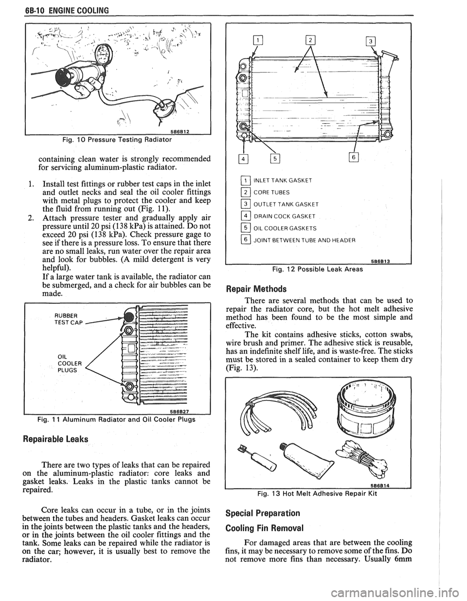
Fig. 10 Pressure Testing Radiator
containing clean water is strongly recommended
for servicing aluminum-plastic radiator.
I. Install test fittings or rubber test caps in the inlet
and outlet necks and seal the oil cooler fittings
with metal plugs to protect the cooler and keep
the fluid from running out (Fig.
11).
2. Attach pressure tester and gradually apply air
pressure until 20 psi (1
38 kPa) is attained. Do not
exceed 20 psi (138
kPa). Check pressure gage to
see if there is a pressure loss. To ensure that there
are no small leaks, run water over the repair area
and look for bubbles.
(A mild detergent is very
helpful).
If a large water tank is available, the radiator can
be submerged, and a check for air bubbles can be
made.
Fig. I I Aluminum Radiator and Oil Cooler Plugs
Repairable Leaks
There are two types of leaks that can be repaired
on the aluminum-plastic radiator: core leaks and
gasket leaks. Leaks in the plastic tanks cannot be
repaired.
L1_] INLET TANK GASKET
11_] CORE TUBES
OUTLET TANK GASKET
DRAIN COCK GASKET
OIL COOLER GASKETS
JOINT BETWEEN TUBE AND HEADER
Fig. 12 Possible Leak Areas
Repair Methods
There are several methods that can be used to
repair the radiator core, but the hot melt adhesive
method has been found to be the most simple and
effective.
The kit contains adhesive sticks, cotton swabs,
wire brush and primer. The adhesive stick is reusable,
has an indefinite shelf life, and is waste-free. The sticks
must be stored in a sealed container to keep them dry
(Fig. 13).
Fig. 13 Hot Melt Adhesive Repair Kit
Core leaks can occur in a tube, or in the joints special preparation between the tubes and headers. Gasket leaks can occur
in the joints between the plastic tanks and the headers,
cooling Fin Removal or in the joints between the oil cooler fittings and the
tank. Some leaks can be repaired while the radiator is For
damaged areas that are between the cooling
on the car; however, it is usually best to remove the fins,
it may be necessary to remove some of the fins. Do
radiator. not remove more fins
than necessary. Usually
6mm
Page 423 of 1825
88-12 ENGINE COOLING
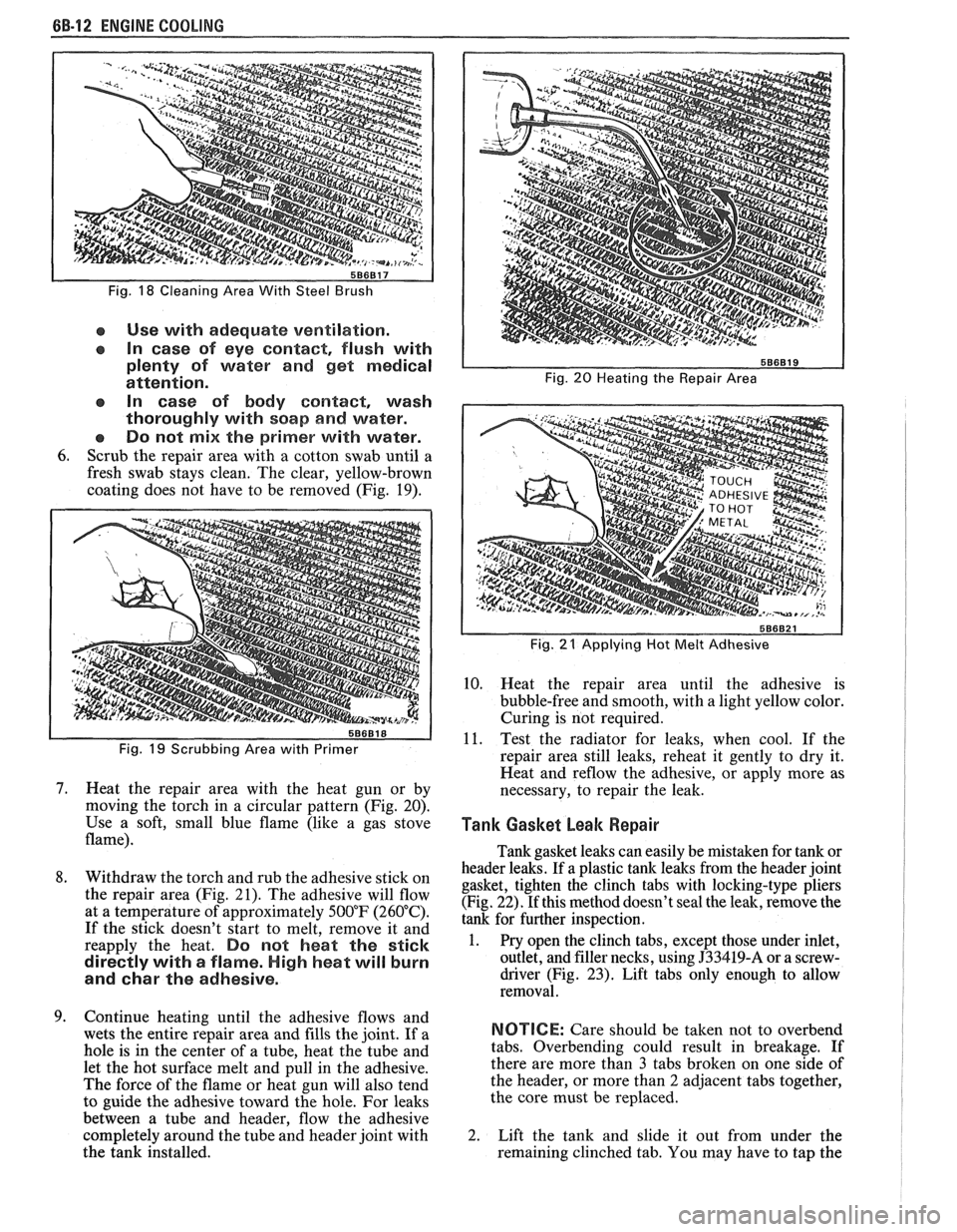
Fig. 18 Cleaning Area With Steel Brush
e Use with adequate ventilation.
In case of eye contact, flush with
plenty of water and get medical
attention.
In case of body
contact, wash
thoroughly with soap
and water.
Do not
mix the primer with water.
6. Scrub the repair area with a cotton swab until a
fresh swab stays clean. The clear, yellow-brown
coating does not have to be removed (Fig. 19).
Fig. 19 Scrubbing Area with Primer
7. Heat the repair area with the heat gun or by
moving the torch in a circular pattern (Fig. 20).
Use a soft, small blue flame (like a gas stove
flame).
8. Withdraw the torch and rub the adhesive stick on
the repair area (Fig. 21). The adhesive will flow
at a temperature of approximately 500°F (260°C).
If the stick doesn't start to melt, remove it and
reapply the heat.
Do not heat the stick
directly with
a flame. High heat will burn
and
char the adhesive.
9. Continue heating until the adhesive flows and
wets the entire repair area and fills the joint. If a
hole is in the center of a tube, heat the tube and
let the hot surface melt and pull in the adhesive.
The force of the flame or heat gun will also tend
to guide the adhesive toward the hole. For leaks
between a tube and header, flow the adhesive
completely around the tube and header joint with
the tank installed.
Fig. 20 Heating the Repair Area
I
Fig. 21 Applying Hot Melt Adhesive I
10. Heat the repair area until the adhesive is
bubble-free and smooth, with a light yellow color.
Curing is not required.
11. Test the radiator for leaks, when cool. If the
repair area still leaks, reheat it gently to dry it.
Heat and
reflow the adhesive, or apply more as
necessary, to repair the leak.
Tank Gasket beak Repair I 1
Tank gasket leaks can easily be mistaken for tank or
header leaks. If a plastic tank leaks from the header joint
gasket, tighten the clinch tabs with locking-type pliers
(Fig. 22). If this method doesn't seal the leak, remove the
tank for further inspection.
1. Pry open the clinch tabs, except those under inlet,
outlet, and filler necks, using
J33419-A or a screw-
driver (Fig.
23). Lift tabs only enough to allow
removal.
NOTICE: Care should be taken not to overbend
tabs. Overbending could result in breakage. If
there are more than
3 tabs broken on one side of
the header, or more than
2 adjacent tabs together,
the core must be replaced.
2. Lift the tank and slide it out from under the
remaining clinched tab. You may have to tap the
Page 432 of 1825
ENGINE FUEL BC-1
SECTION 6C
NE FUEL
CONTENTS
General Description ..................................... 6C-1 Fuel
Cap ........................................................... 6C-3
.................................................. ............................................. Alcohol-In-Fuel 6C- 1 Fuel Filter Neck 6C-3
................... ............ Fuel Metering .................................................. 6C-2 Fuel Gage Sending Unit .. 6C-4
....................... ............................... Throttle Body Injection (TBI) .... 6C-2 Diagnosis ,. 6C-4 ................... Service
Procedures ............................................. 6C-4
Port Fuel Injection ...................................... 6C-2
Pressure Relief ........................................... 6C-4
Fuel Feed and Return Pipe
............................... 6C-2
Flow Test .................................................... 6C-4
Fuel Pipes (MPFI)
.......................................... 6C-3
Pressure Test - TBI ................................... 6C-4
Fuel and Vapor Hoses
....................................... 6C-3
Pressure Test - MPFI .................................... 6C-4
Fuel Pump ........................................................ 6C-3 ...................................................... Fuel Pump Relay .............................................. 6C-3 Fuel Tank 6C-4
Fuel Filter
......................................................... 6C-3 Accelerator Controls ...................................... 6C-5
Fuel Tank
....................................................... 6C-3
All new General Motors vehicles are certified by
the United States Environmental Protection Agency as
conforming to the requirements of the regulations for
the control of air pollution from new motor vehicles.
This certification is contingent on certain adjustments
being set to factory standards. In most cases, these
adjustment points either have been permanently
sealed and/or made inaccessible to prevent
indiscriminate or routine adjustment in the field. For
this reason, the factory procedure for temporarily
removing plugs, caps, etc., for purposes of servicing the
product must be strictly followed and, wherever
practicable, returned to the original intent of the
design.
GENERAL DESCRIPTION
All gasoline engines are designed to use only
unleaded gasoline. Unleaded gasoline must be used for
proper emission control system operation. Its use will
also minimize spark plug fouling and extend engine oil
life. Using leaded gasoline can damage the emission
control system and could result in loss of emission
warranty coverage.
All cars are equipped with an Evaporative
Emission System. The purpose of the system is to
minimize the escape of fuel vapors to the atmosphere.
Information on this system will be found in Section
6E2, or 6E3.
When working on the fuel system, there are
several things to keep in mind.
@ Any time fuel system is being worked on,
disconnect the negative battery cable
except for those tests where battery
Adhere to all Notices and Cautions.
Always keep a dry chemical (Class B) fire
extinguisher near the work area.
-
Always use a backup wrench when loosening or
tightening a screw couple fitting.
The torque on a screw fitting is
30 N-m (22 lb.
ft.).
Pipe is used on all MPFI, TPI, SFI, and TBI
applications. Fittings require the use of an
"0"
Ring. Replace all pipe with the same type of pipe
and fittings that were removed.
All fuel pipes must meet GM Specification
124-M, or its equivalent.
All fuel hoses must meet GM Specification
6163-M, or its equivalent.
Do not replace fuel pipe with fuel hose.
voltage is required.
@ On MPFI, TPI, SF1 and TBI systems, always A1cohol-ln-Fuel
relieve the line pressure before servicing any fuel Certain driveability complaints such as
system components. hesitation, lack of power, stall, no start, etc., may be
@ Do not repair the fuel system until you have read caused
by an excessive amount of alcohol-in-fuel. The
the copy and checked the illustrations relating to complaints
may be due to fuel system corrosion and
that repair. subsequent
fuel filter plugging, deterioration of rubber
Page 433 of 1825

6C-2 ENGINE FUEL
components such as the accelerator pumps and/or
air-fuel mixture leaning effects.
Various types and concentrations of alcohols are
used in commercial gasoline. Some alcohols are more
detrimental to fuel system components than others. If
an excessive amount of alcohol in the fuel is suspected
as the cause of a driveability condition, the following
procedure may be used to detect the presence of
alcohol in the fuel.
In this procedure, water is used to
extract the alcohol from the fuel. However, the specific
type of alcohol is not determined.
The fuel sample should be drawn from the
bottom part of the tank so that any water, if already
present, can be detected. The sample should be bright
and clear. If the sample appears cloudy or
contaminated with water as indicated by a water layer
in the bottom part of the sample, this procedure should
not be used. The fuel system should then be cleaned
(See Fuel System Cleaning).
Testing Procedure
1. Using a 100 ml cylinder with 1 ml graduation
marks, fill with fuel to the 90 ml mark.
2. Add 10 ml of water to bring the total fluid volume
to 100 ml and install a stopper.
3. Shake vigorously for 10 to 15 seconds.
4. Carefully loosen stopper to release pressure.
5. Close the stopper and shake vigorously again for
10 to 15 seconds.
6. Carefully loosen
stopper to release pressure.
7. Put the graduated cylinder on a level surface for
approximately 5 minutes to allow adequate liquid
separation.
If alcohol is present in the fuel, the volume of the
lower layer, which would now contain alcohol and
water will be greater than 10 ml. For example, if the
volume of the lower layer is increased to 15 ml, it
would indicate at least 5 percent alcohol in fuel. The
actual amount of alcohol may be somewhat greater
because this procedure does not extract all of the
alcohol from the fuel.
FUEL METERING
Throttle Body lnjection
(TBI)
With Throttle Body Injection (TBI), an injection
unit is placed on the intake manifold where the
carburetor is normally mounted. The TBI unit is
computer controlled and supplies the correct amount
of fuel during all engine operating conditions. See
Section 6E2 for information relative to operation and
diagnosis of TBI units.
Port Fuel lnjection
The ECM is in complete control of this fuel
delivery system during all driving conditions.
The intake manifold is used only to let air into the
engine. Fuel is injected by separate injectors that are
mounted over the intake valve.
With the Port Injection System, there is no need
for a Thermac, EFE, Map Sensor, Baro Sensor, A.I.R.
System, or Dual Bed Converter. This
system provides better cold driveability,
lower exhaust emissions and better throttle response.
In Sequential Fuel Injection systems (SFI),
injectors turn on at every crankshaft revolution. The
ECM controls the injector "on" time so that the
correct amount of fuel is metered, depending on
driving conditions.
Two interchangeable
"0" rings are used on the
injector that must be inspected when the injectors are
removed. Check
"0" rings for cuts or other type of
damage and replace as necessary.
The air cleaner is remotely mounted near the
radiator. It is connected to the intake manifold by air
intake ducting.
Also, mounted between the air cleaner and
intake, are the mass air flow sensor and throttle body.
Cold driveability characteristics are greatly
improved with the aid of an engine coolant supply to
the throttle body for rapid warm up.
The throttle body design uses an integral Idle Air
Control to govern idle speed and a Throttle Position
Sensor (TPS). The IAC and TPS are both controlled
by the ECM.
A large diameter fuel rail is attached to the intake
manifold and supplies fuel to all the injectors.
A fuel pressure tap is located on the rail for quick
pressure checks.
Fuel is recirculated through the rail continually
while the engine is running. This removes air and
vapors from the fuel as well as keeping the fuel cool
during hot weather operation.
A fuel pressure regulator is mounted on the fuel
rail. It maintains a constant 36 psi pressure across the
injectors under all operating conditions. It is
accomplished by controlling the amount of fuel that is
recirculated back to the fuel tank, based on engine
demand.
The pressure regulator also uses an
"0" ring for
attachment. The
"0" ring used is the same one that is
used for the injectors.
Some engines also have an accumulator that is
located in the fuel feed line near the cowl area. It is used
to dampen the vibration that is caused by the
pressurized fuel and the pulsing of the injector.
See Section 6E3 for more information and
diagnosis.
Fuel Feed and Return Pipe
When replacing fuel feed and return pipes, always
replace them with welded steel tubing meeting GM
Specification
124M, or its equivalent. The replacement
pipe must use the same type of fittings as the original
pipes to ensure the integrity of the connection.
NOTICE: Do not replace fuel pipe with fuel hose
or any other type of tubing such as copper or
aluminum. Only tubing meeting the 124M
specification is capable of meeting all the pressure
and vibration characteristics necessary to ensure
the durability standard required.
Always check and replace any
"0" rings or
washers that appear damaged.
Page 434 of 1825
ENGINE FUEL 6C.3
a Fuel feed and return pipes are secured to the
underbody with clamps and screw assemblies.
The pipes should be inspected occasionally for
leaks, kinks or dents.
e Follow the same routing as the original pipe.
e Pipes must be properly secured to the frame to
prevent chafing. A minimum of 6 mm
(1/4")
clearance must be maintained around a pipe to
prevent contact and chafing.
MPFl Fuel Pipes
Due to the fact that fuel pipes are under high
pressure, these systems require special consideration for service.
Many feed and return pipes use screw couplings
with
"0" Rings. Any time these fittings are loosened
to service or replace components, ensure that:
a A backup wrench is used while loosening and
tightening the fitting.
e Check all "0" rings at fitting locations (if
applicable) for cuts or any damage and replace
any that appear worn or damaged.
e Use correct torque when tightening fittings.
If pipes are replaced always use original
equipment parts, or parts that meet GM
specifications.
Fuel and Vapor Hoses
NOTICE: Fuel and vapor hoses are specially
manufactured. If replacement becomes necessary,
it is important to use only replacement hoses
meeting GM Specification 6163-M. These hoses
are identified with the words "Fluoroelastomer"
on them. Hoses not so marked could cause early
failure, or fail to meet emission standards.
e Do not use rubber hose within 4" of any part of
the exhaust system, or within
10" of the catalytic
converter.
FUEL PUMP
The electric fuel pump is in the fuel tank. The
tank has an outlet for a vapor return system. Any vapor
which forms is returned to the fuel tank along with hot
fuel through a separate line. This greatly reduces any
possibility of vapor lock by keeping cool fuel from the
tank constantly circulating through the fuel pump.
FUEL PUMP RELAY
To control fuel pump operation, a fuel pump
relay is used.
When the ignition switch is turned to "RUN"
position, the fuel pump relay activates the electric fuel
pump for
1.5 to 2.0 seconds to prime the injector(s). If
the ECM does not receive reference pulses from the
distributor after this time, the ECM signals the relay
to turn off the fuel pump. The relay will once again
activate the fuel pump when the
ECM receives
distributor reference pulses.
Fuel Filter
CAUTION: To reduce the risk of fire
and personal injury, it is necessary
to
relieve the fuel system pressure
before servicing fuel system
components. (See Fuel System
Pressure Relief.)
The inline filters can be found on the rear
crossmember of the vehicle. Always use a backup
wrench any time that the fuel filter is removed or
installed. Also make sure that a good
"0" Ring is used
at all screw couple locations. Torque on fittings is
30
N-m (22 lb. ft.).
FUEL TANK
The fuel tank is usually located under the rear of
the vehicle and a number of shapes and sizes are used
depending on the application.
The tank is held in place by two metal straps,
hinged (with a bolt through the hinge) and secured at
the opposite end with a nut and bolt assembly.
Anti-squeak pieces are used on top of the tank to
reduce rattles and other annoying noises.
The fuel tank, cap and lines should be inspected
for road damage, whch could cause leakage. Inspect
fuel cap for correct sealing and indications of physical
damage. Replace any damaged or malfunctioning
parts.
Before attempting service of any type on the fuel
tank, always
(1) remove negative battery cable from
battery, (2) place "no smoking" signs near work areas,
(3) be sure to have C02 fire extinguisher handy, (4)
wear safety glasses and
(5) siphon or pump fuel into an
explosion proof container.
Fuel Filler Gap
The fuel tank filler neck is equipped with a
screw-type cap. The threaded part of the cap requires
several turns counterclockwise to remove. The long
threaded area is designed to allow any remaining fuel
tank pressure to escape while the cap is being removed.
A built-in torque-limiting device prevents
overtightening. To install, turn the cap clockwise until
a clicking noise is heard. This signals that the correct
torque has been reached and the cap is fully seated.
N OTI G E: If a fuel filler cap requires replacement,
use only a cap with the same features. Failure to
use the correct cap can result in a serious
malfunction of the system.
Available on some models is an electric locking
fuel filler cap. Information on this option will be found
in Section
9E.
FUEL TANK FILLER NECK
To help prevent refueling with leaded gasoline,
the fuel filler neck on gasoline engine cars has a built-in
restrictor and deflector. The opening in the restrictor
will only admit the smaller unleaded gas nozzle spout,
which must be fully inserted to bypass the deflector.
Attempted refueling with a leaded gas nozzle or failure
Page 446 of 1825
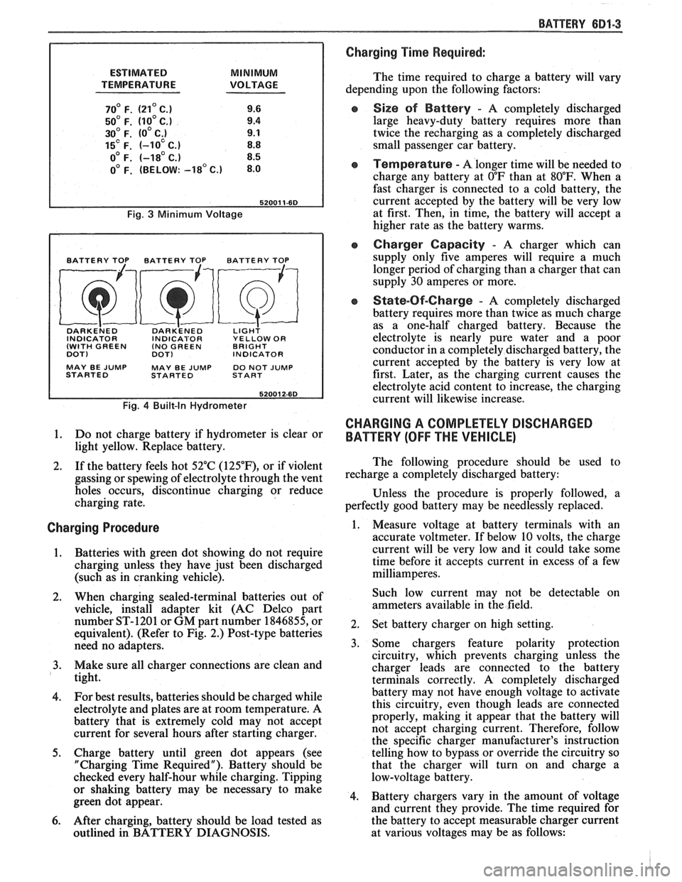
ESTIMATED MINIMUM
TEMPERATURE VOLTAGE
70' F. (21' C.) 9.6
50' F. (10' C.) 9.4
30' F. (0' C;) 9.1
15' F. (-10 C.) 8.8
o0 F. (-18' C.) 8.5
0' F. (BELOW: -18' c.) 8.0
Fig. 3 Minimum Voltage
BATTERY TOP BATTERY TOP BATTERY TOP
DARKE~ED DARK'ENED LIGH? INDICATOR INDICABOR YELLOW OR
(WITH GREEN (NO
GREEN BRIGHT
DOT)
DOT) INDICATOR
MAY BE
JUMP MAY BE JUMP DO NOT JUMP
STARTED STARTED START
Fig. 4 Built-In Hydrometer
1. Do not charge battery if hydrometer is clear or
light yellow. Replace battery.
2. If the battery feels hot 52°C
(125"F), or if violent
gassing or spewing of electrolyte through the vent
holes occurs, discontinue charging or reduce
charging rate.
Charging Procedure
1. Batteries with green
dot showing do not require
charging unless they have just been discharged
(such as in cranking vehicle).
2. When charging sealed-terminal batteries out of
vehicle, install adapter kit (AC Delco part
number ST-1201 or GM part number 1846855, or
equivalent). (Refer to Fig. 2.) Post-type batteries
need no adapters.
3. Make sure all charger connections are clean and
tight.
4. For
best results, batteries should be charged while
electrolyte and plates are at room temperature. A
battery that is extremely cold may not accept
current for several hours after starting charger.
5. Charge battery until green dot appears (see
"Charging Time Required"). Battery should be
checked every half-hour while charging. Tipping
or shaking battery may be necessary to make
green dot appear.
6. After charging, battery should be load tested as
outlined in BATTERY DIAGNOSIS.
BATTERY 681-3
Charging Time Required:
The time required to charge a battery will vary
depending upon the following factors:
e Size sf Battery - A completely discharged
large heavy-duty battery requires more than
twice the recharging as a completely discharged
small passenger car battery.
Temperature - A longer time will be needed to
charge any battery at
O"F than at 80°F. When a
fast charger is connected to a cold battery, the
current accepted by the battery will be very low
at first. Then, in time, the battery will accept a
higher rate as the battery warms.
Charger Capacity - A charger which can
supply only five amperes will require a much
longer period of charging than a charger that can
supply
30 amperes or more.
e State-Of-Charge - A completely discharged
battery requires more than twice as much charge
as a one-half charged battery. Because the
electrolyte is nearly pure water and a poor
conductor in a completely discharged battery, the
current accepted by the battery is very low at
first. Later, as the charging current causes the
electrolyte acid content to increase, the charging
current will likewise increase.
CHARGING A COMPLETELY DISCHARGED
BATTERY
(OFF THE VEHICLE)
The following procedure should be used to
recharge a completely discharged battery:
Unless the procedure is properly followed, a
perfectly good battery may be needlessly replaced.
1. Measure voltage at battery terminals with an
accurate voltmeter. If below 10 volts, the charge
current will be very low and it could take some
time before it accepts current in excess of a few
milliamperes.
Such low current may not be detectable on
ammeters available in the field.
2. Set battery charger on high setting.
3. Some chargers feature polarity protection
circuitry, which prevents charging unless the
charger leads are connected to the battery
terminals correctly. A completely discharged
battery may not have enough voltage to activate
this circuitry, even though leads are connected
properly, making it appear that the battery will
not accept charging current. Therefore, follow
the specific charger manufacturer's instruction
telling how to bypass or override the circuitry so
that the charger will turn on and charge a
low-voltage battery.
4. Battery chargers vary in the amount of voltage
and current they provide. The time required for
the battery to accept measurable charger current
at various voltages may be as follows:
Page 470 of 1825
IGNITION SYSTEM 6D4-1
ON SYSTEM
CONTENTS
General Description ............................... 6D4-1 Service Procedures ............................. 6D4-3
Ignition System .......................................... 6D4-1
Ignition System .......................................... 6D4-3
Distributor Ignition ................................ 6D4-1
Distributor Ignition ................................ 6D4 -3
Diannosis .................................................... 6D4-3 On-Car Service ......................................... 6D4-5 -
Ignition System .......................................... (334-3 Ignition System ........................... .. .............. 6D4-5
Distributor ................................................. 6D4 -7 HE1 Distributor .................................... 6D4-3
GENERAL DESCRIPION
The engine electrical system includes the battery,
ignition (primary and secondary), starter (and related
wiring) and the generator (and related wiring).
Diagnostic charts (see Section 6D) will aid in
trouble-shooting system faults. When a fault is traced
to a particular component, refer to that components'
section of the service manual.
IGNITION SYSTEM
Distributor Ignition
The ignition circuit consists of the battery,
distributor, ignition switch, spark plugs and primary
and secondary wiring. Refer to the Battery portion of
this section for battery information.
PIE1 Distributor
The Nigh Energy Ignition (HEI) distributor with
Electronic Spark Timing (EST), used on most engines,
combines all ignition components in one unit. The
ignition coil is in the distributor cap and connects
through a resistance brush to the rotor.
The distributor has an internal magnetic pick-up
assembly which contains a permanent magnet, a pole
piece with internal teeth and a pick-up coil. When the
teeth of the timer core, rotating inside the pole piece,
line up with the teeth of the pole piece, an induced
voltage in the pick-up coil signals the electronic module
to trigger the coil primary circuit. The primary current
decreases and a high voltage is induced in the ignition
coil secondary winding. This voltage is directed
through the rotor and secondary leads to fire the spark
plugs. The capacitor in the distributor is for radio noise
suppression,
All spark timing changes in the
HE1 (EST)
distributor are done electronically by an Electronic
Control Module (ECM), which monitors information
from various engine sensors, computes the desired
spark timing and signals the distributor to change the
timing accordingly.
A back-up spark advance system
is incorporated to signal the ignition module in case of
(ECM) failure. No vacuum or mechanical advance is
used. Further (EST) information is found in sections 6E
Emissions Control, and
8A Electrical
Troubleshooting.
Ignition Timing
Timing specifications for each engine are listed in
Section
6E. When using a timing light, connect an
adapter between the No. 1 spark plug and the No. 1
spark plug wire, or use an inductive type pick-up.
Do
not pierce the plug lead.
Once the insulation of the
spark plug cable has been broken, voltage will jump to
the nearest ground, and the spark plug will not fire
properly.
Always follow the tune-up label
procedures when adjusting timing.
Some engines will incorporate a magnetic timing
probe hole for use with special electronic timing
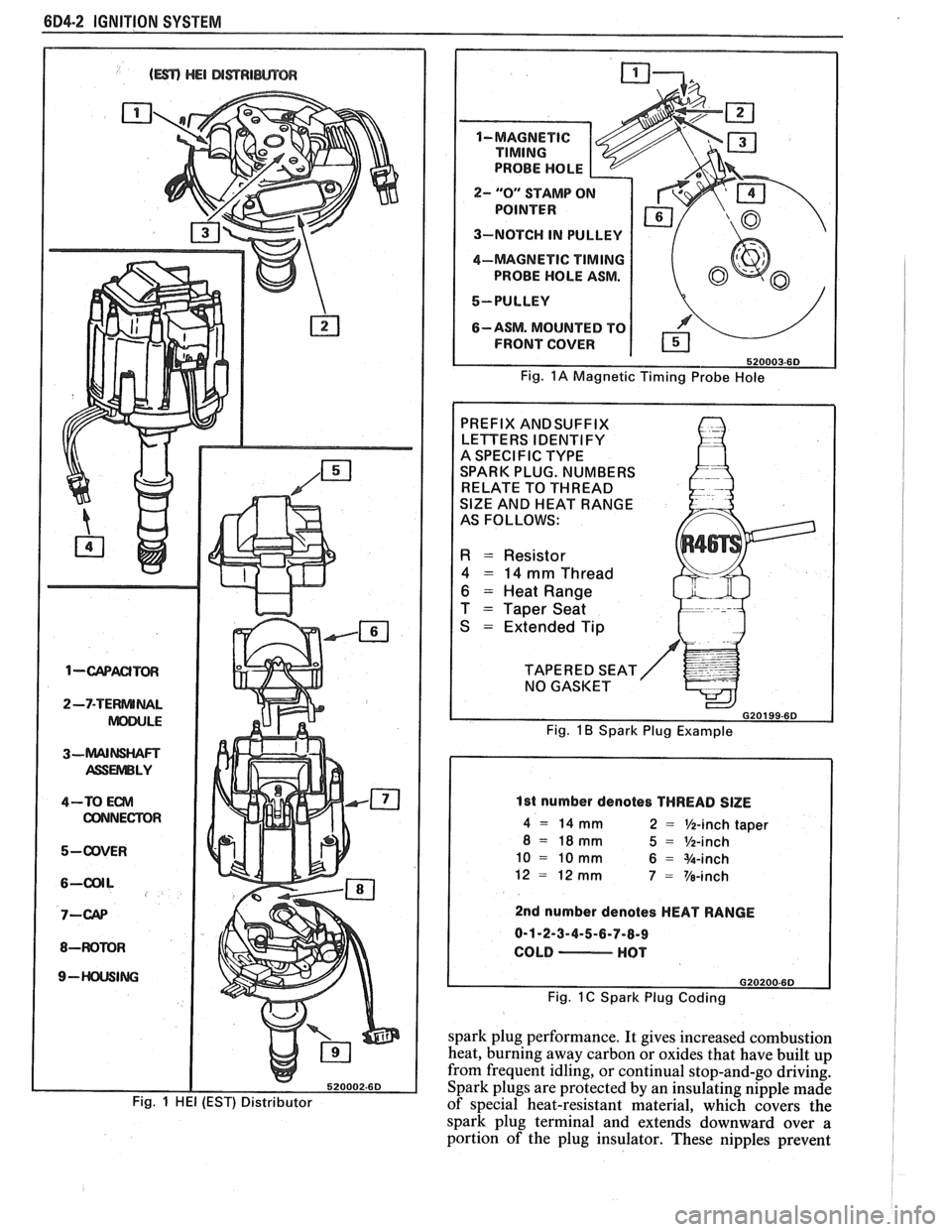
equipment. Fig.
1A shows a typical magnetic probe
hole. Consult manufacturer's instructions for use of
this equipment.
Secondary Wiring
The spark plug wiring used with ignition systems
is a carbon impregnated cord conductor, encased in an
8MM (5/16") diameter silicone rubber jacket. The
silicone jacket withstands very high temperatures and
also provides an excellent insulator for the higher
voltage of the
HE1 system. Silicone spark plug boots
form a tight seal on the plug.
The boot should be
twisted 1/2 turn before removing. Care should
also be exercised when connecting a timing light or
other pick-up equipment. Do not force anything
between the boot and wiring, or through the silicone
jacket. Connections should be made in parallel using
an adapter. DO NOT pull on the wire to remove. Pull
on the boot, or use a tool designed for this purpose.
Spark Plugs
Resistor type, tapered seat spark plugs are used
on all engines (except aluminum heads). No gasket is
used on these tapered seat plugs. See Figs.
1B and 1C
for an explanation of coding on spark plugs.
Normal service is assumed to be a mixture of
idling, slow speed, and high speed driving. Occasional
or intermittent high-speed driving is needed for good
Page 471 of 1825
604-2 IGNITION SYSTEM
1-wACITm
2-7-TERNUNAL
ASSUVlBLY
4-TO Em
CONNECTOR
5-ODVER
8-WOMR
9- ING
Fig. 1 HE1 (EST) Distributor
2- "0" STAMP O
3-NOTCH IN PULLEY
4-MAGNETIC
TIMING
PROBE HOLE ASM.
5-PULLEY
6-ASM. MOUNTED TO
FRONT COVER
Fig. 1A Magnetic Timing Probe Hole
PREFIX ANDSUFFIX
LETTERS IDENTIFY
A SPECIFIC TYPE
SPARK PLUG. NUMBERS
RELATE TO THREAD
SlZE AND HEAT RANGE
AS FOLLOWS:
R = Resistor
4 = 14 mm Thread
6 = Heat Range
T
= Taper Seat
S
= Extended Tip
TAPERED SEAT NO GASKET
G20199-6D
Fig. 1 B Spark Plug Example
1st number denotes THREAD SlZE
4 = 14 mm 2 = %-inch taper
8 = 18mm 5 = %-inch
10 = 10 mm 6 = %-inch
12
= 12 mm 7 = Ve-inch
2nd number denotes HEAT RANGE
0-1-2-3-4-5-6-7-8-9
COLD
- HOT
Fig. 1 C Spark Plug Coding
spark plug performance. It gives increased combustion
heat, burning away carbon or oxides that have built up
from frequent idling, or continual stop-and-go driving.
Spark plugs are protected by an insulating nipple made
of special heat-resistant material, which covers the
spark plug terminal and extends downward over
a
portion of the plug insulator. These nipples prevent