1988 PONTIAC FIERO gas type
[x] Cancel search: gas typePage 1728 of 1825

DOORS - F STYLE 51.1-15
REAR GUIDE CHANNEL
Removal and lnstallation
1. Raise glass to half-up position.
2. Remove door trim panel and water deflector.
3. Remove three attaching bolts to loosen channel
from inner panel.
4. While pulling channel up and back, rotate
channel
180 degrees and remove from sash roller
(Fig.
32).
5. Remove rear guide channel through rear access
hole.
6. To install, reverse the removal procedure.
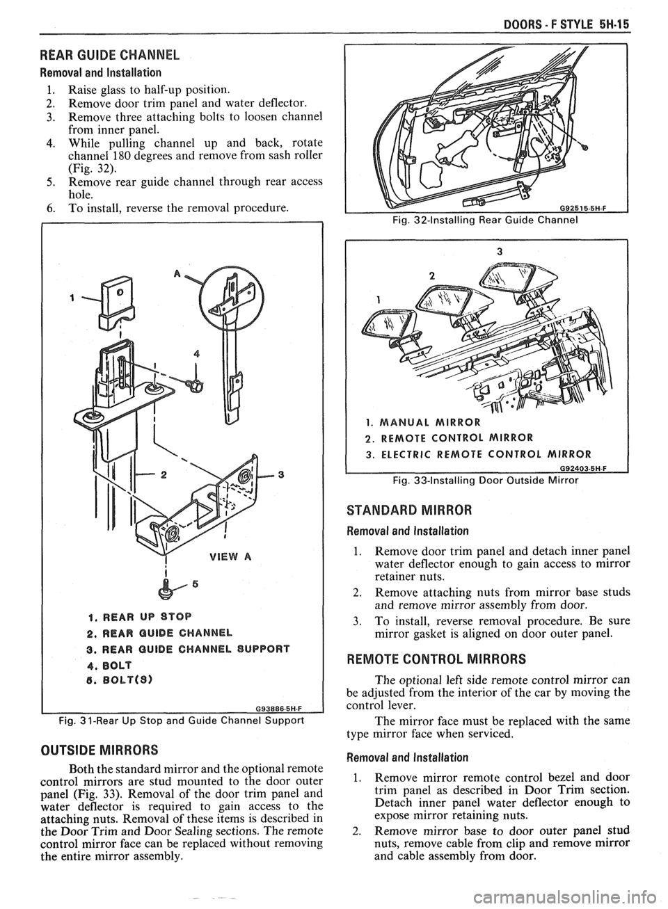
1, REAR UP STOP
2. REAR QUlDE CHANNEL
3. REAR GUIDE CHANNEL SUPPORT
4, BOLT
6. BObP(S)
Fig. 3 ?-Rear Up Stop and Guide Channel Support
OUTSIDE MIRRORS
Both the standard mirror and the optional remote
control mirrors are stud mounted to the door outer
panel (Fig.
33). Removal of the door trim panel and
water deflector is required to gain access to the
attaching nuts. Removal of these items is described in
the Door Trim and Door Sealing sections. The remote
control mirror face can be replaced without removing
the entire mirror assembly.
Fig. 32-Installing Rear Guide Channel
1. MANUAL MIRROR
2. REMOTE CONTROL MIRROR
3. ELECTRIC REMOTE CONTROL MIRROR
G92403-5H-F
Fig. 33-Installing Door Outside Mirror
STANDARD MIRROR
Removal and Installation
1. Remove door trim panel and detach inner panel
water deflector enough to gain access to mirror
retainer nuts.
2. Remove attaching nuts from mirror base studs
and remove mirror assembly from door.
3. To install, reverse removal procedure. Be sure
mirror gasket is aligned on door outer panel.
REMOTE CONTROL MIRRORS
The optional left side remote control mirror can
be adjusted from the interior of the car by moving the
control lever.
The mirror face must be replaced with the same
type mirror face when serviced.
Removal and Installation
1. Remove mirror remote control bezel and door
trim panel as described in Door Trim section.
Detach inner panel water deflector enough to
expose mirror retaining nuts.
-
2. Remove mirror base to door outer panel stud
nuts, remove cable from clip and remove mirror
and cable assembly from door.
Page 1744 of 1825

REAR END - F STYLE 7H-1
SECTION 7H
REAR END
NOTICE: The anti-theft label found on some major sheet metal, engines, and transmissions must be masked
prior to painting, rustproofing, undercoating, etc. The mask
must be removed following the above operations.
Failure to keep the label clean and readable may result in liability for violation of Federal Vehicle Theft Prevention
Standard, and subject the vehicle owner to possible suspicion that the part was stolen.
CONTENTS
Moldings, Emblems and Name Plates ............ 7H- 1
Compartment Lift Window
.......................... ... 7H-2
Adjustments ........................... .. ................ 7H-2
Removal and Installation ............................. 7H-3
Removal of Lift Window Panel from
Glass
....................................................... 7H-3
Glass Replacement and Adjustment ........... 7H-5
Gas Support Assembly ............................. 7H-7
Lock Cylinder ....................... .. .............. 7H-8
REAR COMPARTMENT
The service operations for the removal,
installation, adjustment and sealing of the
compartment lift window assembly, individual
hardware components, moldings, emblems and name
plates attached to the compartment lift window or rear
end panel are contained in this section.
MOLDINGS, EMBLEMS AND NAME PLAES
The moldings, emblems and name plates used on
the rear compartment and rear end panels are adhesive
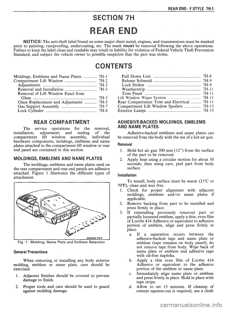
attached. Figure 1 illustrates the different types of
attachment.
Fig. 1 - Molding, Name Plate and Emblem Retention
General Precautions
When removing or installing any body exterior
molding, emblem or name plate, care should be
exercised.
1. Adjacent
finishes should be covered to prevent
damage to finish.
...................................... Pull Down Unit 7H-8
.......................................... Release Solenoid 7H-9
......... ..................................... Lock Striker ... 7H-9
................... ....................... Weatherstrip .. 7H- 1 1
.................................................. Trim Panel 7H- 1 1
..................... Lift Window Wiper System 7H- l l
......... Rear Compartment Trim and Electrical 7H- 1 1
............... Compartment Lift Window Spoilers 7H- 13
.......................................... Exterior Lamps 7H- 15
ADHESIVE-BACKED MOLDINGS, EMBLEMS
AND NAME PLATES
Adhesive-backed emblems and name plates can
be removed from the body with the use of a hot air gun.
Removal
1.
Hold hot air gun 300 mm (12") from the surface
of the part to be removed.
2. Apply heat using a circular motion for about 30
seconds; then using care, peel part from body
surface.
Installation
To install, body surface must be warm (21°C or
70"F), clean and wax free.
1. Check for proper alignment with adjacent
moldings, emblems and/or name plates if
applicable.
2. Remove backing from part to be installed and
press firmly in place.
3. If reinstalling previously removed part or
partially loosened emblem, apply a thin, even film
of Loctite 414 Adhesive or equivalent to adhesive
portion of emblem, align and press firmly in
place.
a. If a separation occurs between the
adhesive-backed tape and name plate or
emblem (tape remains on body panel), do
not remove tape from body. Wipe back of
name plate or emblem and adhesive tape
with oil-free naphtha.
b. Apply a thin even film of Loctite 414
Adhesive or equivalent to the adhesive
portion of the emblem or name plate.
c. Immediately align name plate or emblem
and press firmly in place. Hold in place with
tape strips.
2. Proper tools and care should be used to guard d. Allow to set 15 minutes. If cleanup of
against molding damage. cement squeeze-out is required, use a cloth
Page 1795 of 1825

91.1-1 2 SEATS - F STYLE
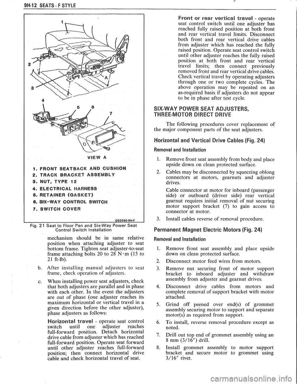
VIEW A
1. FRONT SEATBACK AND GUSHION
2. TRACK BRACKET AS8EMBLY
8. NUT, TYPE $2
4. ELECTRICAL HARNESS
5. RETAINER (GASKET)
8. SIX-WAY CONTROL SWITCH
7. SWITCH COVER
Fig. 2 1 Seat to Floor Pan and Six-Way Power Seat
Control Switch Installation
mechanism should be in same relative
position when attaching adjuster to seat
bottom frame. Tighten seat adjuster-to-seat
frame attaching bolts
20 to 28 N.m (15 to
21 ft-lb).
b. After installing manual adjusters to seat
frame, check operation of adjusters.
c. When installing power seat adjusters, check
that both adjusters are parallel and in phase
with each other. In the event the adjusters
are out of phase (one adjuster reaches its
maximum horizontal or vertical travel in a
given direction before the other adjuster),
phase adjusters as follows:
Horizonta! travel - operate seat control
switch until one adjuster reaches
full-forward position. Detach horizontal
drive cable from adjuster which has reached
full-forward position. Operate seat forward
until other adjuster reaches full-forward
position; then connect horizontal drive
cable and check horizontal travel of seat.
Front or rear vertical travel - operate
seat control switch until one adjuster has
reached fully raised position at both front
and rear vertical travel limits. Disconnect
both front and rear vertical drive cables
from adjuster which has reached the fully
raised position. Operate seat control switch
until other adjuster reaches the fully raised
position at both front and rear vertical
travel limits; then connect previously
removed front and rear vertical drive cables.
Check vertical travel by operating adjusters
through one or two complete cycles. The
above operation may be repeated on an
as-required basis if adjusters do not appear
to be in phase after test cycle.
SIX-WAY POWER SEAT ADJUSTERS,
THREE-MOTOR DIRECT DRIVE
The following procedures cover replacement of
the major component parts of the seat adjusters.
Horizontal and Vertical Drive Cables (Fig. 24)
Removal and Installation
1.
Remove front seat assembly from body and place
upside down on clean protected surface.
2. Cables may be disconnected by squeezing oblong
connectors at motors,
gearnuts and adjuster
drives.
Cable connector at motor for inboard (passenger
side) or outboard (driver side) rear vertical
gearnut requires initial removal of nut securing
motor support bracket (7) to gain access to
connector at motor.
3. Install cables reverse of removal procedure.
Permanent Magnet Electric Motors (Fig. 24)
Removal and Installation
1. Remove front seat assembly and place upside
down on clean protected surface.
2. Disconnect motor feed wires from motors.
3. Remove nut securing front of motor support
bracket to inboard adjuster and withdraw
assembly from adjuster and
gearnut drives.
4. Disconnect drive cables from motors and
complete removal of support bracket with motor
attached.
5. Grind off peened over
end(s) of grommet
assembly securing motor to support and separate
motor(s) as required from support.
6. To install, reverse removal procedure except as
noted.
7. Drill out top end of grommet assembly using an
8 mm
(3/16") drill.
8. Install grommet assembly to motor support
bracket and secure motor to grommet using
3/16" rivet.