1988 PONTIAC FIERO gas type
[x] Cancel search: gas typePage 472 of 1825
IGNITION SYSTEM 6B4-3
flash-over, which causes engine misfiring. Do not
mistake corona discharge for flash-over, or a shorted
insulator. Corona is a steady blue light appearing
around the insulator, just above the shell crimp. It is
the visible evidence of a high-tension field and has no
effect on ignition performance. Usually it can be
detected only in darkness. This discharge may repel
dust particles, leaving a clear ring on the insulator just
above the shell. This ring is sometimes mistakenly
regarded as evidence that combustion gases have blown
out between shell and insulator.
lgnition Switch
The mechanical switch is located in the steering
column on the right hand side just below the steering
wheel. The electrical switching portion of the assembly
is separate from the key and lock cylinder. However,
both are synchronized and work in conjunction with
each other through the action of the actuator rod
assembly.
For a complete explanation of the key and lock
cylinder, and the actuator rod assembly, see
STEERING, Section
38. See Section 8 for electrical
switching.
DIAGNOSIS
IGNITION SYSTEM
Spark Plugs
Worn or dirty plugs may give satisfactory
operation at idling speed, but at higher RPM they
frequently fail. Faulty plugs are indicated in a number
of ways: poor fuel economy, power loss, loss of speed,
hard starting and generally poor engine performance.
Spark plugs may also fail due to carbon fouling,
excessive gap, or a broken insulator. Fouled plugs may
be indicated by black carbon
deposits. The black deposits are usually the result of
slow-speed driving and short runs, where sufficient
engine operating temperature is seldom reached. Worn
pistons, rings, faulty ignition, over-rich carburetion
and spark plugs which are too cold will also result in
carbon deposits.
Excessive gap wear, on plugs of low mileage,
usually indicates the engine is operating at high speeds,
or loads that are consistently greater than normal, or
that a plug which is too hot is being used. Electrode
wear may also be the result of plug overheating,
causcd
by combustion gases leaking past the threads due to
insufficient torquing of the spark plug. Excessively lean
carburetion will also result in accelerated electrode
wear.
Broken insulators are usually the result of
improper installation, or carelessness when regapping
the plug. Broken upper insulators usually result from
a poor fitting wrench, or an outside blow. The cracked
insulator may not show up right away, but will as soon
as oil or moisture penetrates the crack. The crack is
usually just below the crimped part of shell and may
not be visible.
Broken lower insulators usually result from
carelessness when regapping and generally are visible.
This type of break may result from the plug operating
too "hot", which may happen in periods of high-speed
operation or under heavy loads. When regapping a
spark plug, always make the gap adjustment by
bending the ground (side) electrode. Spark plugs with
broken insulators should always be replaced.
HE1 Distributor
See Unit Repair for distributor disassembly, test
and reassembly of individual distributor components,
when the distributor is removed from the vehicle. See
On-Car Service for distributor removal and installation
and for component removal with distributor in car. See
Section 6E for
HE1 and EST diagnosis.
SERVICE PROCEDURES
IGNITION SYSTEM
Distributor Ignition
NOTICE: This procedure is generally true for
most carlines. Where procedure is different, or
where additional information is required, see
"ON-CAR SERVICE" for specific
carline.
HE1 DISTRIBUTOR
Service Precautions
1. When making compression checks, disconnect
the ignition switch feed wire at the distributor.
When disconnecting this connector,
do not use
a screwdriver or tool to release the locking tab, as
it may break.
2. No periodic lubrication is required. Engine oil
lubricates the lower bushing and an oil-filled
reservoir provides lubrication for the upper
bushing. 3.
The tachometer (TACH) terminal is next to the
ignition switch (BAT) connector on the
distributor cap.
NOTICE: The tachometer terminal must
NEVER be allowed to touch ground, as damage
to the module and/or ignition coil can result.
Some tachometers currently in use may NOT be
compatible with the High Energy Ignition System.
Consult the manufacturer of the tachometer if
questions arise.
4. Dwell adjustment is controlled by the module,
and cannot be adjusted.
5. The material used to construct the spark plug
cables is very soft. This cable will withstand more
heat and carry a higher voltage, but scuffing and
cutting become easier. The spark plug cables
must be routed correctly to prevent
chafing or
cutting. See Spark Plug Section. When removing
Page 558 of 1825
DRIVEABILPTY AND EMISSIONS 5.QL (VIN E) 6E2-C"1-3
MAT SENSOR (TYPICAL)
Figure C1-5 - MAT Sensor - Typical
When manifold pressure is high, vacuum is low. The
MAP
sensor is also used to measure barometric
pressure under certain conditions, which allows the
ECM to automatically adjust for different altitudes.
The ECM sends a 5-volt reference signal to the
MAP sensor. As the manifold pressure changes, the
electrical resistance of the sensor also changes. By
monitoring the sensor output voltage, the ECM knows
the manifold pressure. A higher pressure, low vacuum
(high voltage) requires more fuel, while a lower
pressure, higher vacuum (low voltage) requires less
fuel.
The
ECM uses the MAP sensor to control fuel delivery
and ignition timing.
A failure in the
MAP sensor circuit should set a
Code 33 or Code 34.
Manifold Air Temperature (MAT) Sensor
The manifold air temperature sensor (MAT) is a
thermistor, a resistor which changes value based on
the temperature of air entering the enigne. Low
temperature produces
a high resistance ( 100,000 ohms
at
- 40°C I- 40°F), while high temperature causes low
resistance (70 ohms at 130°C
I 226°F). The ECM
supplies a
5 volt signal to the sensor through a resistor
in the ECM and measures the voltage. The voltage
will be high when the intake air is cold and low when
the air is hot. By measuring the voltage, the ECM
knows the manifold air temperature.
The MAT sensor is also used to control spark
timing and to delay EGR when
intake air is cold.
A failure in the
MAT sensor circuit should set
either a Code 23 or Code 25.
Oxygen (02) Sensor
The exhaust oxygen sensor is mounted in the
exhaust system where it can monitor the
oxygen
content of the exhaust gas stream.
EXHAUST OXYGEN (02)
Figure C1-6 - Exhaust Oxygen (Oz) Sensor
The oxygen content in the exhaust reacts with the
oxygen sensor to produce a voltage output. This
voltage ranges from approximately
.1 volts (high 02 -
lean mixture) to .9 volts (low 02 - rich mixture).
By monitoring the voltage output of the O2 sensor,
the ECM will know what fuel mixture command to
give to the injector (lean mixture
- low voltage - rich
command, rich mixture
- high voltage - lean
command). This voltage can be measured with a
digital voltmeter having at least 10
Meg Ohms input
impedance. Use of standard shop type voltmeters will
result in very inaccurate readings.
'I'he 02 sensor, if open, should set a Code 13. A
shorted sensor circuit should set
a Code 44. A high
voltage in the circuit should set a Code 45. When any
of these codes are set, the car should run in the "Open
Loop" mode.
Throttle Position Sensor (TPS)
The throttle position sensor ('I'PS) is connected to
the throttle shaft on the
TBI unit (see Figure C1-7). It
is a potentiometer with one end connected to 5 volts
from the ECM and the other to ground. A third wire is
connected to the ECM to measure the voltage
from the
TPS. As the throttle valve angle is changed
(accelerator pedal moved), the output of the TPS also
changes. At a closed throttle position, the output of the
TPS is low (approximately
.5 volts). As the throttle
valve opens, the output increases so that, at wide-open
throttle, the output voltage should be approximately
5
volts.
By monitoring the output voltage from the TPS,
the
ECM can determine fuel delivery based on throttle
valve angle (driver
demand).If the sensor CKT is open,
the ECM will set a Trouble Code 22. If the circuit is
shorted, the ECM will think the vehicle is at WOT,
and a Trouble Code 21 will be set.
Page 583 of 1825
6E2-CZ-8 DRIVEABILITY AND EMISSIONS - 5.OL (VIN E)
a FUEL METER COVER A~ACHING SCREW ASSEMBLY - LONG
2 FUEL MmEW COVER AmAC#ING SCREW
ASSEMBLY - SHORT
1 FUEL MmEW COVER GASKET
FUEL METER BODY ASSEMBLY
a THROTTLE BODY /ASSEMBLY
FUEL MnER OUTL- GASKET
PRESSURE
REGUUTOR SUL
FUEL METER COVER ASSEMBLY
Figure C2-9 - Replacing Model 220 Fuel Meter Cover
FUEL INJECTOR ASSEMBLY
FUEL INJECTOR
lNLm FILTER
FUEL INJECTOR LOWER
"On RlNG
FUEL INJECTOR UPPER "On RlNG
FUEL INJEmR WASHER
NEL METER BODY ASSEMBLY
THROTTLE BODY ASSEMBLY
EP 0925 AS 11587
Figure C2-10 - Model TBI 220 Fuel Injector Parts
NOTSCE: DO NOT immerse the fuel meter
cover (with pressure regulator) in
cleaner, as damage to the regulator
diaphragm and gasket could occur.
4. Fuel meter outlet gasket, cover gasket and
pressure regulator seal. Discard gaskets and seal.
inspect
@ For dirt, foreign material and casting warpage.
Install or Connect
I. New pressure regulator seal, fuel meter outlet
passage gasket, and cover gasket.
'2. Fuel meter cover assembly.
3. Attaching screw assetnblies, coated with
appropriate locking compound to threads. (Short
screws are next to injectors.)
Tighten
e Screw assemblies to 3.0 N.m (28.0 Ib. in.).
4. Electrical connectors to fuel injectors.
5. With engine "OFF", and ignition "ON", check for
leaks around gasket and fuel line couplings.
FUEL INJECTOR ASSEMBLIES
Replacement (Figure CZ-10 to CZ-13)
Each fuel injector is serviced as a complete
assembly only.
FUEL METER COVER GASKET
I Figure C2 - 11 - Removing Ti31 220 Fuel Injector
NOTICE: Use care in removing the Cuel injectors to
prevent
clamage to the electrical connector
terminals, the
in,jector filter, and the fuel
nozzle. Also, since the injectors are
electrical components, they should not be
immersecl in any type of lirluid solvent or
cleaner
as clatnuge may occur.
Page 586 of 1825
DRIVEABILITY AND EMISSIONS - 5.0L (VIN E) 6EZ-CZ-11
IDLE AIR CONTROL (IAC) VALVE
IAC VALVE GASKET
THROTTLE BODY ASSEMBLY
Figure C2-16 - Thread-Type IAC Valve
Install or Connect
1. TPS on throttle body assembly, while lining up
TPS lever with TPS drive lever on throttle body.
2. Two
TPS attaching screw assemblies.
Tighten
@ Screw assemblies to 2.0 N-m (18.0 in.lbs.).
3. Electrical connector.
4. Check for TPS output as follows: - Use an ALDL scanner to read TPS output
voltage.
- With ignition "ON" and engine stopped, TPS
voltage should be less than 1.25 volts. If more
than 1.25 volts, replace TPS.
IDLE AIR CONTROL (IAC) VALVE
Replacement (Figure CZ-16)
NOTICE:
The IAC valve is an electrical
component
and must not be soaked in any liquid
cleaner or solvent. Otherwise
damage
could result.
Important
All thread-mounted IAC valves on Model 220 TBI
units have a dual taper, 10 mm diameter, pintle.
Any replacement of an IAC valve must have the
correct part number with the appropriate pintle
taper and diameter for proper seating of the valve
in the throttle body.
Remove or Disconnect
1. Electrical connector.
2. IAC valve, using 32 mm (1-114") wrench.
3. IAC
valve gasket and discard.
Clean
@ Old gasket material from surface of throttle body
assembly to insure proper seal of new gasket.
NOTICE: If the IAC valve has been removed during
service, its operation may be tested
electrically with the
IACIISC Motor Tester
(Available Tool
# 5-37027, or BT-8256K).
However, if the valve pintle is extended
electrically, it must also be retracted
electrically. Under no circumstances
should the valve pintle be tampered with
by hand, screwed, or pushed in, or pulled
out, as damage could occur.
Important
No physical adjustment of the IAC valve assembly
is required after installation. The IAC valve is
reset by the ECM. When the vehicle is operated at
normal engine temperature at approximately 40
mph (64
kmlhr.), the ECM causes the valve pintle
to seat in the throttle body. The ECM then resets
the pintle to the correct position. Proper idle
regulation should result.
Install or Connect
1. IAC valve with new gasket into throttle body
NOTICE: New IAC valves that have been preset
at the factory should be installed in
the throttle
body in an "as is"
condition, without any adjustment.
Tighten
@ IAC valve assembly to 18.0 N.m (13.0 lb. ft.)
with 32 mm
(1-114") wrench.
2. Electrical connector to IAC valve.
3. Start engine and allow engine to reach operating
temperature.
Important
When the engine is turned "OFF," the IAC valve
will be reset by the ECM.
THROTTLE BODY ASSEMBLY
Replacement (Figure CZ-8)
NOTICE:
Procedures related to replacement of the
individual components below have been
described previously and should be
followed, or damage could occur.
Remove or Disconnect
1. Throttle body injection unit, described below
2. Fuel
meter body-to-throttle hodv attaching ~CI'PW
.i~~rmhlie
Page 588 of 1825
DRIVEABILITY AND EMISSIONS - S.0L (VIN E) 6EZ-C2-13
"THROTTLE BODY INJECTION (TBI) UNIT
Replacement (Figure C2-18)
a Remove or Disconnect
1. THERMAC hose from engine fitting.
2. Electrical connectors to IAC valve, TPS and fuel
injectors.
3. Grommet with wires from throttle body.
4. Throttle linkage, return
spring(s) transmission
control cable and cruise control (wherever
applicable).
5. Vacuum hoses (noting position of hoses) and
bracket.
6. Fuel inlet and return lines (use back-up wrench
J-29698-A or BT-8251-A). Discard o-
rings from
nuts.
7. TBI mounting hardware.
8. TBI flange (manifold mounting) gasket and
discard.
NOTICE: Stuff manifold opening with a rag to
prevent material from entering
engine, and remove old gasket
material from surface of intake
manifold.
Inspect
@ Intake manifold bore for loose parts and foreign
material, etc.
@ Intake manifold sealing surface for cleanliness.
Install or Connect
1. New TBI flange (manifold mounting) gasket.
2.
TI31 with mounting hardware.
Tighten
@ Hardwareto, 16.5N-m( 12Ib. ft.).
3. New o-rings on fuel line nuts
4. Fuel inlet and outlet lines.
Tighten - @ To 23 N.m (17 lb. ft.). (Use back-up wrench
J-29698-A or BT-8251-A to keep TBI nuts
from turning.)
5. Vacuum hoses and bracket.
6. Throttle linkage, return
spring(s) transmission
control cable and cruise control (wherever
applicable).
7. Grommet with wire harness to throttle body.
8. Electrical connectors, making sure connectors are
fully seated and latched.
9. Check to see if accelerator pedal is free by
depressing pedal to the floor
and releasing while
engine is "OFF".
10. With engine "OFF," and ignition "ON," check for
leaks around fuel line nuts.
11. Start engine and check for fuel leaks.
FUEL HOSEIPIPE ASSEMBLIES
Materials
Fuel Lines. These are welded steel tubes, meeting GM
Specification 124-M, or its equivalent. The fuel feed
line is
318" diameter, and the fuel return line is 5/16"
diameter. Do not use copper or aluminum tubing to
replace steel tubing. Those materials do not have
satisfactory durability to withstand normal vehicle
vibr, ii t' lon.
Clamps. These are stainless steel, screw band type
clamps,
#249472, or equivalent.
Coupled Hose. These are not to be repaired and are
replaced
&as an assembly.
Uncoupled Hose. Use only reinforced fuel resistant
hose, made of "fluroelastomer" material.
[lo not use w
hose within 4 inches (100 mm) of any part of the
exhaust system, or within 10 inches
(254 mm) of the
catalytic converter. The hose's inside diameter nus st
match the outside diameter of the steel tubing.
Fuel Line Repair
1. Cut
a piece of fuel hose 4 inches (100 mm) longer
than the section of line to be removed. If
more
than 6 inches (152 tnm) is to be removed, use a .
combination of steel pipe and hose. The
hose
length should not be more than 10 inches total.
2. Cut a section of pipe to be replacccl, with a tube
cutter. C'se the first step of a double flaring tool to
form a bead on the ends
of the pipe and also, on the
new section of pipe, if used.
3. Slide
the hose
clanlps onto the pip2 and push the
hose
2 inches (51 mm) onto each portion of the fuel
pipe. Tighten a
clamp on each side of the repair.
4. Secure
fuel line to the frame.
FUEL PUMP RELAY
(Figure
CZ-19)
The fuel pump relay is mounted in the engine
compartment. Other than checking for loose
connectors, the only service possible is replacement.
OIL PRESSURE SWITCH
(Figure C2-20)
The oil pressure switch is li~ounted on the engine.
This switch is a parallel power supply, with the fuel
pump relay, and will provide battery voltage to the
fuel
pump, after approximately 28 kPa (4 psi) oil
pressure is reached.
Page 647 of 1825
FUNCTIONAL CHECKS/
DIAGNOSTIC CHARTS
2.8L (VIN S)
ECM QDR Check
......................... Chart C-1 C1-10
ParkINeutral Switch
......................... Chart C-1A C1-12
Power Steering Pressure Switch Check
........................ ChartC-1E C1-14
Injector Balance Test
........................ Chart C-2A C2-18
Idle Air Control
........................ Chart C-2C C2-20
Canister Purge Valve Check
......................... Chart C-3 C3-4
Ignition System Check
........................ Chart C-4A C4-4
Electr~c Control (Divert) -(Manual Transmission)
......................... Chart C-6 C6-6
Exhaust Gas Recirculation Check
........................ Chart C-7 C7-6
Automatic Transmission
Converter Clutch (TCC)
. (I of 2)
........................ Chart C-8 C8-2
Transmiss~on Converter Clutch
(TCC) Electrical Diagnosis
. (2 of 2)
........................ Chart C-8 C8-4
A/C Clutch Control
........................ Chart C-10 C10-2
Cooling Fan Control Circuit (I of 2)
........................ Chart C-12 C12-2
Cooling Fan Control Circuit (2 of 2)
........................ Chart C-12 C12-4
ParklNeutral Switch (Auto Only) ...... C1-4
AIC "ON" Signal .................. C1-4
Distributor Reference Signal ......... C1-4
......................... DIAGNOSIS C1-4
............................. ECM C1-4
........................... PROM C1-4
...................... ECM Inputs C1-5
Coolant Temp . Sensor ............. C1-5
..................... MAFSensor C1-5
..................... MAT Sensor C1-5
....................... 02Sensor C1-5
TPS ............................ C1-5
........................... VSS C1-5
...................... PIN Switch C1-5
................ A/C Request Signal C1-5
Power Steering Pressure Switch ...... C1-5
................. Reference Signal C1-5
ON-CAR SERVICE ..................... C1-5
ELECTRONIC CONTROL MODULE (ECM) . . C1-5
ECM & COMPONENTS REPLACEMENT
..................... PROM OR ECM C1-6
................. Functional Check C1-7
CALPAK .......................... C1-7
COOLANT SENSOR .................. C1-7
MAFSENSOR ...................... C1-7
MAF SENSOR POWER & BURN-OFF RELAY . C1-7
................... OXYGEN SENSOR C1-8
Throttle Position Sensor ............ C1-8
PARKINEUTRALSWITCH .............. C1-9
................. PARTS INFORMATION C1-9
ECM QDR Check
................... ... Chart C-1 ... C1-10
ParktNeutral Switch
........................ ChartC-1A C1-12
Power Steering Pressure Switch Check
........................ SECTION C . COMPONENT SYSTEMS ChartC-lE C1-14
2.8L (VIN S) SECTION C2 . 2.8L (WIN S)
FUEL CONTROL SYSTEM
................ 'Table of Contents .................... C-1 GENERAL DESCRIPTION C2-1
SECTION
C1 . 2.8L (VIN S)
ELECTRONIC CONTROL MODULE (ECM)
& SENSORS
ELECTRONIC CONTROL MODULE (ECM) ... C1-1
........................ ECM TYPES C1-1
........................... PROM C1-1
CALPAK .......................... C1-2
.................... ECM Function C1-2
............. INFORMATION SENSORS C1-2
Engine Coolant Temp . Sensor ........ C1-2
Mass Air Flow (MAF) Sensor ......... C1-2
.................. A/C MAF Sensor Cl-2
Manifold Air Temp . (MAT) Sensor ..... C1-2
Oxygen (Oz)Sensor ............... C1-3
Throttle Position Sensor (TPS) ........ C1-3
Vehicle Speed Sensor .............. C1-3
ParkINeutral Switch (Auto Only) ...... C1-4
......................... PURPOSE C2-1
.............. MODES OF OPERATION C2-1
................... Starting Mode C2-2
................. Clear Flood Mode C2-2
...................... Run Mode C2-2
................ Acceleration Mode C2-2
............... Deceleration Mode C2-2
Battery Voltage Correction Mode ..... C2-2
................. Fuel Cutoff Mode C2-3
Fuel Control System Components ..... C2-3
Basic System Operat~on ............. C2-3
THROTTLEBODY UNIT ............... C2-3
......................... FUELRAIL C2-3
..................... FUEL INJECTOR C2-3
............... PRESSURE REGULATOR C2-3
IDLE AIR CONTROL (IAC) VALVE ........ C2-4
Page 722 of 1825
The ECM supplies a 5-volt signal to the sensor
thru
a resistor in the ECM and measures the voltage.
The voltage will be high when the manifold air is cold,
and low when the air is hot. By measuring the
voltage, the ECM knows the manifold air
temperature.
The
2.8L uses the signal to slightly retard the
timing during high ambient air temperatures and to
help compensate the MAF sensor based on air
temperature.
A failure in the MAT sensor circuit should set
either a Code
23 or Code 25.
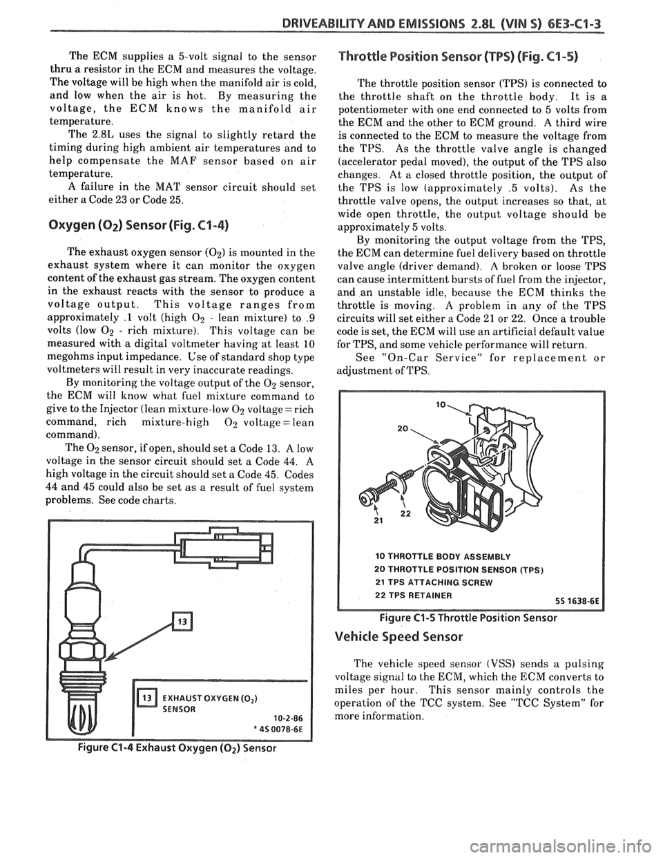
Oxygen (02) Sensor (Fig. C1-4)
The exhaust oxygen sensor (02) is mounted in the
exhaust system where it can monitor the oxygen
content of the exhaust gas stream. The oxygen content
in the exhaust reacts with the sensor to produce a
voltage output. This voltage ranges from
approximately
.1 volt (high 02 - lean mixture) to .9
volts (low 02 - rich mixture). This voltage can be
measured with a digital voltmeter having at least
10
megohms input impedance. Use of standard shop type
voltmeters will result in very inaccurate readings.
By monitoring the voltage output of the
02 sensor,
the ECM will know what fuel mixture command to
give to the Injector (lean mixture-low
02 voltage = rich
command, rich mixture-high
02 voltage = lean
command). The
02 sensor, if open, should set a Code 13. A low
voltage in the sensor circuit should set a Code 44. A
high voltage in the circuit should set a Code 45. Codes
44 and 45 could also be set
as a result of fuel system
problems. See code charts.
Throttle Position Sensor (PPS) (Fig. C4-5)
The throttle position sensor (TPS) is connected to
the throttle shaft on the throttle body. It is
a
potentiometer with one end connected to 5 volts from
the ECM and the other to ECM ground.
A third wire
is connected to the ECM to measure the voltage from
the TPS. As the throttle valve angle is changed
(accelerator pedal moved), the output of the TPS also
changes. At a closed throttle position, the output of
the TPS is low (approximately
.5 volts). As the
throttle valve opens, the output increases so that, at
wide open throttle, the output voltage should be
approximately 5 volts.
By monitoring the output voltage from the TPS,
the ECM can determine fuel delivery based on throttle
valve angle (driver demand). A
broken or loose TPS
can cause intermittent bursts of fuel from the injector,
and an unstable idle, because the ECM thinks the
throttle is moving.
A problem in any of the TPS
circuits will set either
a Code 21 or 22. Once a trouble
code is set, the ECM will use an artificial default value
for TPS, and some vehicle performance will return.
See "On-Car Service" for replacement or
adjustment of TPS.
10 THROTTLE BODY ASSEMBLY
20 THROTTLE POSITION SENSOR (TPS)
21 TPS ATTACHING SCREW
22 TPS RETAINER 55 1638-6E
Figure C1-5 Throttle Position Sensor
Vehicle Speed Sensor
The vehicle speed sensor (VSS) sends a pulsing
voltage signal to the ECM, which the ECM converts to
miles per hour. This sensor mainly controls the
operation of the TCC system. See "TCC System" for
more information.
Page 749 of 1825
6E3-CZ-14 2.8L (VIN S) DRlVEABlLlTV AND EMISSIONS
MINIMUM IDLE SPEED ADJUSTMENT
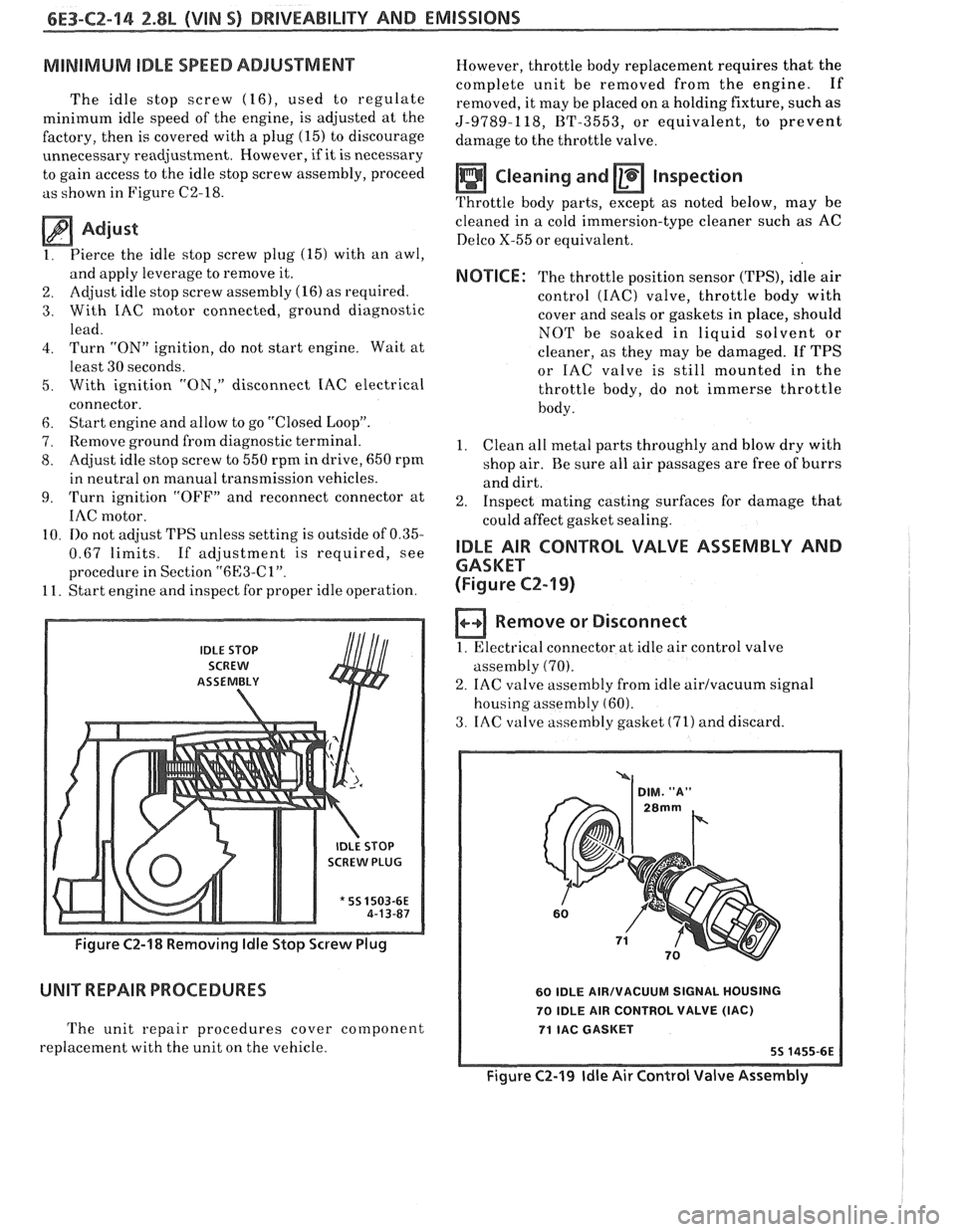
The idle stop screw (16), used to regulate
minimum idle speed of the engine, is adjusted at the
factory, then is covered with a plug
(15) to discourage
unnecessary readjustment. However,
if it is necessary
to gain access to the idle stop screw assembly, proceed
as shown in Figure C2-18.
Adjust
1. Pierce
the idle stop screw plug (15) with an awl,
and apply leverage to remove it.
2. Adjust idle
stop screw assembly (16) as required.
3. With IAC motor connected, ground diagnostic
lead.
4. Turn "ON" ignition, do not start engine. Wait at
least 30 seconds.
5. With ignition "ON," disconnect IAC electrical
connector.
6. Start engine and allow to go "Closed Loop".
7. Remove ground from diagnostic terminal.
8. Adjust idle stop screw to 550 rpm in drive, 650 rpm
in neutral on manual transmission vehicles.
9. Turn ignition "OFF7' and reconnect connector at
IAC motor.
10.
110 not adjust TPS unless setting is outside of 0.35-
0.67 limits. If adjustment is required, see
procedure in Section
"6l33-Cl".
11. Start engine and inspect for proper idle operation.
IDLE STOP
SCREW
ASSEtVIBLY
SCREW PLUG
* 55 1503-6E
Figure C2-18 Removing ldle Stop Screw Plug
UNIT REPAIR PROCEDURES
The unit repair procedures cover component
replacement with the unit on the vehicle. However,
throttle body replacement requires that the
complete unit be removed from the engine. If
removed, it may be placed on a holding fixture, such as
5-9789-118, BT-3553, or equivalent, to prevent
damage to the throttle valve.
Cleaning and Inspection
Throttle body parts, except as noted below, may be
cleaned in
a cold immersion-type cleaner such as AC
Delco X-55 or equivalent.
NOTICE: The throttle position sensor (TPS), idle air
control
(IAC) valve, throttle body with
cover and seals or gaskets in place, should
NOT be soaked in liquid solvent or
cleaner, as they may be damaged. If TPS
or IAC valve is still mounted in the
throttle body, do not immerse throttle
body.
1. Clean
all metal parts throughly and blow dry with
shop air. Be sure all air passages are free of burrs
and dirt.
2. Inspect mating casting surfaces for damage that
could affect gasket sealing.
IDLE AIR CONTROL VALVE ASSEMBLY AND
GASKET
(Figure
CZ-19)
Remove or Disconnect
1. Electrical connector at idle air control valve
assembly
(70).
2. IAC valve assembly from idle airlvacuum signal
housing assembly
(60).
3. IAC valve assembly gasket (71) and discard.
60 IDLE AIRIVACUUM SIGNAL HOUSING
70 IDLE AIR CONTROL VALVE
(IAC)
71 IAC GASKET
Figure C2-19 ldle Air Control Valve Assembly