1988 PONTIAC FIERO gas type
[x] Cancel search: gas typePage 878 of 1825
DRIVEABILITY AND EMISSIONS 5.OL (VIN F) & 5.7L (VIN 8) 6E3-C1-3
The MAT sensor signal is used by the ECM to
delay
EGR until the manifold air temperature reaches
about 5°C
(40°F).
A failure in the MAT sensor circuit should set
either a Code
23 or Code 25.
Oxygen (02) Sensor
(Figure
€3-4)
The exhaust oxygen sensor (02) is mounted in the
exhaust system, where it can monitor the oxygen
content of the exhaust gas stream. The oxygen content
in the exhaust reacts with the sensor to produce a
voltage output. This voltage ranges from
approximately
.l volt (high 02 - lean mixture) to .9
volts (low 02 - rich mixture). This voltage can be
measured with a digital voltmeter having at least 10
meg ohms input impedance. Use of standard shop
type voltmeters will result in very inaccurate
readings.
By monitoring the voltage output of the 02 sensor,
the ECM will know what fuel mixture command to
give to the Injector (lean mixture-low
02 voltage= rich
command, rich mixture-high
O2 voltage = lean
command). The
02 sensor, if open, should set a Code 13. A low
voltage in the sensor circuit should set a Code
44. A
high voltage in the circuit should set a Code 45. Codes
44 and 45 could also be set as a result of fuel system
problems. See Code Charts.
EXHAUST OXYGEN (02)
10-2-86
* 45 0078-6E
Figure C1-4 E- xhaust Oxygen (Oz) Sensor
Throttle Position Sensor (TPS)
(Figure C1-5)
The throttle position sensor (TPS) is connected to
the throttle shaft on the throttle body. It is a
potentiometer with one end connected to
5 volts from
the ECM and the other to ECM ground.
A third wire
is connected to the ECM to measure the voltage from
the TPS. As the throttle valve angle is changed
(accelerator pedal moved), the output of the TPS also
changes. At a closed throttle position, the output of the TPS
is low (approximately
.5 volts). As the throttle
valve opens, the output increases so that, at wide-open
throttle, the output voltage should be approximately
5
volts.
By monitoring the output voltage from the
TPS,
the ECM can determine fuel delivery based on throttle
valve angle (driver demand).
A broken or loose 'I'PS
can cause intermittent bursts of fuel from the injector
and an unstable idle, because the ECM thinks the
throttle is moving.
A problem in any of the TPS
circuits will set either a Code
21 or 22. Once a trouble
code is set, the ECM will use an artificial default value
for TPS, and some vehicle perfhrmance will return.
See "On-Car Service" for replacement or
adjustment of
TPS.
10 THROTTLE BODY ASSEMBLY
20 THROTTLE POSITION SENSOR (TPS)
Figure
C1-5 - Throttle Position Sensor
Knock Sensor
This sensor is used to control engine detonation
Refer to Section
"C5", for description.
Vehicle Speed Sensor
The vehicle speed sensor (VSS), part of the digital
cluster, sends a pulsing voltage signal to the ECM,
which the ECM converts to miles per hour.
This
sensor mainly controls the operation of the 'I'CC
system. See Code 24 or Section "C8" for more
information.
ParklNeutral Switch (Auto Only)
The parWneutra1 (PIN) switch indicates to the
ECM when the transmission is in park or neutral.
This information is used for the TCC and the
IAC
valve operation.
Important
Vehicle should not be driven with parklneutral
switch disconnected, as idle quality will be aft'ected
,ind a poss~hle false Code 24 (VSS).
Page 899 of 1825
6E3-C2-12 5.OL (VIN F) & 5.7L (VIN 8) DRIVEABILITY AND EMISSIONS
UNIT REPAIR PROCEDURES
Figure C2-14 Throttle Body Removal
THROTTLE BODY SERVICE
IDENTIFICATION
An eight digit identification number is stamped
on the throttle body casting, next to the coolant cover,
as shown in Figure C2-15. Refer to this model
identification number if servicing or part replacement
is required.
Names of component parts will be found on the
numbered list that accompanies the exploded view
(Figure
C2-18). Numbers used to identify parts in the
exploded views also are used to identify the same parts
in other illustrations of this manual.
IDENTIFICATION NUMBER
Figure C2-15 Throttle Body Identification
TPS Adjustment
Refer to Section "C-1" for TPS replacement or
adjustment. The unit repair procedures cover component
replacement with the unit on the vehicle. However,
throttle body replacement requires that the complete
unit be removed from the engine. If removed, it may
be placed on a holding fixture, such as
5-9789-118, BT-
3553, or equivalent, to prevent damage to the throttle
valve.
Cleaning and a Inspection
Throttle body parts, except as noted below, may be
cleaned in a cold-immersion-type cleaner such
a; AC
Delco X-55 or equivalent.
NOTICE: The throttle position sensor (TPS), idle air
control
(IAC) valve, throttle body with
cover and seals or gaskets in place, should
NOT be soaked in liquid solvent or
cleaner, as they may be damaged. If TPS
or IAC valve is still mounted in the
throttle body, do not immerse throttle
body.
I. Clean all metal parts throughly and blow dry with
shop air. Be sure all air passages are free of burrs
and dirt.
2. Inspect mating casting surfaces for damage that
could affect gasket sealing.
MINIMUM IDLE SPEED CHECK
The idle stop screw (161, used to regulate
minimum idle speed of the engine, is adjusted at the.
factory, then is covered with a plug (15) to discourage
unnecessary readjustment. However, if it is necessary
to gain access to the idle stop screw assembly, proceed
as shown in Figure C2-16.
Before checking minimum idle speed, be sure
ignition timing is correct and, before making any idle
speed adjustments, be sure throttle body is clean
around the throttle plates.
Adjust
1. Pierce
the idle stop screw plug (15) with an awl,
and apply leverage to remove it.
2. Adjust idle stop screw assembly
(16) as required.
Page 970 of 1825
DRIVEABILITY AND EMISSIONS - FUEL INJECTION 6E-9
ParWNelatral Switch IAC (Idle Air Control)
The indication in this mode may vary with This system is used to control engine idle speed to
manufacturer so the type of reading for a particular the desired rpm, for different operating conditions. In
tool should be checked in the operator's manual. The this mode, the numbers will indicate the position to
important thing is that the the reading changes state which
the ECM has moved the valve pintle. The ECM
(switches) when the gear selector is moved from moves
the IAC in counts, or steps, and the number of
paridneutral to drive or reverse. these counts are displayed on a "Scan" tool.
"Trque Convertor Clutch (TCC)
In this position, the tool will indicate when the
TCC has been commanded by the ECM to turn "ONJ'.
This does not necessarily mean that the clutch was
engaged but only that the
ECM grounded the circuit
internally. The best way to determine if the clutch has
engaged is to monitor engine rpm when the TCC
comes "ON".
EGR (Duty Cycle)
The EGR system uses a valve to feed a small
amount of exhaust gas back into the intake manifold
to control formation of NO,. Like all ECM outputs, the
"Scan" tool only indicates that the ECM has
commanded the function, and does not indicate that
the function has really happened.
EGR Position
This indicates the position of the EGR pintle.
Integrator and Block Learn
Normal readings for these positions are around
128. If higher, it indicates that the ECM is adding fuel
to the base fuel calculation because the system is lean,
and if the numbers are below 128, the ECM is taking
out fuel from the base calculation because the system
is rich. The integrator gives short term corrective
action, while the block learn portion (which is a long
term correction) will only change if the integrator has
seen a condition which lasts for a calibrated period of
time.
Block Learn Multiplier (BLM) Cell - or -
Block Learn Memory (BLM)
There are up to sixteen different cells,
corresponding to ranges of rpm and engine load
(indicated by MAF or MAP signals), and other
conditions, such as
A/C or P/N switch "ON" or "OFF",
etc. The ECM learns how much adjustment is needed
in each cell, and retains it in memory, so that the
adjustment will immediately be made when the
engine operates in that cell (or
rpmlload range). This
parameter will display what cell the ECM is currently
using for the fuel calculation.
Desired RPM
This indicates the rpm to which the ECM is trying
to control the idle.
Shift Light
This displays "yes" when the ECM is commanding
the shift light to turn "ON".
PPSW (Pump Prime Switch)
This is the voltage on the fuel pump feed circuit.
The ECM will adjust fuel injector base pulse width
from this voltage value rather than from battery
voltage.
NC Request
The state of the A/C signal line to the ECM is
shown. It should read "yes" whenever the
IVC is
requested.
NC Clutch
"ON" is displayed when the ECM has commanded
the
A/C clutch "ON".
Knock Retard
This indicates the number of degrees the ECM is
retarding the electronic spark timing (EST).
Knock Signal
This displays a "yes" when knock is detected by
the ECM, and a "no" when knock is not detected.
Battery Voltage
This displays the battery voltage detected at the
ECM ignition input.
Fan
"ON" is displayed when the cooling fan has been
commanded "ON".
Page 971 of 1825
6E-18 DRIVEABILITY AND EMISSIONS - FUEL INJECRON
CCP (Carbon Canister Purge)
This displays "ON" when the canister purge
solenoid is commanding purge. Some display duty
cycle from
0-1008.
2nd Gear
This displays the state of the 2nd gear switch.
Yes=2nd gear applied. It remains applied in 3rd and
4th gears.
3rd Gear
This displays the state of the 3rd gear switch.
Yes= 3rd gear applied. It remains applied in 4th gear.
4th Gear
This displays the state of the 4th gear switch.
Yes
= 4th gear applied.
Fan Request
State of the AJC fan control switch is displayed. It
should read "yes" when fan is requested. Some
engines may display the state of the 2nd fan, if used.
Power Steering Pressure Switch
This reading displays the state of switch, and may
vary with the tool used, and the type of switch
installed on the vehicle. The important thing is that
the reading changes state (switches) when the
steering is moved against the stops.
Electronic Control Module (ECM)
This section describes the ECM and the
information sensors in the system. Figure
4 shows
the operating conditions which the ECM may sense
and the systems that the ECM may control. (See
specific engines to determine which are applicable
to
that engine.)
Fuel Control System
The ECM controls the aidfuel delivery to the
combustion chamber by controlling the fuel flow
through the
injector(s).
Electric Fuel Pump (In-tank)
The in-tank fuel pump is controlled by the ECM.
When ignition is turned "ON", the pump will run for 2
seconds, then stop unless the ECM is receiving
ignition pulses, as when cranking or running.
Evaporative Emission ControI
This system has a canister which stores fuel vapor
from the fuel tank. The fuel vapor is removed from the
canister and consumed in the normal combustion
process when the engine is running. This system is
used on all engines and may or may not be controlled
by the ECM.
ilectronic Spark Timing (EST)
This system is controlled by the ECM, which
controls spark advance (timing), and is used on all
engines.
SECTION B - DRIVEABILIW SYMPTOMS Electronic Spark
Control (ESC)
Always start with Section "A" "Diagnostic Circuit
Check" before proceeding to the driveability
symptoms or an emissions test failure. Section "A"
checks the ECM, which may cause the driveability
problem. A definition of each symptom is included.
This will then lead to the most probable causes of the
driveability problem.
SECTION C - COMPONENT SYSTEMS
There are many component systems that are used
to control fuel and emissions. Section
"C" introduces
each component system or control with a general
description, diagnosis, and on-vehicle service.
Each of the Section "C" diagnosis sections contain
information on how the "ScanJ' tool can be used for
diagnosing a particular component when a trouble
code has not been set. (example: Section
"Cl" under
diagnosis will explain how the "Scan" tool can be used
for diagnosis as well as what the normal readings
would be for the
ECM sensors.) This
system uses a knock sensor in connection
with the ECM to control spark timing, to allow the
engine to have maximum spark advance without
spark knock. This improves driveability and fuel
economy, but will retard spark
if detonation (spark
knock) is detected.
Air Injection Reaction (A.I.R.)
The system provides additional oxygen to the
exhaust gases to continue the combustion process.
The system also supplies additional air to the catalytic
converter under certain conditions. The A.I.R. system
is not on all engines.
Early Fuel Evaporation (EFE)
The EFE system heats the engine induction
system electrically or with exhaust gas during cold
Page 973 of 1825
6E-12 DRIVEABILITY AND EMISSIONS - FUEL INJECUION
and MPH) for abbreviations used in this Section, but
all types are acceptable.
NA/F - AI WFUEL (NF RATIO)
A.I.R.
- AIR INJECTOR REACTION SYSTEM - Air
flow from pump is directed into engine exhaust
manifold
and/or converter to reduce exhaust
emissions.
ALDL - ASSEMBLY LINE DIAGNOSTIC LINK - Used
at assembly to evaluate Computer Command Control,
and for service to flash the "Service Engine Soon"
light
if there are trouble codes. It also is used by
"Scan" tools to obtain ECM serial data.
BARO - BAROMETRIC ABSOLUTE PRESSURE
SENSOR
- Reads atmospheric pressure.
B + - Battery Positive Terminal (12 Volts) or
system voltage with the engine running
(approximately 13.8
v.)
CALPAK - A device used with fuel injection to
allow fuel delivery in the event of a PROM or ECM
malfunction.
CALIBRATOR - (PROM) - An electronic component
that can be
specifically programmed to meet engine
operating requirements for a
specific vehicle model.
It plugs into the Engine Control Module
(ECM).
CCC - COMPUTER COMMAND CONTROL - has an
electronic control module to control airlfuel and
emission systems.
CLCC - CLOSED LOOP CARBURETOR CONTROL -
Used to describe oxygen sensor to ECM to MIC
solenoid circuit operation.
C3I - Computer Controlled Coil Ignition. Produces
the ignition spark without the aid of an ignition
distributor.
CCP - CONTROLLED CANISTER PURGE - ECM
controlled solenoid valve that permits manifold
vacuum to purge the evaporative emissions from the
charcoal canister.
CID - CUBIC INCH DISPLACEMENT - Used to
describe engine size.
UL OR ULOOP - "CLOSED LOOP" - Describes ECM
fuel control when using oxygen sensor information.
COOLANT TEMPERATURE SENSOR - Device that
senses the engine coolant temperature, and passes
that information to the engine control module.
CONV. - CATALYTIC CONVERTER, THREE-WAY -
EXHAUST CONVERTER. Containing platinum and
palladium to speed up conversion of
HC and CO, and
rhodium to accelerate conversion of NO,.
CO - CARBON MONOXIDE - One of the pollutants
found in engine exhaust.
6V - CRANKCASE VENTlhaflON - Prevents fumes
in crankcase from passing into the atmosphere, by
drawing them into the intake manifold and burning
them in the the combustion process.
DIAGNOSTIC CODE - Pair of numbers obtained
from flashing "Service Engine Soon" light or
displaying on a "Scan" tool. This code can be used to
determine the system malfunction.
DIAGNOSTIC TERM. - Lead of ALDL Connector
which is grounded to get a Trouble Code.
It is
grounded with the engine running to enter the "Field
Service Mode".
DIS - Direct Ignition System. Produces the
ignition spark without the aid of an ignition
distributor.
DVM (10 Meg.) - Digital Voltmeter with 10 Million
ohms resistance
- used for measurement in electronic
systems.
DWELL - The amount of time (recorded on a dwell
meter in degrees of crankshaft rotation) that current
passes through a closed switch; for example, ignition
contact points or internal switch in an electronic
control module.
EAC - ELECTRIC AIR CONTROL - Used on A.I.R.
system to direct air flow to air switching valve or to
atmosphere.
EAS - ELECTRIC AIR SWITCHING - used to direct air
flow to catalytic converter or exhaust ports of the
engine.
ECM - ENGINE CONTROL MODULE (ELECTRONIC) -
A metal case (located in passenger compartment)
containing electronic circuitry which electrically
controls and monitors airlfuel and emission systems
on computer command control, and turns
"ON" the
"Service Engine Soon" light when a malfunction
occurs in the system.
EFI - ELECTRONIC FUEL INJECTION - Computer
Command Control using throttle body fuel injection.
EGR - EXHAUST GAP REClRCUbATlON - Method of
reducing NO, emission levels by causing exhaust gas
to be added to airlfuel mixture in combustion
chamber, thus cooling combustion.
EECS - EVAPORATIVE EMISSIONS CONTROL
SYSTEM
- Used to prevent gasoline vapors in the fuel
tank from entering the atmosphere.
EFE - EARLY FUEL EVAPORATION - Method of
warming the intake manifold during cold engine
operation. Provides efficient airlfuel mixing.
ENERGIZEIDE-ENERGIZE - When current is passed
through a coil (energized) such as the canister purge
solenoid, the plunger is pulled into the solenoid.
Page 986 of 1825
EXHAUST SYSTEM 6F-1
SEC"B0N 6F
EXHAUST SYSTEM
CAUTION: Exhaust system components should avoid overheating and possible damage to the
have enough clearance from the underbody to passenger compartment carpets.
................................. General Description 6F- 1 Hanger ............................................................ 6F- I
..................... ....................... Exhaust Pipe .. 6F- I Clamp ............................................................ 6F- I
Muffler .......................................................... 6F- 1 Catalytic Converter ......................................... 6F- 1
.......................... Resonator ........................... .. 6F- 1
GENERAL DESGRIP"F0N
When inspecting or replacing exhaust system
components, make sure there is adequate clearance
from all points on the underbody to avoid possible
overheating of the floor pan and possible damage to the
passenger compartment insulation and trim materials.
Check complete exhaust system and nearby body
areas and trunk lid for broken, damaged, missing or
mispositioned parts, open seams, holes, loose
connections or other deterioration which could permit
exhaust fumes to seep into the trunk or passenger
compartment. Dust or water in the trunk may be an
indication of a problem in one of these areas. Any
defects should be corrected immediately. To help
insure continued integrity, the exhaust system pipe
qever a
rearward of the muffler must be replaced whe.-
new muffler is installed.
EXHAUST PlPE
The exhaust manifold to crossover pipe
connections are of the ball type, thus eliminating the
need for gaskets.
MUFFLER
The mufflers are a tri-flow design. Some muffler
installations have a slot in the inlet and/or outlet pipe
which indexes to a key (tab) welded on the exhaust
and/or tail pipe to help maintain alignment.
RESONATOR
A resonator is used on some series exhaust
systems. It allows the use of mufflers with less back
pressure and provides for optimum tuning
characteristics of the exhaust system. The
installation of exhaust system supports is
very important as improperly installed supports can
cause annoying vibrations which are difficult to
diagnose.
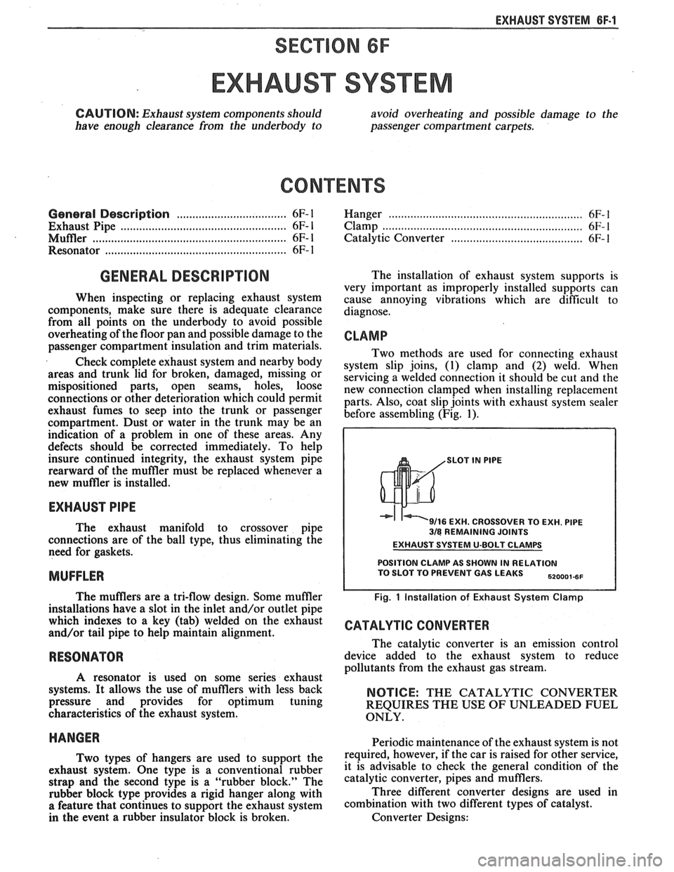
CLAMP
Two methods are used for connecting exhaust
system slip joins, (1) clamp and
(2) weld. When
servicing a welded connection it should be cut and the
new connection clamped when installing replacement
parts. Also, coat slip joints with exhaust system sealer
before assembling (Fig. 1).
SLOT IN PlPE
9/16 EXH. CROSSOVER TO EXH. PlPE 318 REMAINING JOINTS
EXHAUST SYSTEM U-BOLT CLAMPS
POSITION CLAMP AS SHOWN IN RELATION TO SLOT TO PREVENT GAS LEAKS ,,ooo,.,,
Fig. 1 Installation of Exhaust System Clamp
CATALYTIC CONVERTER
The catalytic converter is an emission control
device added to the exhaust system to reduce
pollutants from the exhaust gas stream.
NOTICE: THE CATALYTIC CONVERTER
REQUIRES THE USE OF UNLEADED FUEL
ONLY.
HANGER Periodic maintenance of the exhaust system is not
T~~ types of hangers are used to support the required, however, if the car is raised for other service,
exhaust system. one type is a conventional rubber it is advisable to check the general condition of the
strap and the second type is a "rubber block." The catalytic converter, pipes and mufflers.
rubber block type provides a rigid hanger along with Three
different converter designs are used in
a feature that continues to support the exhaust system combination with two different types of catalyst.
in the event a rubber insulator block is broken. Converter Designs:
Page 987 of 1825
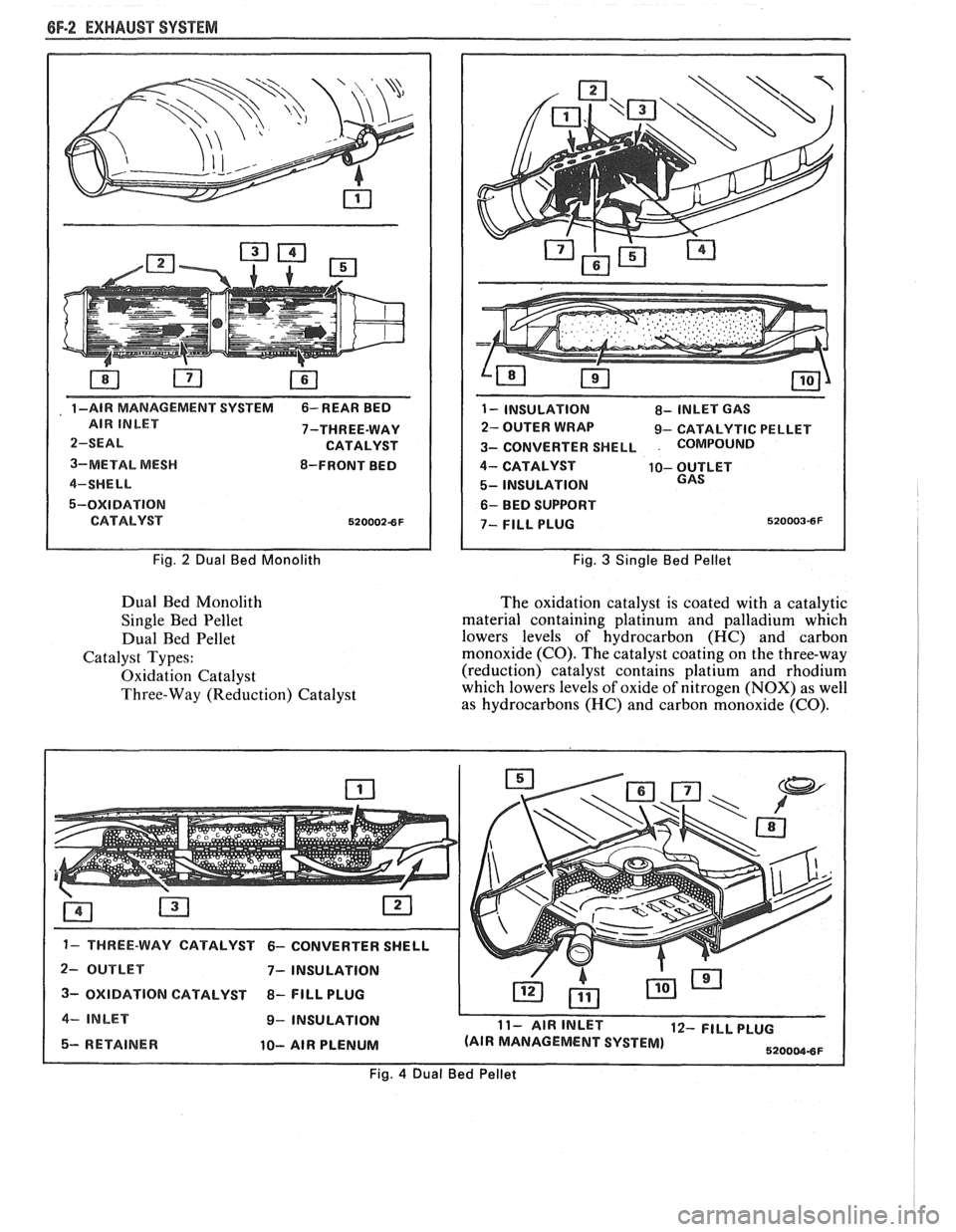
6F-2 EXHAUST SYSTEM
, 1 -AIR MANAGEMENT SVSTEM 6- REAR BED
7-THREE-WAY
3-METAL
MESH 8-FRONT BED
5-OXIDATION
Fig. 2 Dual Bed Monolith
Dual Bed Monolith
Single Bed Pellet
Dual Bed Pellet
Catalyst Types:
Oxidation Catalyst
Three-Way (Reduction) Catalyst
1 - INSULATION 8- INLET GAS
2- OUTER WRAP 9- CATALYTIC PELLET
3- CONVERTER SHELL
. COMPoIJND
4- CATALYST 10- OUTLET
5- INSULATION
6- BED SUPPORT
Fig. 3 Single Bed Pellet
The oxidation catalyst is coated with a catalytic
material containing platinum and palladium which
lowers levels of hydrocarbon (HC) and carbon
monoxide (CO). The catalyst coating on the three-way
(reduction) catalyst contains platium and rhodium
which lowers levels of oxide of nitrogen (NOX) as well
as hydrocarbons (HC) and carbon monoxide
(CO).
2- OUTLET 7- INSULATION I 3- OXIDATION CATALYST 8- FlLL PLUG I 4- INLET 9- INSULATION L
5- RETAINER 10- AIR PLENUM
11- AIR INLET 12- FILL PLUG
(AIR MANAGEMENT SYSTEM)
5200W8F
Fig. 4 Dual Bed Pellet
Page 1121 of 1825
7A1-2 AUTOMATIC TRANSMISSION ON-VEHICLE SERVICE
Pitting
FLEXPLATE/TORQUE CONVERTER VIBRATION
TEST PROCEDURE
1. Start engine
2. With engine at idle speed and the transmission in
"Park"
(P) or "Neutral" (N), observe vibration.
3. Shut off engine.
Remove or Disconnect
e Flexplate cover attaching bolts
s Flexplate to torque converter attaching
bolts
e Rotate torque converter 120 (1/3 turn)
Install
or Connect
e Flexplate to torque converter attaching
bolts
- Torque bolts to 47 N.m (35 Ibs. ft.)
s Flexplate cover bolts
- Torque bolts to 6 N-m (53 lbs. in.)
4. Start engine and check for vibration. Repeat this
procedure un
ti1 the best possible balance is
obtained.
NOTICE: Some engine/transmission
combinations cannot be balanced in this manner
due to limited clearances between the torque
converter bolts and engine. Be sure bolts do not
bottom out in lug nuts or the torque converter
cover could be dented and cause internal damage.
FLUID LEAK DIAGNOSIS
The cause of most external leaks can generally be
located and repaired with the transmission in the car.
METHODS FOR LOCATING LEAKS
General Method
s Verify that the leak is transmission fluid.
a Thoroughly clean the suspected leak area.
s Operate the car for about 15 miles or until normal
operating temperatures are reached.
e Park the car over clean paper or cardboard.
s Shut off engine and look for fluid spots on paper.
a Make necessary repairs.
Powder Method
e Thoroughly clean the suspected leak area with
solvent.
a Apply an aerosol type powder (foot powder) to
the suspected leak area.
s Operate the car for about 15 miles or until normal
operating temperatues are reached.
s Shut off engine.
e Inspect suspected leak area and trace the leak
path through the powder to find the source.
a Make necessary repairs.
Dye And Black Light Method
A fluid dye and black light kit is available from
various tool manufacturers.
s Follow the manufacturer's recommendations for
the amount of dye to be used.
a Detect the leak with the black light.
e Correct cause of leak.
REPAIRING THE LEAK
Once the leak has been pinpointed and traced
back to its source, the cause of the leak must be
determined in order for it to be repaired properly. If a
gasket is replaced, but the sealing flange is bent, the
new gasket will not repair the leak. The bent flange
must be repaired also. Before attempting to repair a
leak, check to be sure that the following conditions are
correct as they may cause a leak.
Gaskets
s Fluid level/pressure is too high.
e Plugged vent or drain-back holes.
s Improperly torqued fasteners or dirty/damaged
threads.
a Warped flanges or sealing surface.
e Scratches, burrs or other damage to the sealing
surface.
e Damaged or worn gasket.
e Cracking or porosity of the component.
s Improper sealant used (where applicable).
Seals
e Fluid level/pressure is too high.
a Plugged vent or drain-back holes.
s Damaged seal bore (scratched, burred or nicked).
e Damaged or worn seal.
e Improper installation.
a Cracks in component.
e Manual or output shaft surface scratched, nicked
or damaged.
a Loose or worn bearing causing excess seal wear.
Possible Points of Oil Leak
I. Transmission/Transmission oil pan :
Attaching bolts not correctly torqued
s Improperly installed or damaged gasket
s Oil pan or mounting face not flat
2, Case Leak :
@ Filler pipe "multi-lip seal" damaged or
missing
a Filler pipe bracket mislocated
s T.V. cable "multi-lip" seal missing,
damaged or improperly installed
a Governor cover or "0" ring damaged or
missing
@ Speedometer driven gear/speed sensor seal
damaged
e Manual shaft seal damaged
s Oil cooler connector fittings loose or
damaged