1988 PONTIAC FIERO check engine
[x] Cancel search: check enginePage 750 of 1825
DRIVEABILITY AND EMISSIONS 2.8L (VIN S) 6E3-CZ-15
NOTICE: Before instal ling new idle air control valve
assembly, the position of its pintle
MUST
be checked. If pintle is extended too far,
damage to the assembly may occur.
Measure
@ Distance from gasket mounting surface of IAC
valve assembly
(70) to tip of pintle, Dimension
"A" in Figure
C2-19.
Adjust
If distance is greater that 28 mm (1 118 in.), reduce -
it as follows:
a. If
IAC valve assembly has
a "collar" around
electrical connector end, use firm hand pressure
on pintle to retract it. (A slight side-to-side motion
may help.)
b. If IAC valve assembly has "no collar", compress
pintle-retaining spring toward body of the IAC
and try to turn pintle clockwise.
@ If pintle will turn, continue turning until
28mm
(1 118 in.) is reached. Return spring to
original position, with straight part of spring
end lined up with flat surface under the pintle
head.
@ If pintle will not turn, use firm hand pressure
to retract it.
Install or Connect
1. New IAC valve assembly gasket (71) on IAC valve
assembly
(70).
2. IAC valve assembly in idle airlvacuum signal
housing assembly
(60).
Tighten
IAC valve assembly to 18N.m (13 ft. Ibs.), with
wrench on hex surface only.
3. Electrical connector at IAC valve assembly (70).
Important
No physical adjustment is made to the IAC
assembly after installation.
IAC resetting occurs
after reinstallation on the vehicle, and is reset
after the engine is started and then the ignition
turned off.
IDLE AIR / VACUUM SIGNAL HOUSING
ASSEMBLY
(With
IAC Removed) (Figure C2-20)
Remove or Disconnect
1. Idle airlvacuurn signal assembly attaching screw
assemblies
(65) and (66).
2. Idle airlvacuum signal housing assembly (60).
3. Idle airlvacuum signal assembly gasket (67).
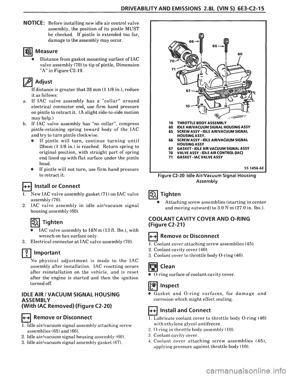
10 THROTTLE BODY ASSEMBLY
60 IDLE AIWVACUUM SIGNAL
HOUSING ASSY
65 SCREW ASSY - IDLE AIWVACUUM SIGNAL
HOUSING ASSY.
66 SCREW
ASSY
- IDLE AIWVACUUM SIGNAL
HOUSING ASSY
67 GASKET - IDLE AIR VACUUM SIGNAL ASSY 70 VALVE ASSY - IDLE AIR CONTROL (IAC) 71 GASKET - IAC VALVE ASSY
Figure C2-20 Idle AirIVacuum Signal Housing
Assembly
Tighten
@ Attaching screw assemblies (starting in center
and
moving outward) to 3.0 N.m (27.0 in. Ibs.).
COOLANT CAVITY COVER AND O-RING
(Figure
C2-21)
Remove or Disconnect
1. Coolant cover attaching. screw assemblies (45).
2. Coolant cavity cover (40).
3. Coolant cover to throttle body O-ring (46).
Inspect
@ Gasket and O-ring surfaces, for damage and
corrosion which might effect sealing.
Install and Connect
1. Lubricate coolant cover to throttle body O-ring (46)
with ethylene glycol antifreeze.
2. O-ring in throttle body assembly (10).
:3. Coolant cavity cover.
4. Coolant cover attaching screw assemblies (451,
applying pressure against throttle body (1 0).
Page 752 of 1825
DRIVEABILITY AND EMISSIONS 2.8L (VIN 5) 6E3-C2-17
FUEL PUMP RELAY
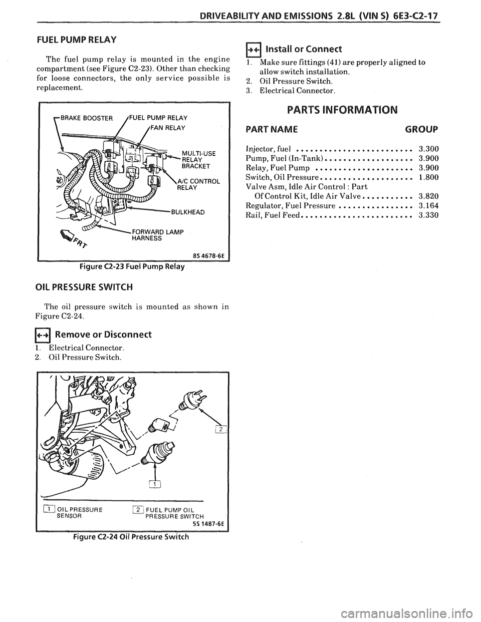
The fuel pump relay is mounted in the engine
compartment (see Figure C2-23). Other than checking
for loose connectors, the only service possible is
replacement.
rBRAKE BOOSTER /FUEL PUMP RELAY
/ /FAN RELAY
RELAY
Y '"ccONT"L
BULKHEAD
FORWARD
LAMP HARNESS
Figure C2-23 Fuel Pump Relay
OIL PRESSURE SWITCH
The oil pressure switch is mounted as shown in
Figure C2-24.
Remove or Disconnect
1. Electrical Connector.
2. Oil Pressure Switch.
Install or Connect
1. Make sure fittings (41) are properly aligned to
allow switch installation.
2. Oil Pressure Switch.
3. Electrical Connector.
PARTS INFORMATION
PART NAME GROUP
Injector, fuel ......................... 3.300
Pump, Fuel (In-Tank)
................... 3.900
Relay, Fuel Pump
..................... 3.900
Switch, Oil Pressure.
................... 1.800
Valve Asm, Idle Air Control
: Part
Of Control Kit, Idle Air Valve.
.......... 3.820
Regulator, Fuel Pressure
................ 3.164
Rail, Fuel Feed. ....................... 3.330
PRESSURE SWI
Figure C2-24 Oil Pressure Switch
Page 755 of 1825
6E3-C2-20 2.8L (VIN S) DRIVEABILITY AND EMISSIONS
AIR THROTTLE FLOW BODY
LD START VALVE
8-5 BLUNVHT
BLUIBLK
GRMNVHT
. GRNIBLK
ECM
.
IAC COIL
"A" HI
IAC COIL "A" LO
IAC COIL "B" HI
C3 IAC COIL "B" LO
7-1 6-87
55 1800-6E
CHART C-2C
IDLE AIR CONTROL
2.8L (VIN S) ""F-SERIES (PORT)
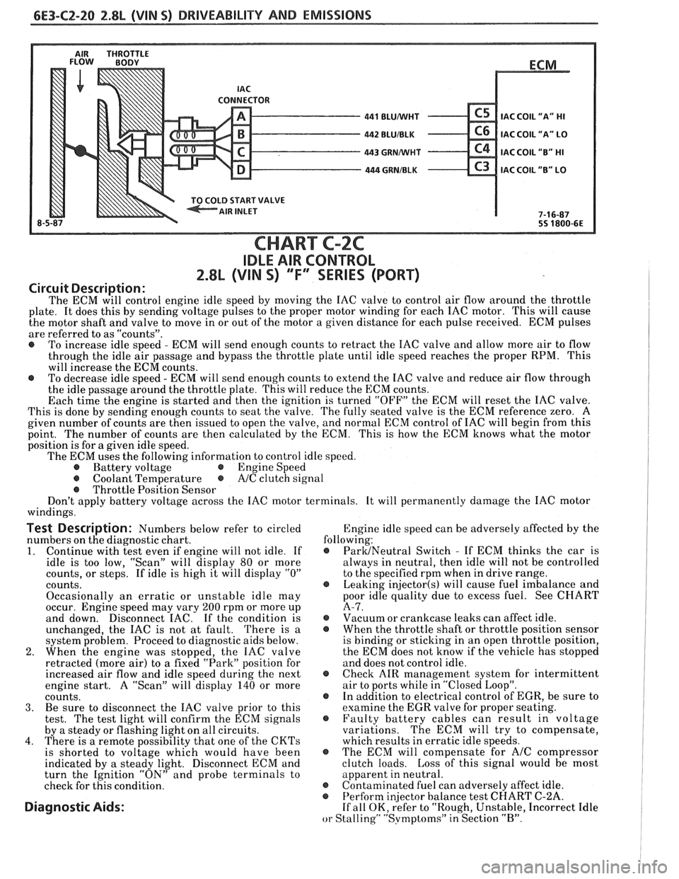
Circuit Description:
The ECM will control engine idle speed by moving the IAC valve to control air flow around the throttle
plate. It does this by sending voltage pulses to the proper motor winding for each IAC motor. This will cause
the motor shaft and valve to move in or out of the motor a given distance for each pulse received. ECM pulses
are referred to as "counts".
@ To increase idle speed - ECM will send enough counts to retract the IAC valve and allow more air to flow
through the idle air passage and bypass the throttle plate until idle speed reaches the proper RPM. This
will increase the ECM counts.
@ To decrease idle speed - ECM will send enough counts to extend the IAC valve and reduce air flow through
the idle passage around the throttle plate. This will reduce the ECM counts.
Each time the engine is started and then the ignition is turned "OFF" the ECM will reset the IAC valve.
This is done by sending enough counts to seat the valve. The fully seated valve is the ECM reference zero. A
given number of counts are then issued to open the valve, and normal ECM control of IAC will begin from this
point. The
number of counts are then calculated by the ECM. This is how the ECM knows what the motor
position is for
a given idle speed.
The ECM uses the following information to control idle speed.
@ Battery voltage @ Engine Speed
@ Coolant Temperature @ A/C clutch signal
@ Throttle Position Sensor
Don't apply battery voltage across the IAC motor terminals. It will permanently damage the IAC motor
windings.
Test Description: Numbers below refer to circled Engine
idle speed can be adversely affected by the
numbers on the diagnostic chart. following:
1. Continue
with test even if engine will not idle. If @ ParUNeutral Switch - If ECM thinks the car is
idle is too low, "Scan" will display
80 or more always
in neutral, then idle will not be controlled
counts, or steps. If idle is high it will display
"0" to the specified rpm when in drive range.
counts.
@ Leaking injector(s) will cause fuel imbalance and
Occasionally an erratic or unstable idle may poor
idle quality due to excess fuel. See CHART
occur. Engine speed may vary
200 rpm or more up A-7.
and down. Disconnect
EAC. If the condition is @ Vacuum or crankcase leaks can affect idle.
unchanged, the IAC is not at fault. There is
a @ When the throttle shaft or throttle position sensor
system problem. Proceed to diagnostic aids below. is
binding or sticking in an open throttle position,
2. When the engine was stopped, the IAC valve the
ECM does not know if the vehicle has stopped
retracted (more air) to a fixed "Park" position for and does not control idle.
increased air flow and idle speed during the next
@ Check AIR management system for intermittent
engine start. A "Scan" will display
140 or more air
to ports while in "Closed Loop".
counts. @ In addition to electrical control of EGR, be sure to
3. Be sure to disconnect the IAC valve prior to this examine the
EGR valve for proper seating.
test. The test light will confirm the ECM signals @ Faulty battery cables can result in voltage
by a steady or flashing light on all circuits. variations. The
ECM will try to compensate,
4. There is a remote possibility that one of the CKTs which results in erratic idle speeds.
is shorted to voltage which would have been @ The ECM will compensate for A/C compressor
indicated by a steady light. Disconnect ECM and clutch
loads. Loss of this signal would be most
turn the Ignition "ON" and probe terminals to apparent
in neutral.
check for this condition.
@ Contaminated fuel can adversely affect idle. @ Perform in
or Stalling" "Svmptoms" in Section "B".
Page 758 of 1825
DRIVEABILITY AND EMISSIONS 2.8L (VIN 5) 6E3-C3-1
SECTION C3
EVAPORATIVE EMlSSlON CON"TOL SYSTEM (EECS)
CONTENTS
GENERAL DESCRIPTION ............... C3-1 DIAGNOSIS ........................ C3-2
PURPOSE ........................ C3-1 VISUAL CHECK OF CANISTER .......... 63-2
VAPOR CANISTER ................... C3-1 FUNCTIONAL TEST
EVAPORATIVE EMISSION SYSTEM
...... C3-1 Vapor Canister Purge Valve ........ C3-2
TANK PRESSURE CONTROLVALVE ...... C3-2 Fuel Tank Pressure Control Valve ..... C3-2
RESULTS OF INCORRECT OPERATION .... C3-2 ON-CAR SERVICE .......*+........ C3-3
FUEL VAPOR CANISTER R/R ............ C3-3
FUEL VAPOR CANISTER SOLENOID RIR.. .. C3-3
CANISTERHOSES.................... C3-3
................ PARTS INFORMATION C3-3
GENERAL DESCRIPTION
PURPOSE
The basic Evaporative Emission Control System
(EECS) used on all vehicles is the charcoal canister
storage method. This method transfers fuel vapor from
the fuel tank to an activated carbon (charcoal) storage
device (canister) to hold the vapors when the vehicle is
not operating. When the engine is running, the fuel
vapor is purged from the carbon element by intake air
flow and consumed in the normal combustion process.
VAPOR CANISTER
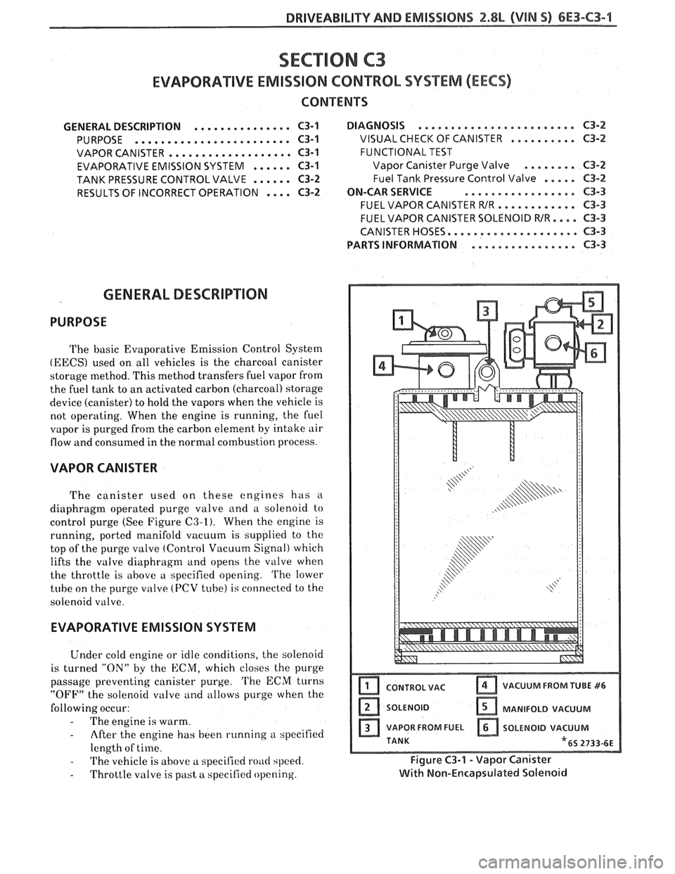
The canister used on these engines has a
diaphragm operated purge valve and a solenoid to
control purge (See Figure
C3-I). When the engine is
running, ported manifold vacuum is supplied to the
top of the
purge valve (Control Vacuum Signal) which
lifts the valve
diaphragm and opens the valve when
the throttle is above a specified opening.
The lower
tube on the purge
valve (PCV tube) is connected to the
solenoid valve.
EVAPORATIVE EMISSION SYSTEM
Under cold engine or idle conditions, the solenoid
is turned
"ON" by the ECM, which closes the purge
passage preventing canister purge.
'L'he ECM turns
"OFF" the solenoid valve and allows purge when the
following occur:
- 'I'he engine is warm.
- After the engine has been running a specified
length of time.
- 'I'he vehicle is above a specified road speed.
- Throttle valve is past a specified opening.
I CONTROL VAC Ifj VACUUM FROM TUBE #6
SOLENOID [ZI MANIFOLD VACUUM
a VAPOR FROM FUEL a SOLENOID VACUUM
TANK
"6s 2733-6E
Fiqure C3-1 - Vapor Canister
with Non-~nca~silated Solenoid
Page 759 of 1825
6E3-C3-2 2.8L (VIN S) DRIVEABILITY AND EMISSIONS
The "CONTROL VAC" tube on the purge valve of the
canister is connected to a ported vacuum source.
When the engine is above idle speed, sufficient
vacuum is available to open the purge valve
diaphragm. Vapors are purge through the solenoid to
the combustion chamber.
This system also has a Tank Pressure Control
Valve to control the flow of vapors to the canister.
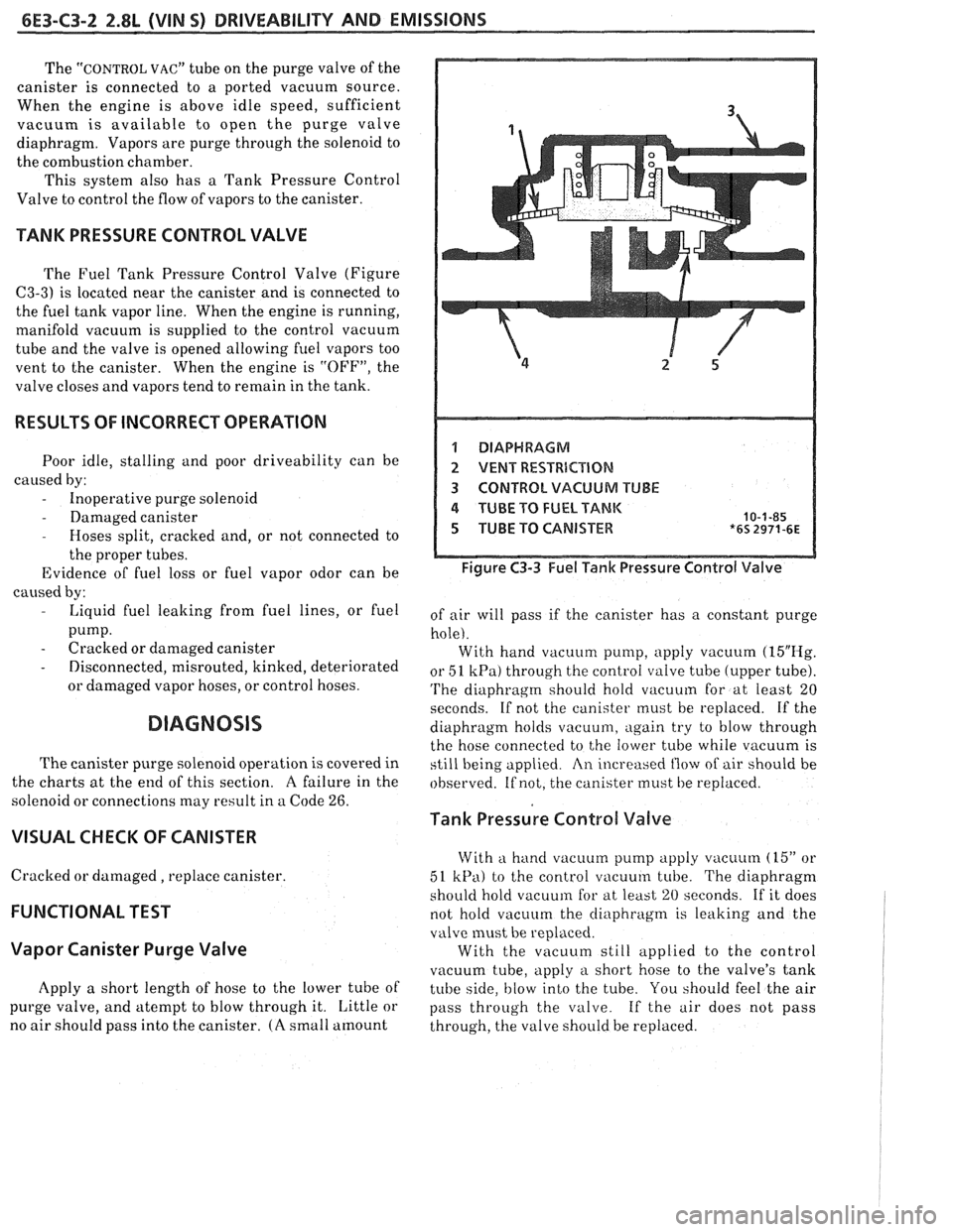
TANK PRESSURE CONTROL VALVE
The Fuel Tank Pressure Control Valve (Figure
C3-3) is located near the canister and is connected to
the fuel tank vapor line. When the engine is running,
manifold vacuum is supplied to the control vacuum
tube and the valve is opened allowing
fuel vapors too
vent to the canister. When the engine is "OFF", the
valve closes and vapors tend to remain in the tank.
RESULTS OF INCORRECT OPERATION
Poor idle, stalling and poor driveability can be
caused by:
- Inoperative purge solenoid
- Damaged canister - Hoses split, cracked and, or not connected to
the proper tubes.
Evidence of fuel loss or fuel vapor odor can be
caused by:
- Liquid fuel leaking from fuel lines, or fuel
pump.
- Cracked or damaged canister
- Disconnected, misrouted, kinked, deteriorated
or damaged vapor hoses, or control hoses.
DIAGNOSIS
The canister purge solenoid operation is covered in
the charts
at the end of this section. A failure in the
solenoid or connections may result in a Code
26.
VISUAL CHECK OF CANISTER
Cracked or damaged, replace canister.
FUNCTIONAL TEST
Vapor Canister Purge Valve
Apply a short length of hose to the lower tube of
purge valve, and atempt to blow through it. Little or
no air should pass into the canister.
(A small amount
1 DIAPHRAGM
2 VENT RESTRBCBIQN
3 CONTROL VACUUM TUBE
4 TUBE TO FUEL TANK 10-1-85 5 TUBE TO CANISTER *6s 2971-6~
Figure C3-3 Fuel Tank Pressure Control Valve
of air will pass if the canister has a constant purge
hole). With hand vacuum pump, apply vacuum
(15"E-Ig.
or 51 kPa) through the control valve tube (upper tube).
'I'he diaphragm should hold vacuum for at least 20
seconds. If not the canister must be replaced. If the
diaphragm holds
vacuu111, again try to blow through
the hose connected to the lower tube while vacuum is
still being applied
An increased flow of air should be
observed. If not, the canister must be replaced.
Tank Pressure Control Valve
With a hand vacuum pump apply vacuum (15" or
51
kPa) to the control vacuum tube. The diaphragm
shoi~ld hold vacuum for at least 20 seconds. If it does
not hold vacuum the
cliaphragnl is leaking and the
valve must be replaced.
With the vacuum still applied to the control
vacuum tube, apply
a short hose to the valve's tank
tube side,
blow into the tube. You should feel the air
pass through the valve. If the
air does not pass
through, the valve should be replaced.
Page 761 of 1825
6E3-C3-4 2.8L (VIN S) DRIVEABILITY AND EMISSIONS
TO CANISTER
I.P. HARNESS CONNECTOR (FRONT VIEW)
428 DK GRNNEL
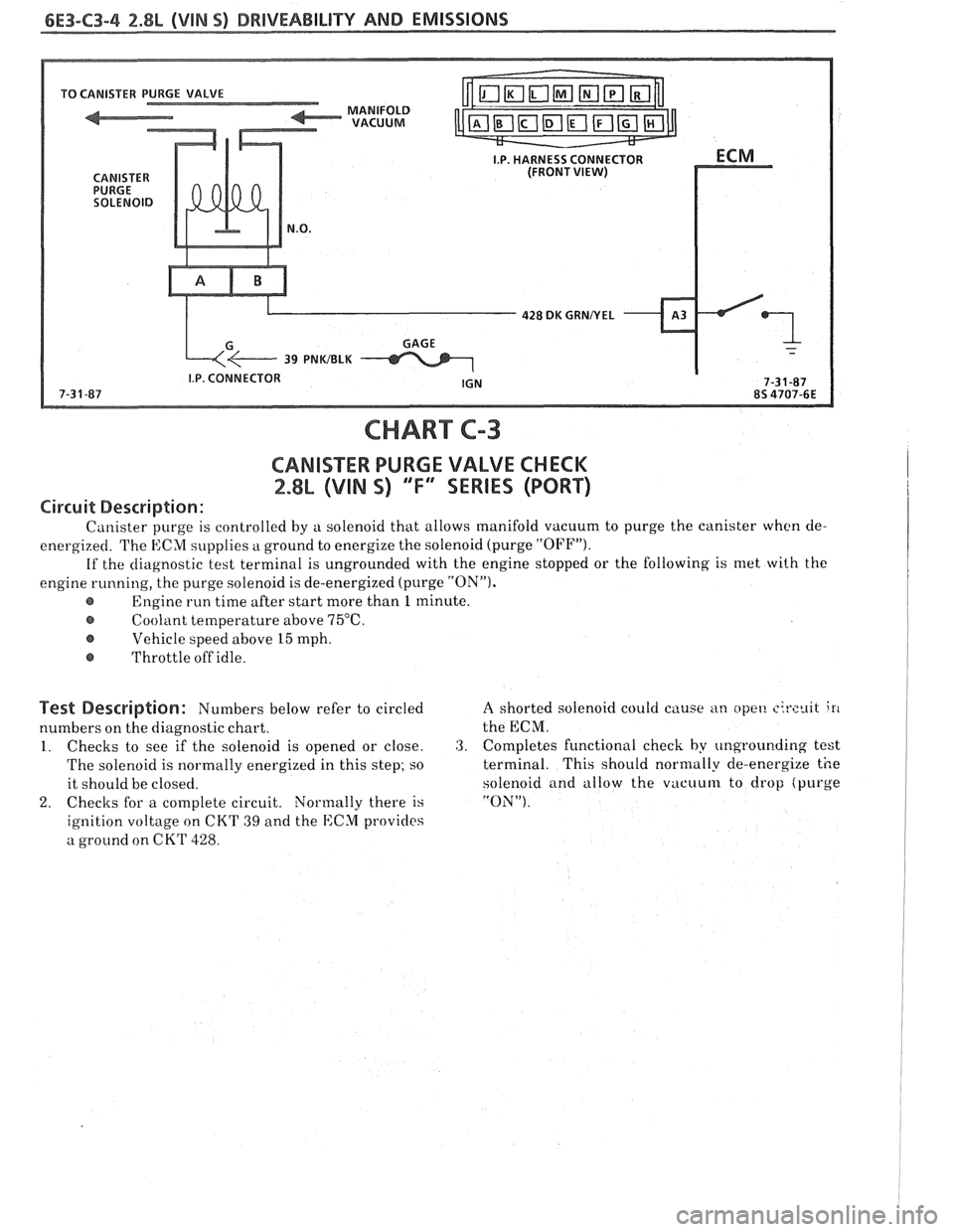
CHART C-3
CARIISXE PURGE VALVE CHECK
2.88 (VIN S) ""F4 SERIES (PORT)
Circuit Description:
Canister purge is controlled by a solenoid that allows manifold vacuum to purge the canister when cle-
energized. The ECM supplies
a ground to energize the solenoid (purge "OFFJ').
If the diagnostic test terminal is ungrounded with the engine stopped or the following is met with the
engine running, the purge solenoid is de-energized (purge
"ON").
Engine run time after start more than 1 minute.
@ Coolant temperature above 75°C.
Vehicle speed above 15 mph.
@ Throttle off idle.
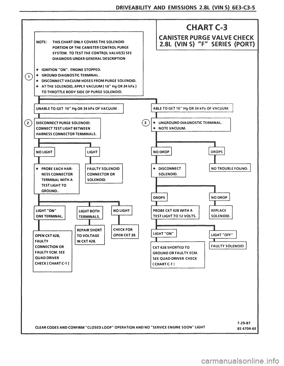
Test Description: Numbers below refer to circled
numbers on the diagnostic chart.
1. Checks to see if the solenoid is opened or close.
The solenoid is normally energized in this step;
so
it should be closed.
2. Checks for a complete circuit. Normally there is
ignition voltage on CKT
39 and the ECM provicles
a ground on CKT
428.
A shorted solenoid could cause an opet! circuit i11
the ECM.
3. Completes functional check by ungrounding test
terminal. This should normally de-energize the
solenoid
and allow the vacuum to drop (purge
"ON").
Page 762 of 1825
DRIVEABILITY AND EMISSIONS f.8L (VIN 5) 6E3-C3-5
NOTE: THIS CHART ONLY COVERS THE SOLENOID
PORTION OF THE CANISTER CONTROL PURGE
SYSTEM. TO TEST THE CONTROL
VALVE(S) SEE
DIAGNOSIS UNDER GENERAL DESCRIPTION
@ IGNITION "ON". ENGINE STOPPED.
@ GROUND DIAGNOSTIC TERMINAL.
AT THE SOLENOID, APPLY VACUUM
( 10" Hg OR 34 kPa )
STIC TERMINAL.
TERMINAL
WITH A
TEST LIGHT TO
CONNECTION OR
FAULTY ECM. SEE
GROUND OR FAULTY ECM.
SEE QUAD DRIVER CHECK
Page 765 of 1825
6E3-C4-2 2.8L (WIN S) DRIVEABILITY AND EMISSIONS
RESULTS OF INCORRECT OPERATION
An open or ground in the EST circuit will set a
Code 42 and cause the engine to run on the HE1
module timing. This will cause reduced performance
and poor fuel economy.
The ECM uses information from the
MAF and
coolant sensors in addition to rpm to calculate spark
~tdvance as follows:
@ Cold engine = more spark advance.
@ Engine under minimum load based on rpm
and low amount of air flow- more spark
advance. Hot engine
= less spark advance.
@ Engine under heavy load based on rprn and
high amount of air flow- less spark advance.
The description, operation, and diagnosis of the
HE1 system are found in Section "GD" of this manual.
CODE 12
Code 12 is used during the Diagnostic Circuit
Check procedure to test the code display ability of the
ECM. This code indicates that the ECM is not
receiving the engine
rpnl (REFERENCE) signal. This
occurs with the ignition key "ON" and the engine not
running.
The "Reference" signal also triggers the fuel
injection system. Without the "Reference" signal the
engine cannot run.
OM-CAR SERVICE
SETTING TIMING
The initial base timing is set by disconnecting the
timing connector, located near the blower motor.
Refer to Emission Control Information Label for
procedure.
This will cause Code 42 to store in the code
memory of the ECM.
The memory must be cleared
after setting timing.
How Code 42 Is Determined
When the system is running on the HE1 module,
that is no voltage on the bypass line, the
HE1 module
grounds the EST signal.
The ECk1 expects to see no
voltage
on the EST line during this condition. If it sees
a voltage, it sets code 42 and will not go into the EST
mode.
When the rpm for EST
is reachecl bout 300 rprn)
the ECM applies 5 volts to the bypass line and the E:SrI'
should no longer be grounded in the tIEI nodule so
the EST voltage should be varying.
If the bypass line is open or grounclecl, the IIEI
tnod~lle will not switch to EST mode so the EST
voltage will be low
and Code 42 will be set. Refer to
Section
"611" for on vehicle service.
PARTS INFORMATION
PART NAME GROUP
Controller, ECM
(Remanufi~ctured) ................ 3.670
.......................... Distributor 2.36 1
Module, Distr ........................ 3.380
........................... Coil, Distr 2.170