1988 PONTIAC FIERO check engine
[x] Cancel search: check enginePage 817 of 1825
6E3-A-14 5.0L (VIN F) & 5.7L (VIN 8) DRIVEABILITY AND EMISSIONS
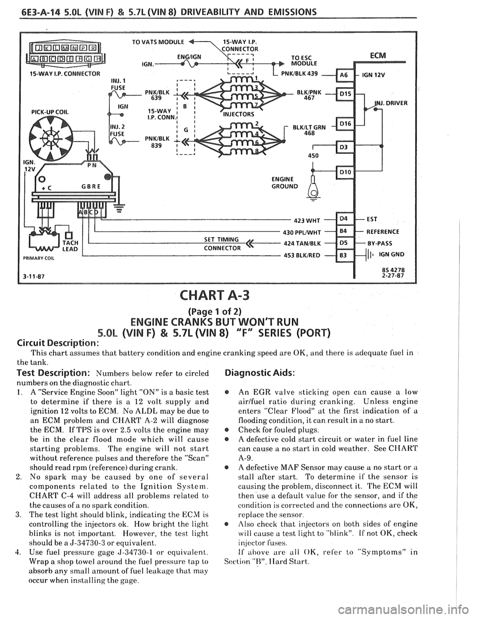
CHART A-3
(Page 1 of 2)
ENGINE CRANKS BUT WON'T RUN
5.OL (VIN F) & 5.7L (VIN 8) "F" SRIES (PORT)
Circuit Description :
This chart assumes that battery condition and engine cranking speed are OK, and there is adequate fuel in
the tank.
Test Description: Numbers below refer to circled Diagnostic Aids:
numbers on the diagnostic chart.
1. A "Service Engine Soon" light "ON" is a basic test @ An EGR valve sticking open can cause a low
to determine if there is a
12 volt supply and airlfuel ratio during cranking. Unless
engine
ignition
12 volts to ECM. No ALDL may be due to enters
"Clear Flood" at the first indication of a
an ECM problem and CHART
A-2 will diagnose flooding
condition, it can result in a no start.
the ECM. If TPS is over
2.5 volts the engine may @ Check for fouled plugs.
be in the clear flood mode which will cause
@ A defective cold start circuit or water in fuel line
starting problems. The engine
will not start can
cause a no start in cold weather. See
CHART
without reference pulses and therefore the "Scan" A-9.
should read rpm (reference) during crank. @ A defective MAF Sensor may cause a no start or a
2. No spark may be caused by one of several stall
after start. To determine if the sensor is
components related to the Ignition System. causing
the problem, disconnect it. The
ECM will
CHART C-4 will address all problems related to then
use a default value for the sensor, and if the
the causes of a no spark condition. condition
is corrected and the connections are
OK,
3. The test light should blink, indicating the ECM is replace the sensor.
controlling the injectors ok. How bright the light
@ rllso check that injectors on both sides of engine
blinks is not important. However, the test light
will cause a test light to "blink". If not OK, check
should be a
5-34730-3 or equivalent. injector fuses.
4. Use fuel
pressure gage 5-34730-1 or equivalent. If al~ove are all OK, refer to "Symptoms" it1
Wrap a shop towel around the fuel pressure tap to Scction "R". Ilard Start.
absorb any small amount of fuel leakage that may
occur when installing the gage.
Page 819 of 1825
6E3-A-16 S.OL (VIN F) & 5.7L(VIN 8) DRIVEABILITY AND EMISSIONS
430 PPWHT
PRIMARY COIL
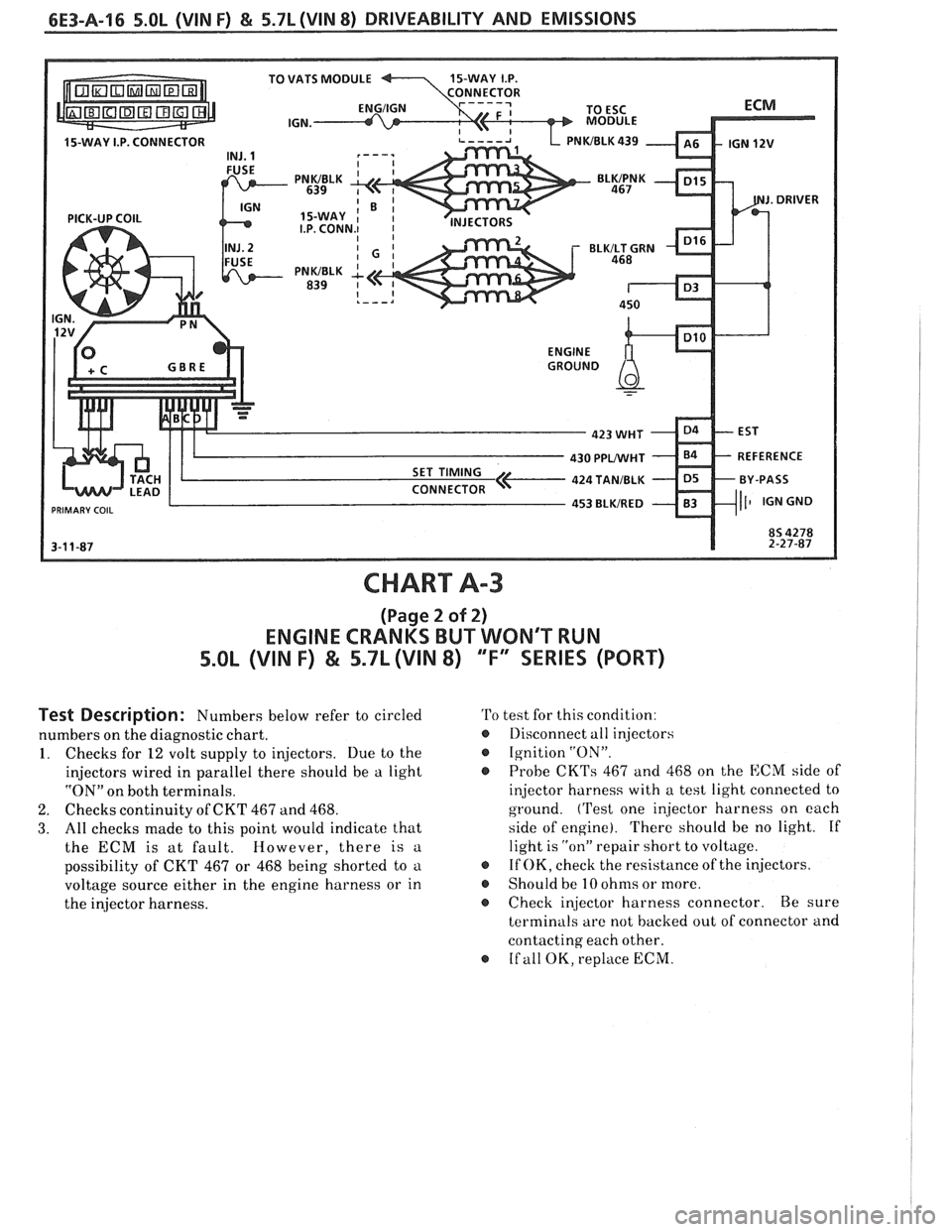
CHART A-3
(Page 2 of 2)
ENGINE CRANKS BUT WONT RUN
5.OL (VIN F) & 5.71 (VIN 8) "F" SERIES (PORT)
Test Description: Numbers below refer to circled
numbers on the diagnostic chart.
1. Checks for 12 volt supply to injectors. Due to the
injectors wired in parallel there should be a light
"ON" on both terminals.
2. Checks continuity of CKT 467 and 468.
3. All checks made to this point would indicate that
the ECM is at fault. However, there is a
possibility of CKT 467 or 468 being shorted to a
voltage source either in the engine harness or in
the injector harness.
'Po test for this condition:
@ Llisconnect all injectors
Ignition
"ON".
@ Probe CKTs 467 and 468 on the ECM side of
injector harness with a test light connected to
ground.
('rest one injector harness on each
side of engine). There should be no light. If
light is
"on" repair short to voltage.
If OK, check the resistance of the injectors.
o Should be 10 ohms or more.
s Check injector harness connector. Be sure
terminals are not backed out of connector and
contacting each other.
o If all OK, replace ECM.
Page 821 of 1825
6E3-A-18 5.OL (WIN F) & 5.7L(VIN 8) DRIVEABILITY AND EMISSIONS
PRESSURE REGULATOR
COLD START
TUBE ASSEMBLY
FUEL PRESSURE
LINE
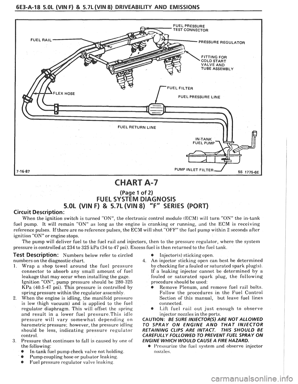
CHART A-7
(Page 1 of 2)
FUEL SYSTEM DIAGNOSIS
5.OL (VIN F) & 5.7L (VIN 8) 'TF'3SERlES (PORT)
Circuit Description:
When the ignition switch is turned "ON", the electronic control module (ECM) will turn "ON" the in-tank
fuel pump. It will remain "ON" as long as the engine is cranking or running, and the
ECM is receiving
reference pulses. If there are no reference pulses, the ECM will shut "OFF" the fuel pump within 2 seconds after
ignition "ON" or engine stops.
The pump will deliver fuel to the fuel rail and injectors, then to the pressure regulator, where the system
pressure is controlled at 234 to 325
kPa (34 to 47 psi). Excess fuel is then returned to the fuel tank.
Test Description: Numbers below refer to circled
numbers on the diagnostic chart.
1. Wrap a shop towel around the fuel pressure
connector to absorb any small amount of fuel
leakage that may occur when installing the gage.
Ignition "ON", pump pressure should be 280-325
KPa (40.5-47 psi). This pressure is controlled by
spring pressure within the regulator
assenlbly
2. When the engine is idling, the manifold pressure
is low (high vacuum) and is applied to the fuel
regulator diaphragm. This will offset
the spring
and result in a lower fuel
pressure.This idle
pressure will vary somewhat depending on
barometric pressure; however, the pressure idling
should be less, indicating pressure regulator
control.
3. Pressure that continues to fall is caused by one of
the following:
In-tank fuel pump check valve not holding.
@ Pump coupling hose or pulsator leaking
@ Fuel pressure regulator valve leaking
Injector(s) sticking open.
4. An
injector sticking open can best be determined
by checking for a fouled or saturated spark
plug(s).
If a leaking injector cannot be determined by a
fouled or saturated spark plug, the following
procedure should be used:
@ Remove Plenum, and remove fuel rail bolts.
Follow the procedures in the Fuel Control
Section of this manual, but leave fuel lines
connected.
s Lift fuel rail out just enough to observe
injector nozzles in the ports.
CAUTION: BE SURE INJECTOR(S) ARE NOT ALLOWED
TO SPRAY ON ENGINE AND THAT INJECTOR
RETAINING CLIPS ARE INTACT.
THIS SHOULD BE
CAREFULLY FOLLOWED TO PREVENT FUEL SPRAY ON
ENGINE WHICH WOULD CAUSE A
FIRE HAZARD.
@ Pressurize the fuel syste~rl and observe injector
nozzles.
Page 827 of 1825
6E3-A-24 5.OL (VIN F) & 5.71 (VIN 8) DRIVEABILITY AND EMISSIONS
OXYGEN ( 02) SENSOR
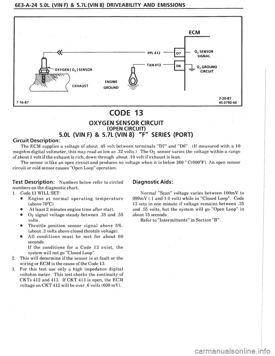
CODE 13
OXYGEN SENSOR CIRCUIT
(OPEN CIRCUIT)
5.OL (VIN F) & 5.7L (VIN 8) 'T" SERIES (PORT)
Circuit Description:
The ECM supplies a voltage of about .45 volt between terminals "D7" and "D6". (If measured with a 10
megohm digital voltmeter, this may read as low as .32 volts.) The
O2 sensor varies the voltage within a range
of about 1 volt if the exhaust is rich, down through about
.l0 volt if exhaust is lean.
The sensor is like an open circuit and produces no voltage when it is below 360
" C(60OoF). An open sensor
circuit or cold sensor causes "Open Loop" operation.
Test Description: Numbers below refer to circled
numbers on the diagnostic chart.
1. Code 13
WILL SET:
@ Engine at normal operating temperature
(above 70°C)
@ At least 2 minutes engine time after start.
@ O2 signal voltage steady between .35 and .55
volts.
@ Throttle position sensor signal above 5%.
(about
.3 volts above closed throttle voltage).
@ All conditions must be met for about 60
seconds. If the conditions for
a Code 13 exist, the
system will not go "Closed Loop".
2. This will determine if the sensor is at fault or the
wiring or ECM is the cause of the Code 13.
3. For this test use only a high impedance digital
voltohm meter. This test checks the continuity of
CKTs 412 and 413. If CKT 413 is open, the ECM
voltage on CKT 412 will be over .6 volts (600 mV).
Diagnostic Aids:
Normal "Scan" voltage varies between 1OOmV to
999mV (.1 and 1.0 volt) while in "Closed Loop". Code
13 sets in one minute if voltage remains between .35
and .55 volts, but the system will go
"Open Loop" in
about
15 seconds.
Refer to "Intermittents" in Section
"B".
Page 829 of 1825
6E3-A-26 5.OL (VIM F) & 5.7L (VIN 8) DRIVEABILITY AND EMISSIONS
COOLANT SENSOR SIGNAL
-
CODE 14
COOLANT TEMPERATURE SENSOR CIRCUIT
(HIGH TEMPERATURE INDICATED)
5.OL (VIN F) & 5.7L (VIN 8) "F"" SERIES (PORT)
Circuit Description:
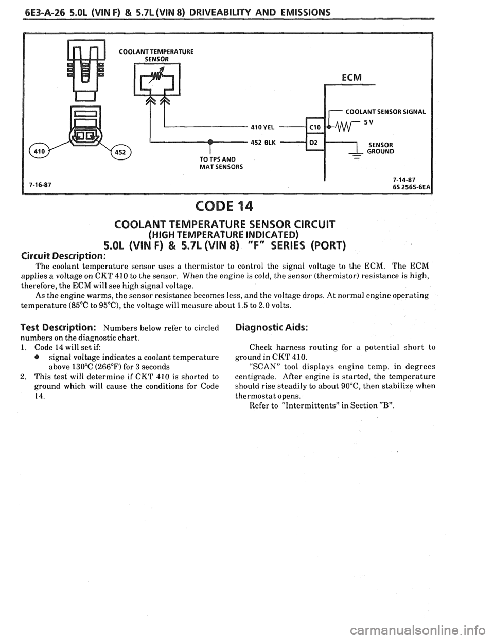
The coolant temperature sensor uses a thermistor to control the signal voltage to the ECM. The ECM
applies a voltage on CKT 410 to the sensor. When the engine is cold, the sensor (thermistor) resistance is high,
therefore, the ECM will see high signal voltage.
As the engine warms, the sensor resistance becomes less, and the voltage drops.
At normal engine operating
temperature
(85°C to 95"C), the voltage will measure about 1.5 to 2.0 volts.
Test Description: Numbers below refer to circled
numbers on the diagnostic chart.
1. Code 14 will set if:
@ signal voltage indicates a coolant temperature
above 130°C (266°F) for
3 seconds
2. This test will determine if CKT 410 is shorted to
ground which will cause the conditions for Code
14.
Diagnostic Aids:
Check harness routing for a potential short to
ground in
CKT 410.
"SCAN" tool displays engine temp, in degrees
centigrade. After engine is started, the temperature
should rise steadily to about
90°C, then stabilize when
thermostat opens.
Refer to "Intermittents" in Section
"B".
Page 831 of 1825
6E3-A-28 S.OL (VIN F) & 5.7L (VIN 8) DRIVEABILITY AND EMISSIONS
COOLANT SENSOR SIGNAL
CODE 15
COOLANT TEMPERATURE SENSOR CIRCUIT
(LOW TEMPERATURE INDICATED)
5.OL (VIN F) & 5.7L (VIN 8) 'Ti' SERIES (PORT)
Circuit Description:
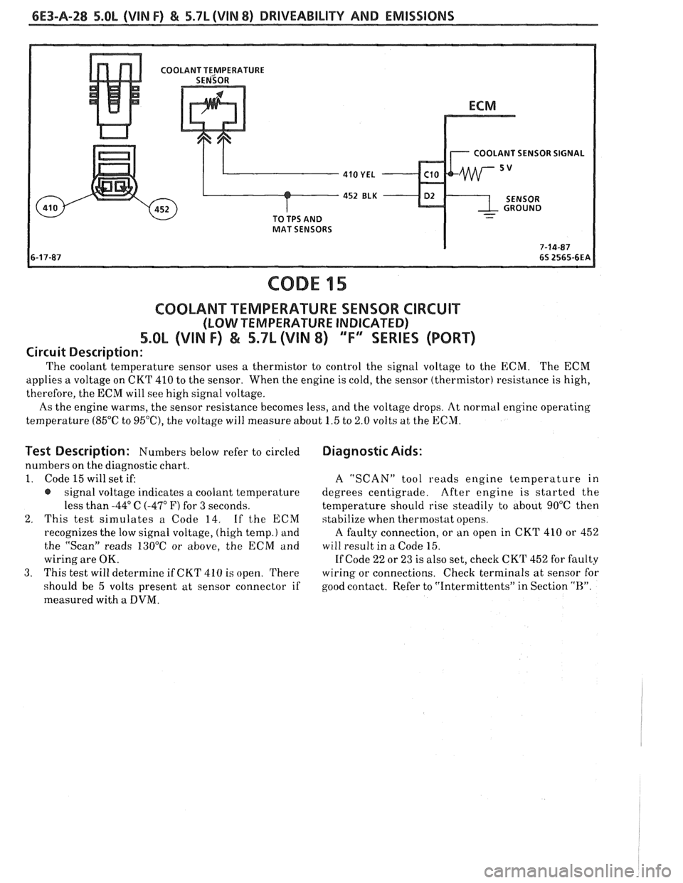
The coolant temperature sensor uses a thermistor to control the signal voltage to the ECM. The ECM
applies a voltage on CKT 410 to the sensor. When the engine is cold, the sensor (thermistor) resistance is high,
therefore, the ECM will see high signal voltage.
As the engine warms, the sensor resistance becomes less, and the voltage drops. At normal engine operating
temperature (85°C to
95'0, the voltage will measure about 1.5 to 2.0 volts at the ECM.
Test Description: Numbers below refer to circled
numbers on the diagnostic chart.
1. Code 15 will set if:
@ signal voltage indicates a coolant temperature
less than
-44" C (-47" F) for 3 seconds.
2. This test simulates a Code 14. If the ECM
recognizes the low signal voltage, (high temp.)
and
the "Scan" reads 130°C or above, the ECM and
wiring are OK.
3. This test will determine if CKT 410 is open. There
should be 5 volts present at sensor connector if
measured with
a DVM.
Diagnostic Aids:
A "SCAN" tool reads engine temperature in
degrees centigrade. After engine is started the
temperature should rise steadily
to about 90°C then
stabilize when thermostat opens.
A faulty connection, or an open in CKT 410 or 452
will result in a Code 15.
If Code 22 or 23 is also set, check CKT 452 for faulty
wiring or connections. Check terminals at sensor for
good contact. Refer to "Intermittents" in Section
"R".
Page 833 of 1825
6E3-A-30 5.OL (VIN F) & 5.7L (VIN 8) DRIVEABILITY AND EMISSIONS
FRONT VIEW TO MAT AND
OF CONNECTOR
COOLANT
452
ELK D2
416 GRY - C14
CODE 21
THROmLE POSITION SENSOR (TPS) CIRCUIT
(SIGNAL VOLTAGE HIGH)
5.OL (VIN I") & 5.7L (VIN 8) 'T" SERIES (PORT)
Circuit Description:
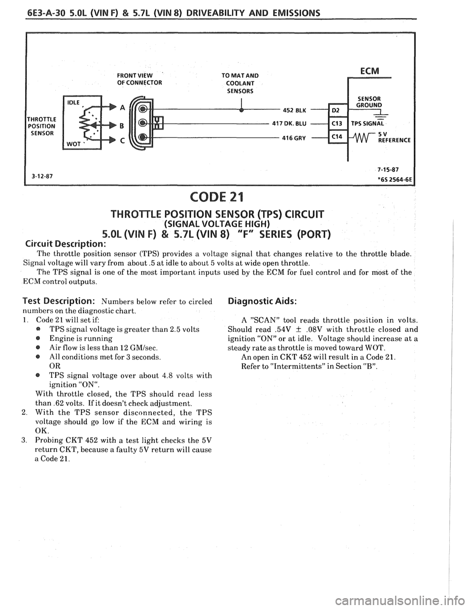
The throttle position sensor (TPS) provides a voltage signal that changes relative to the throttle blade.
Signal voltage will vary from about
.5 at idle to about 5 volts at wide open throttle.
The TPS signal is one of the most important inputs used by the ECM for fuel control and for most of the
ECM control outputs.
Test Description: Numbers below refer to circled
numbers on the diagnostic chart.
1. Code 21 will set if:
@ TPS signal voltage is greater than 2.5 volts
@ Engine is running
@ Air flow is less than 12 GMIsec.
e All conditions met for 3 seconds.
OR
@ TPS signal voltage over about 4.8 volts with
ignition "ON".
With throttle closed, the TPS should read less
than .62 volts. If it doesn't check adjustment.
2. With the TPS sensor disconnected, the TPS
voltage should go low if the ECM and wiring is
OK.
Diagnostic Aids:
A "SCAN" tool reads throttle position in volts.
Should read
.54V f .08V with throttle closed and
ignition "ON" or at idle. Voltage should increase at a
steady rate as throttle is moved toward WOT.
An open in CKT 452 will result in
a Code 21.
Refer to "Intermittents" in Section
"B".
3. Probing CKT 452 with a test light checks the 5V
return CKT, because
a faulty 5V return will cause
a Code 21.
Page 835 of 1825
6E3-A-32 5.OL (VIN F) & 5.7L (VIN 8) DRIVEABILITY AND EMISSIONS
FRONT VIEW TO MAT AND OF CONNECTOR COOLANT
SENSORS
452 BLK - D2 .
416 GUY - C14
CODE 22
THROTLE POSITION SENSOR (WS) CIRCUIT
(SIGNAL VOLTAGE LOW)
5.OL (VIN F) & 5.7L (VIN 8) "F'YSERIES (PORT)
Circuit Description:
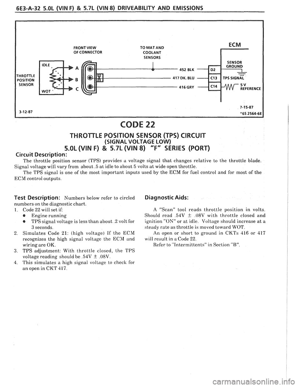
The throttle position sensor (TPS) provides a voltage signal that changes relative to the throttle blade.
Signal voltage will vary from about
.5 at idle to about 5 volts at wide open throttle.
The TPS signal is one of the most important inputs used by the
ECM for fuel control and for most of the
ECM control outputs.
Test Description: Numbers below refer to circled
numbers on the diagnostic chart.
1. Code22willsetiE
@ Engine running
TPS signal voltage is less than about
.% volt for
3 seconds.
2. Simulates
Code
21: (high voltage) If the ECM
recognizes the high signal voltage the ECM and
wiring are
OK.
3. TPS adjustment: With throttle closed, the TPS
voltage reading should be
54V f .08V.
4. This simulates a high signal voltage to check for
an open in CKT
417.
Diagnostic Aids:
A "Scan" tool reads throttle position in volts.
Should read
54V + .08V with throttle closed and
ignition
"ON" or at idle. Voltage should increase at a
steady rate as throttle is moved toward WOT.
An open or short to ground in
CKTs 416 or 417
will result in a Code 22.
Refer to "Intermittents" in Section
"B".