1988 PONTIAC FIERO check engine
[x] Cancel search: check enginePage 726 of 1825
DRIVEABILITY AND EMISSIONS 2.8L (VIN S) 6E3-C1-7
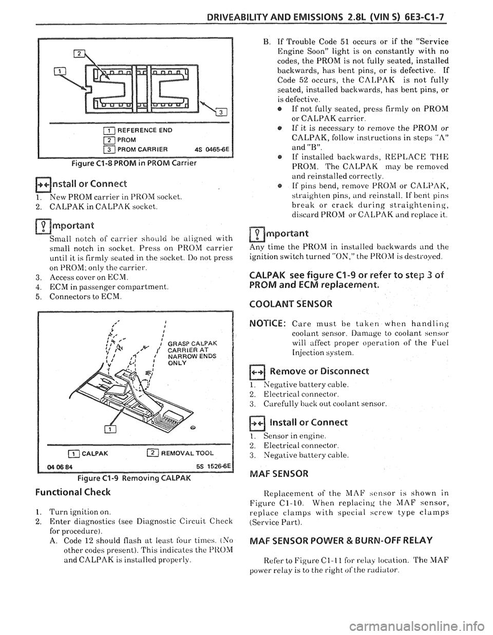
REFERENCE END
PROM PROM CARRIER
4S 81165-6E
Figure C1-8 PROM in PROM Carrier
mnstall or Connect
1. New PROM carrier in PROM socliet.
2. CALPAK in CALPAK socket.
mmportant
Small notch of carrier shoiild he aligned with
small notch in socket. Press on PROM carrier
until it is firmly seated in the socket. Do not press
on PROM; only the carrier.
3. Access cover on ECM.
4. ECRil in passenger compartment.
5. Connectors to ECM.
b A,' I
;,* fd I
: GRASP CALPAK 1% ,/w 1' CARRIERAT
[ZJ REMOVAL TOOL
Figure C1-9 Removing CALPAK
B. If Trouble Code 51 occurs or if the "Service
Engine Soon" light is on constantly with no
codes, the PROM is not fully seated, installed
backwards, has bent pins, or is defective. If
Code
52 occurs, the CALPAK is not fully
seated, installed backwards, has bent pins, or
is defective.
If not fully seated,
press firmly on PROM
or CALPAK carrier
a, If it is necessary to remove the PROM or
CALPAK, follow instructions in steps "A"
and
"B".
@ If installed backwards, REPLACE THE
PROM. The CALPAK may be removed
and reinstalled correctly.
@ If pins bend, remove PROM or CALPAK,
straighten pins, and reinstall. If
bent pins
break or crack during
straightening,
discard PROM or CtILPAK and replace it,.
am port ant
Any time the PROM in installed backwards and the
ignition switch turned
"ON," the f'I
PROM and ECM replacement.
COOLANT SENSOR
NOTICE:
Care must be taken when handling
coolant sensor.
Damage to coolant sensor
will affect proper operation of the Fuel
Injection
system.
B Remove or Disconnect
1. Negative buttery cable.
2.
Electricril connector.
3. Carefully back out coolant sensor.
a ln,aIl
1. Sensor in
or Connect
engine.
2. Electrical connector.
3. Negative battery cable.
MAF SENSOR
Functional Check
Replacement of the iL'IAF xcnsor is shown in
Figure C1-10. When
replacing the MAF sensor,
1. Turn ignition on.
replace cla~llps with special hcrew type cla~rlps
2. Enter diagnostics (see Diagnostic Circuit Check (Service Part).
for procedure).
A. Code 12 should flash at least four times. (Yo MAF SENSOR POWER & BURN-OFF RELAY
other codes present). This indicates the PIIOM
and CALPAK is installed properly.
Refer to Figure C 1- 1 1 for relay location. 'rhe MAF
power relay is to the right ofthe radiator
Page 729 of 1825
6E3-C1-10 2.8L (VIN 5) DRIVEABILITY AND EMISSIONS
- 959 DK GRN
BRAKE SWITCH
MANUALTRANS
TO FAN
CONTROL +-- DK GRNMIHT335 - COOLING FAN
RELAY
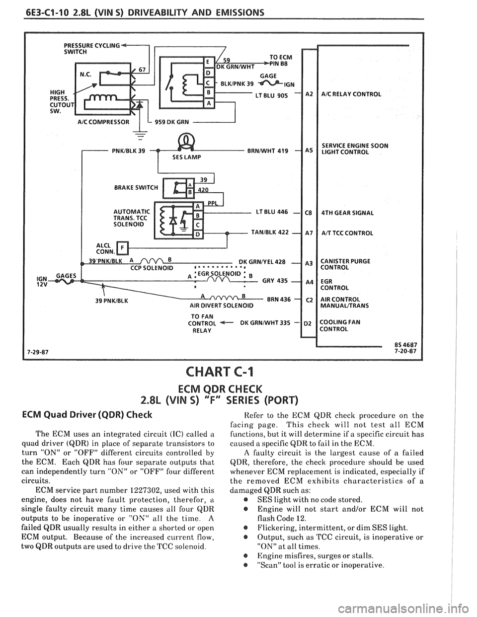
CHART C-I
ECM QDR CHECK
2.8% (VIN S) 'TI' SERIES (PORT)
ECM Quad Driwer (QDR) Check
The ECM uses an integrated circuit (IC) called a
quad driver
(QDR) in place of separate transistors to
turn "ON" or "OFF" different circuits controlled by
the ECM. Each
QDR has four separate outputs that
can independently turn "ON" or "OFF" four different
circuits.
ECM service part number 1227302, used with this
engine, does not have fault protection, therefor,
a
single faulty circuit many time causes all four QDR
outputs to be inoperative or "OX" all the time.
A
failed QDR usually results in either a shorted or open
ECM output. Because of the increased current
flow,
two QDR outputs are used to drive the TCC solenoid. Refer
to the ECM QDR check procedure on the
facing page. This
check will not test all ECM
functions, but it will determine if a specific circuit has
caused a specific
QDR to fail in the ECM.
A faulty circuit is the largest cause of a failed
QDR, therefore, the check procedure should be used
whenever ECM replacement is indicated, especially if
the removed ECM exhibits characteristics of a
damaged QDR such as:
@ SES light with no code stored.
@ Engine will not start and/or ECM will not
flash Code 12.
@ Flickering, intermittent, or dim SES light.
@ Output, such as TCC circuit, is inoperative or
"ON" at all times.
@ ISngine misfires, surges or stalls.
@ "Scan" tool is erratic or inoperative.
Page 731 of 1825
6E3-C1-12 2.8L (VIN 5) DRIVEABILITY AND EMISSIONS
15 WAY. (FRONT VIEW)
434 ORNIBLK
450 BLWHT
ENGINE GROUND
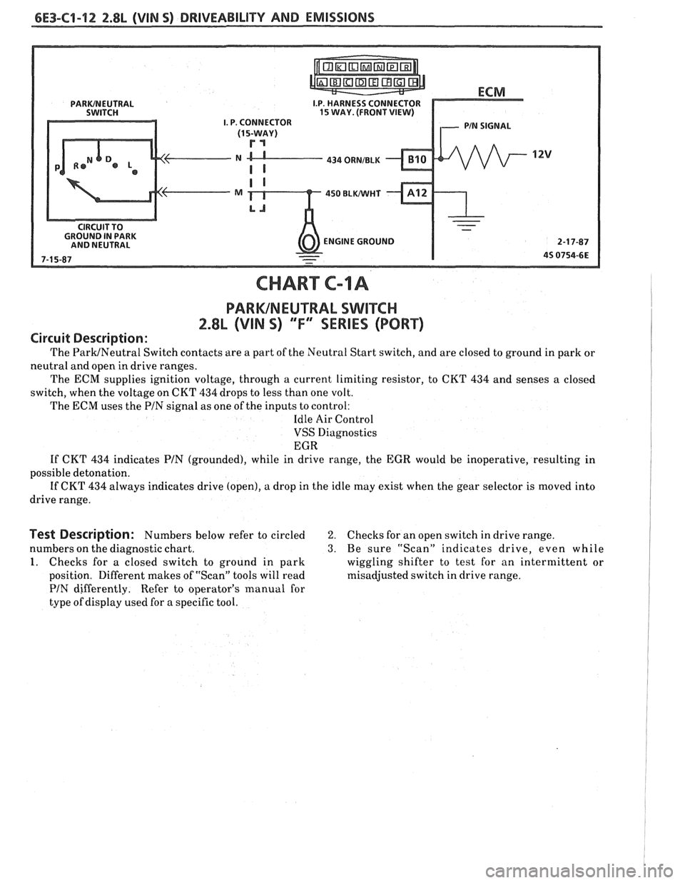
CHART C-IA
PARWNEUTRAL SWITCH
2.8L (VIN S) "F" SERIES (PORT)
Circuit Description:
The ParWNeutral Switch contacts are a part of the Neutral Start switch, and are closed to ground in park or
neutral and open in drive ranges.
The ECM supplies ignition voltage, through a current limiting resistor, to CKT
434 and senses a closed
switch, when the voltage on CKT
434 drops to less than one volt.
The
ECM uses the PIN signal as one of the inputs to control:
Idle Air Control
VSS Diagnostics
EGR
If CKT 434 indicates PIN (grounded), while in drive range, the EGR would be inoperative, resulting in
possible detonation.
If CKT 434 always indicates drive (open), a drop in the idle may exist when the gear selector is moved into
drive range.
Test Description: Numbers below refer to circled 2. Checks for an open switch in drive range.
numbers on the diagnostic chart.
3. Be sure "Scan" indicates drive, even while
1. Checks for a closed switch to ground in park wiggling shifter to test for an intermittent or
position. Different makes of "Scan" tools will read misadjusted switch in drive range.
PIN differently. Refer to operator's manual for
type of display used for a specific tool.
Page 733 of 1825
6E3-C4-14 2.8L (VIN S) BWiVEABlLlPV AND EMISSIONS
POWER STEERING
PRESSURE SWITCH
PIS PRESSURE
CLOSES
WITH HIGH BLWHT
PRESSURE
-
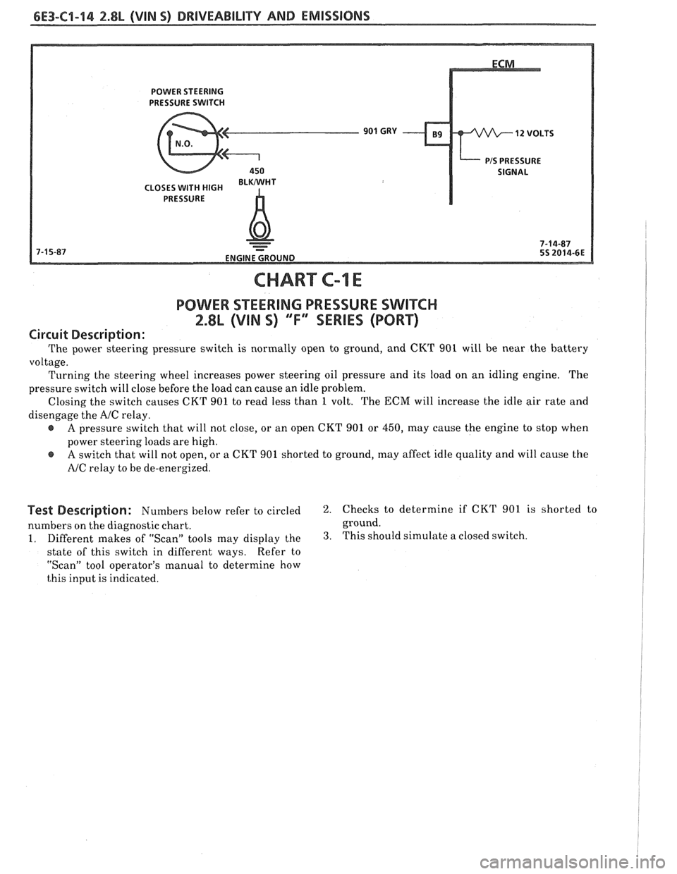
CHART C-1 E
POWER STEERING PRESSURE SWITCH
2.8L (VIN S) "F"" SERIES (PORT)
Circuit Description:
The power steering pressure switch is normally open to ground, and CKT 901 will be near the battery
voltage. Turning the steering wheel increases power steering oil pressure and its load on an idling engine. The
pressure switch will close before the load can cause an idle problem.
Closing the switch causes CKT 901 to read less than
1 volt. The ECM will increase the idle air rate and
disengage the
A/C relay.
e A pressure switch that will not close, or an open CKT 901 or 450, may cause the engine to stop when
power steering loads are high.
@ A switch that will not open, or a CKT 901 shorted to ground, may affect idle quality and will cause the
NC relay to be de-energized.
Bescription: Numbers below refer to circled 2. Checks to determine if CKT 901 is shorted to
numbers on the diagnostic chart. ground.
1. Different makes of "Scan" tools may display the 3. This should simulate
a closed switch.
state of this switch in different ways. Refer
to
"Scan" tool operator's manual to determine how
this input is indicated.
Page 737 of 1825
Starting Mode
When the ignition is first turned "ON," the ECM
will turn "ON" the fuel pump relay for two seconds,
and the fuel pump will build up pressure. The ECM
then checks the coolant temperature sensor, throttle
position sensor, and determines the proper airlfuel
ratio for starting. This ranges from 1.5
: 1 at -36°C (-
33°F ) to 14.7 : 1 at 94°C ( 201°F ). The ECM controls
the amount of fuel delivered in the STARTING mode
by changing how long the injectors are pulsed "ON".
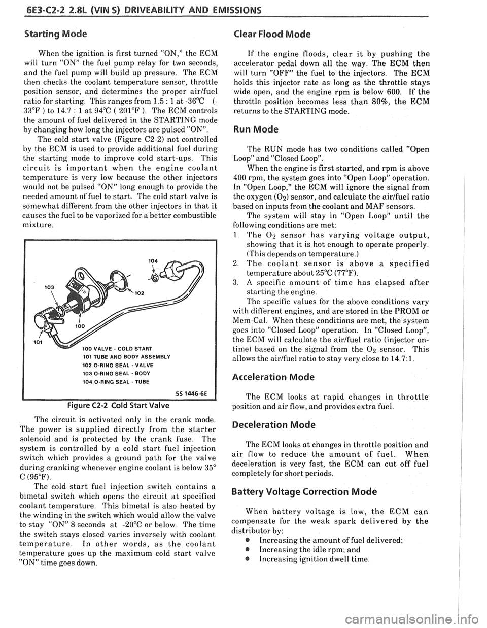
The cold start valve (Figure C2-2) not controlled
by the ECM is used to provide additional fuel during
the starting mode to improve cold start-ups. This
circuit is important when the engine coolant
temperature is very low because the other injectors
would not be pulsed "ON" long enough to provide the
needed amount of fuel to start. The cold start valve is
somewhat different from the other injectors in that it
causes the fuel to be vaporized for a better combustible
mixture.
101 TUBE AND BODY ASSEMBLY
102 O-RING SEAL
- VALVE
103 O-RING SEAL
- BODY
104 O-RING SEAL
- TUBE
Figure C2-2 Cold Start Valve
The circuit is activated only in the crank mode.
The power is supplied directly from the starter
solenoid and is protected by the crank fuse. The
system is controlled by
a cold start fuel injection
switch which provides
a ground path for the valve
during cranking whenever engine coolant is below 35"
C (95°F).
Clear Flood Mode
If the engine floods, clear it by pushing the
accelerator pedal down all the way. The
ECM then
will turn "OFF" the fuel to the injectors. The
ECM
holds this injector rate as long as the throttle stays
wide open, and the engine rpm is below
600. If the
throttle position becomes less than
80%, the ECM
returns to the STARTING mode.
Run Mode
The RUN mode has two conditions called "Open
Loop" and "Closed Loop".
When the engine is first started, and rpm is above
400 rpm, the system goes into "Open Loop" operation.
In "Open Loop," the ECM will ignore the signal from
the oxygen
(02) sensor, and calculate the airlfuel ratio
based on inputs
from the coolant and MAF sensors.
The system will stay in "Open Loop" until the
following conditions are met:
1. The
O2 sensor has varying voltage output,
showing that it is hot enough to operate properly.
(This depends on temperature.)
2. The coolant sensor is above a specified
temperature about 25°C
(77°F).
3. A specific amount of time has elapsed after
starting the engine.
The specific values for the above conditions vary
with different engines, and are stored in the PROM or
Mem-Cal. When these conditions are met, the system
goes into "Closed Loop" operation. In "Closed Loop",
the ECM will calculate the airlfuel ratio (injector on-
time) based on the signal from the
O2 sensor. This
allows the airlfuel ratio to stay very close to 14.7: 1.
Acceleration Mode
The ECM looks at rapid changes in throttle
position and air flow, and provides extra fuel.
Deceleration Mode
The ECM looks at changes in throttle position and
air flow to reduce the amount of fuel. When
deceleration is very fast, the ECM can cut off fuel
completely for short periods.
The cold start fuel injection switch contains a
bimetal switch which opens the circuit at specified
Battery Voltage Correction Mode
coolant temperature. This bimetal is also heated by
the winding in the switch which would allow the valve When battery
voltage is low, the ECM can
to stay "ON" 8 seconds at -20°C or below. The time compensate
for the weak spark delivered by the
the switch stays closed varies inversely with coolant distributor
by:
temperature. In other words, as the coolant
@ Increasing the amount of fuel delivered;
temperature goes up the maximum cold start valve
@ Increasing the idle rpm; and
"ON" time goes down. Increasing ignition
dwell time.
Page 740 of 1825
DRIVEABILITY AND EMISSIONS 2.8L (VIN 5) 6E3-C2-5
As a backup system to the fuel pump relay, the
fuel pump can also be turned "ON" by the oil pressure
switch. The oil pressure switch is a normally open
switch which closes when oil pressure reaches about
28
kPa (4 psi). If the fuel pump relay fails, the oil
pressure switch will close and run the fuel pump.
An inoperative fuel pump relay can result in long
cranking times, particularly if the engine is cold.
An inoperative fuel pump would cause a no start
condition. A fuel pump which does not provide enough
pressure can result in poor performance.
FUEL CONTROL SYSTEM
Some failures of this system will result in an
"Engine Cranks But Won't Run". If
this condition
exists, see CHART A-3. This chart will determine if
the problem is caused by the ignition system, ECM or
fuel pump circuit. If
it's determined to be a fuel
problem, CHART
A-7 will be used. This includes the
injectors, pressure regulator, fuel pump and fuel pump
relay. The fuel system wiring schematic is covered on
the facing page of Code CHART
54.
If a malfunction occurs in the fuel control system
it usually results in either a rich or a lean exhaust
condition. This condition is sensed by the oxygen
sensor and the ECM will change the fuel calculation
(injector pulse width) based on the
02 sensor reading.
The change made to the fuel calculation will be
indicated by a change in the block learn values which
can be monitored by a "Scan" tool. The normal block
learn values are around 128 and if the
O2 sensor is
sensing a lean condition, the ECM will add fuel and
this will result in a block learn value above 128. If the
02 sensor is sensing a rich exhaust the ECM will
reduce fuel to the engine and this will result in block
learn values below 128. Some variations in block
learn values are normal because all engines are not
exactly the same. However, if the block learn values
are
+ 10 counts from 128, a system problem exists. If
the block learn values are greater than 138, see Code
44 for items which can cause a lean system.
If the block learn values are less than 118, see
Code
45 for items which can cause the system to run
rich. If a driveability symptom exists, refer to the
particular symptom in Section
"B" for additional
items to check.
IDLE AIR CONTROL VALVE
A "Scan" tool will read IAC position in steps
(counts).
"0" steps indicates the ECM is commanding
the IAC to be driven all the way in, to a fully seated
position, and this is usually caused by a vacuum leak.
The higher the number of counts the more air being
allowed to pass the IAC valve. CHART C-2C can be
used to diagnosis the IAC valve. Also refer to "Rough, Unstable,
or Incorrect Idle, Stalling" in "Symptoms,"
Section
"B" for other possibilities for the cause of idle
problems.
ON-CAR SERVICE
PORT FUEL INJECTION COMPONENTS
CAUTION:
Before servicing an injector, fuel
rail, or pressure regulator, it is
necessary to relieve the pressure in
the fuel system, to minimize the risk
of fire and personal injury. (See
"Fuel Pressure Relief Procedure"
below). To reduce the chance of
personal injury, cover the fuel line
with a shop cloth to collect the fuel,
and then place the cloth in an
approved container.
FUEL PRESSURE RELIEF PROCEDURE
Connect fuel gage J 34730-1 or equivalent to fuel
pressure valve. Wrap a shop towel around fitting
while connecting gage to avoid spillage.
Install bleed hose into an approved container and
open valve to bleed system pressure.
Plenum
Remove or Disconnect
1. Negative battery cable.
2. Air
inlet duct at throttle body.
3. Throttle body retaining bolts
(2).
4. EGR pipe bolts (2).
5. Throttle cable bracket.
6. Plenum bolts (8).
Install or Connect
I. Plenum and gaskets.
2. Plenum bolts. See Figure C2-6.
3. Throttle cable bracket.
4. EGR pipe bolts.
5. Throttle body and bolts.
6. Air inlet duct
7. Negative battery cable.
Fuel Rail and Pressure Regulator Assembly
Important
When servicing the fuel rail assembly,
precautions must be taken to prevent dirt and
other contaminants from entering the fuel
passages. It is recommended that fittings
he
capped and holes be plugged during servicing.
Page 742 of 1825
DRIVEABILITY AND EMISSIONS 2.8L (VIN S) 6E3-CZ-7
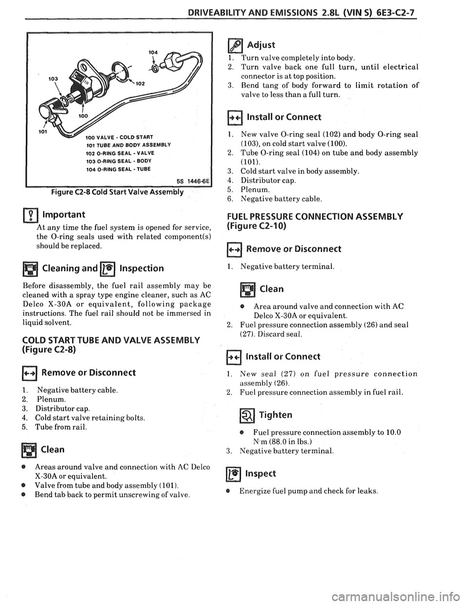
100 VALVE - COLD START
101 TUBE AND BODY ASSEMBLY
102 O-RING SEAL -VALVE
103 O-RING SEAL - BODY
104 O-RING SEAL -TUBE
Figure C2-8 Cold Start Valve Assembly
important
At any time the fuel system is opened for service,
the O-ring seals used with related
component(s)
should be replaced.
a Cleaning and a Inspection
Before disassembly, the fuel rail assembly may be
cleaned with a spray type engine cleaner, such as AC
Delco X-30A or equivalent, following package
instructions. The fuel rail should not be immersed in
liquid solvent.
COLD START TUBE AND VALVE ASSEMBLY
(Figure C2-8)
Remove or Disconnect
1. Negative battery cable.
2. Plenum.
3. Distributor cap.
4. Cold start valve retaining bolts.
5. Tube from rail.
Clean
@ Areas around valve and connection with AC Delco
X-30A or equivalent.
@ Valve from tube and body assembly (101).
@ Bend tab back to permit unscrewing of valve.
@ Adjust
1. Turn valve completely into body.
2. Turn valve back one full turn, until electrical
connector is at top position.
3. Bend tang of body forward to limit rotation of
valve to less than
a full turn.
Install or Connect
1. New valve O-ring seal (102) and body O-ring seal
(103), on cold start valve (100).
2. Tube O-ring seal (104) on tube and body assembly
(101).
3. Cold start valve in body assembly.
4. Distributor cap.
5. Plenum.
6. Negative battery cable.
FUEL PRESSURE CONNECTION ASSEMBLY
(Figure
C2-I 0)
Remove or Disconnect
1. Negative battery terminal.
Clean
@ Area around valve and connection with AC
Delco X-30A or equivalent.
2. Fuel pressure connection assembly (26) and seal
(27). Discard seal.
Install or Connect
1. New seal (27) on fuel pressure connection
assembly
(26).
2. Fuel pressure connection assembly in fuel rail.
Tighten
@ Fuel pressure connection assembly to 10.0
N.m (88.0 in lbs.)
3. Negative battery terminal.
a inspect
@ Energize fuel pump and check for leaks.
Page 744 of 1825
DRIVEABILITY AND EMISSIONS 2.8L (VIN S) 6E3-C2-9
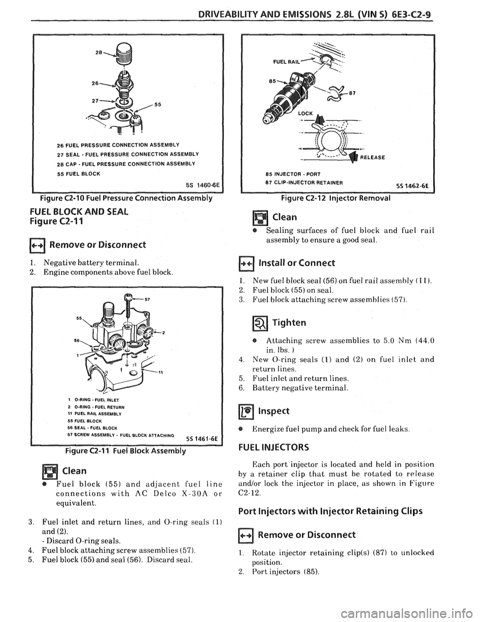
26 FUEL PRESSURE CONNECTION ASSEMBLY
27 SEAL - FUEL PRESSURE CONNECTION ASSEMBLY
28 CAP - FUEL PRESSURE CONNECTION ASSEMBLY
55 FUEL BLOCK
Figure C2-10 Fuel Pressure Connection Assembly
FUEL BLOCK AND SEAL
Figure CZ-I 1
Remove or Disconnect
1. Negative battery terminal.
2. Engine components above fuel block.
I O-RING -FUEL INLET 2 O-RING . FUEL RETURN 11 FUEL RAlL ASSEMBLY 55 FUEL BLOCK 56 SEAL -FUEL BLOCK 57 SCREW ASSEMBLY - FUEL BLOCK ATTACHING 55 1461-6E
Figure C2-11 Fuel Block Assembly
Clean
@ Fuel block (55) and adiacent fuel line
connections with
AC ~elco X-30A or
equivalent.
3. Fuel inlet and return lines, and O-ring seals (1)
and (2).
- Discard O-ring seals.
4. Fuel block attaching screw assemblies
(57).
5. Fuel block (55) and seal (56). Discard seal.
FUEL RAlL
REL
85 INJECTOR -PORT
87 CLIP-INJECTOR RETAINER
Figure C2-12 Injector Removal
- @ Sealing surfaces of fuel block and fuel rail
assembly to ensure a good seal.
Install or Connect
1. New fuel block sea1 (56) on fuel rail assembly ( 1 I).
2. Fuel block (55) on seal.
3. Fuel block attaching screw assemblies (57).
Tighten
@ Attaching screw assemblies to 5.0 Nm (44.0
in. Ibs.
)
4. New O-ring seals (1) and (2) on fuel inlet and
return lines.
5. Fuel inlet and return lines.
6. Battery negative terminal.
Inspect
@ Energize fuel pump and check for fuel leaks
FUEL INJECTORS
Each port injector is located and held in position
by a retainer clip that must be rotated to release
and/or lock the injector in place, as shown in Figure
C2-12.
Port Injectors with lnjector Retaining Clips
Remove or Disconnect
1. Rotate injector retaining clip(s) (87) to unlocked
position.
2. Port in*jectors (85).