1988 PONTIAC FIERO check engine
[x] Cancel search: check enginePage 787 of 1825
6E3-C8-2 2.8L (VIN S) DRIVEABILITY AND EMISSIONS
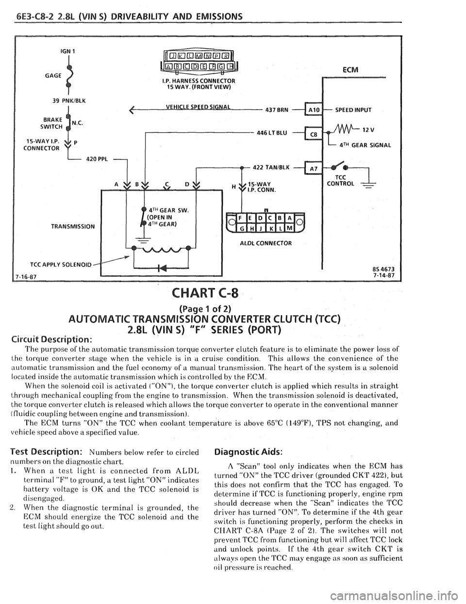
VEHICLE SPEED SIGNAL
SPEED INPUT
CONNECTOR
aTH GEAR SIGNAL
422 TAN/BLK
4TH GEAR SW.
TRANSMISSION
ALDL CONNECTOR
TCC APPLY SOLENOID
CHART C-8
(Page 1 of 2)
AUWBMATIC TRANSMISSION CONVERTER CLUTCH (TCC)
2.8L (VIN S) "F" SERIES (PORT)
Circuit Description:
The purpose of the automatic transmission torque converter clutch feature is to eliminate the power loss of
the torque converter stage when the vehicle is in a cruise condition. This allows the convenience of the
automatic transmission and the fuel economy of a manual transmission. The heart of the system is
a solenoid
located inside the automatic transmission which is controlled by the
ECM.
When the solenoid coil is activated ("ON"), the torque converter clutch is applied which results in straight
through mechanical coupling from the engine to transmission. When the transmission solenoid is deactivated,
the torque converter clutch is released which allows the torque converter to operate in the conventional manner
(fluidic coupling between engine and transmission).
The ECM turns
"ON" the 'KC when coolant temperature is above 65°C (14g°F), TPS not changing, and
vehicle speed above a specified value.
Test Description: Numbers below refer to circled Diagnostic Aids:
numbers on the diagnostic chart. A "Scan" tool only indicates when the ECM has 1. When a test light is connected from ALDL turned the TCC driver (grounded CKT 422), but terminal "F" to ground, a test light "ON" indicates
this does not confirm that the TCC has engaged. To battery voltage is OK and the TCC solenoid is
determine if TCC is functioning properly, engine rpm
disengaged.
should decrease when the "ScanJ' indicates the TCC
2. When the diagnostic terminal is grounded, the
driver has turned "ON". To determine if the 4th gear ECM energize the TCC "Ienoid and the switch is functioning properly, perform the checks in
test light should go out.
CIIART C-8A (Page 2 of 2). The switches will not
prevent TCC fi-om functioning but will affect TCC lock
and unlock points. If the 4th gear switch CKT is
always open the
TCC may engage as soon as sufficient
oil
pl.essure is reached.
Page 797 of 1825
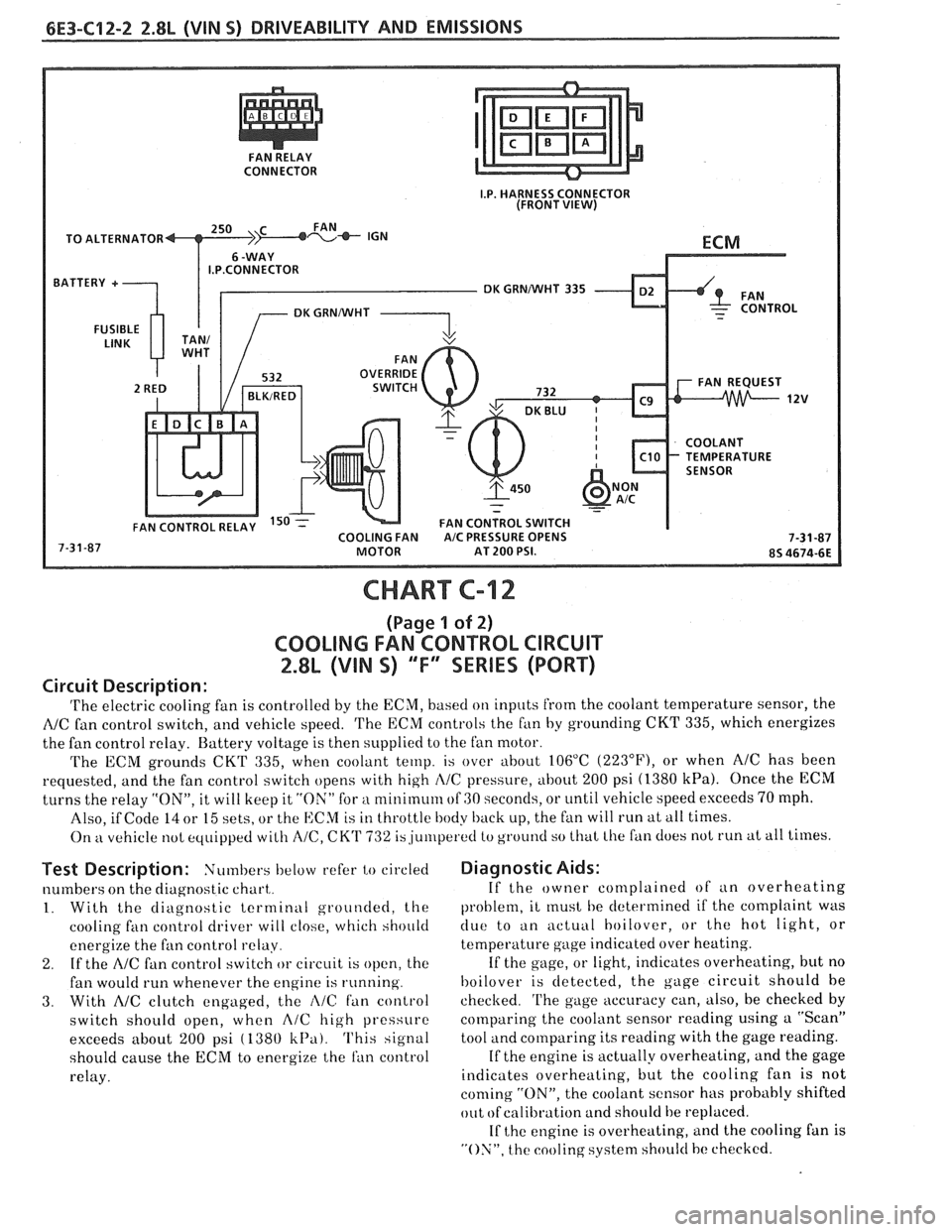
CONNECTOR
TO ALTERNATOR
I.P.CONNECTOR
DK GRNNVHT 335
CHART C-12
(Page 1 of 2)
COOLING FAN CONTROL CIRCUIT
2.8L (VIN S) "F" SERIES (PORT)
Circuit Description:
'I'he electric cooling fan is controlled by the ECM, based on inputs from the coolant temperature sensor, the
NC fan control switch, and vehicle speed. 'I'he ECM controls the f~in by grounding CKT 335, which energizes
the fan control relay. Battery voltage is then supplied to the fan motor.
The ECM grounds
CKT 335, when coolant temp. is over about 106°C (223"F), or when AIC has been
requested, and the fan control switch opens with high
I\/C pressure, about 200 psi (1380 kPa). Once the ECM
turns the relay "ON", it will keep it "ON" for a nlinirnum of GO seconds, or until vehicle speed exceeds 70 mph.
Also, if Code
14 or 15 sets, or the ECM is in throttle body back up, the fan will run at all times.
On
kt vehicle not equipped with A/C, CK'I' 732 is,ju~rlperetl to ground so that Lhe fan does not run at all times.
Test Description: Numbers below refer to circled
numbers on the diagnostic chart,.
1. With the diagnostic terminal grounded, the
cooling
fan control driver will close, which should
energize the fan control
relay.
2. If the A/C fan control switch or circuit is open, the
fan would run whenever the engine is running.
3. With AIC clutch engaged, the i\lC fan control
switch should open, when
A/C high pressure
exceeds about
200 psi ( 1380 k13a). This signal
should cause the
ECM to energize the ran control
relay.
Diagnostic Aids:
If the owner complained of an overheating
problem, it
rnust he determined if the complaint was
clue to an actuill hoilover, or the hot light, or
temperature gage indicated over heating.
If the gage, or light, indicates overheating, but no
hoilover is detected, the gage circuit should he
checked.
'I'he gage accuracy can, also, be checked by
comparing the coolant sensor reading using a "Scan"
tool and comparing its reading with the gage reading.
If the engine is actually overheating, and the gage
indicates overheating, but the cooling fan is not
coming "ON", the coolant sensor has probably shifted
out
ofcalibration and should be replaced.
If
the engine is overheating, and the cooling fan is
"ON", the cooling system should hc checked.
Page 802 of 1825
DRIVEABILITY AND EMISSIONS 2.8L (VIN S) 6E3-C13-1
SECTION C13
POSITIVE CRANKCASE VENTILATION (PC\/)
.... GENERAL DESCRIPTION ................ C13-1 FUNCTIONAL CHECK OF PCV VALVE C13-1
RESULTS OF INCORRECT OPERATION .... C13-1 ON-CAR SERVICE ..................... C13-2
DIAGNOSIS
......................... C13-1 PARTS INFORMATION ................. C13-2
GENERAL DESCRIPTION 4. Turn "OFF" the engine and remove PCV valve.
Shake valve and listen for the rattle of check
A "closed" crankcase ventilation (PCV) system is needle inside
the valve. If valve does not rattle,
used to provide more complete scavenging of replace
v4 ~1 1 ve.
crankcase vapors. Fresh air from the air cleaner is With this
system, any blow-by in excess of the
slipplied to the crankcase, mixed with blow-by gases system capacity (from a badly-worn engine, sustained
and then passed through a positive crankcase heavy load, etc.) is exhausted into the air cleaner and
ventilation
(PCV) valve into the intake manifold isdrawn into theengine.
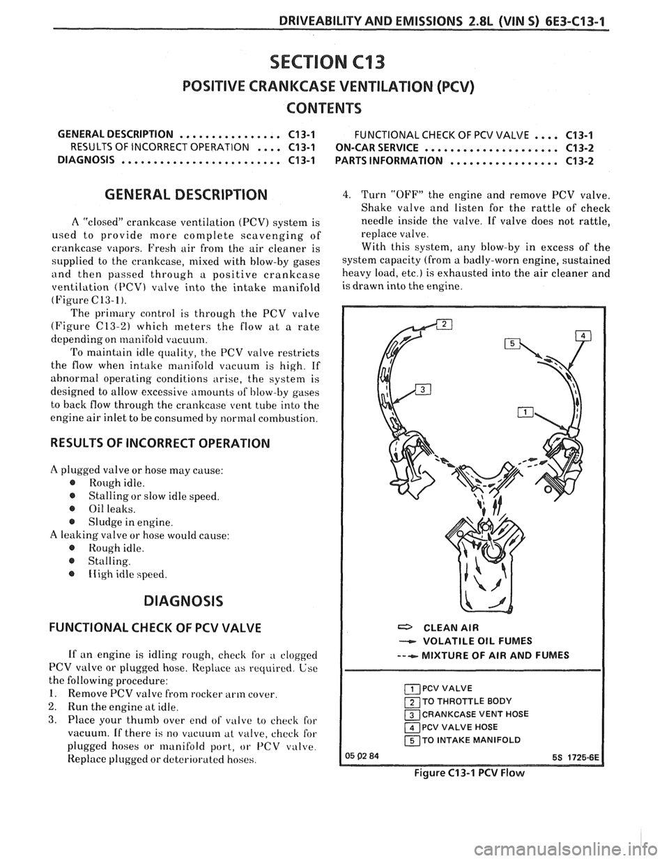
(Figure C13-1).
The primary control is through the PCV valve
(Figure
(213-2) which meters the flow at a rate
depending on manifold vacuum.
To maintain idle quality, the PCV valve restricts
the flow when intake manifold vacuum is high. If
abnormal operating conditions arise, the system is
designed to allow excessive amounts
of I,low-by gases
to back flow through the crankcase vent tube into the
engine air inlet to be consumed by normal combustion.
RESULTS OF INCORRECT OPERATION
A plugged valve or hose may cause:
@ Rough idle.
@ Stalling or slow idle speed.
@ Oil leaks.
@ Sludge in engine.
A leaking valve or hose would cause:
@ Rough idle.
@ Stalling.
@ Iiigh idle speed.
DIAGNOSIS
FUNCTIONAL CHECK OF PCV VALVE
If an engine is idling rough, check for a clogged
PCV valve or plugged hose. Replace as required. Use
the following procedure:
1. Remove PCV valve from rocker arm cover.
2. Run the engine at idle.
3. Place your thumb over end of vi~lcce to check for
vacuum. If there is
no vacuum at valve, chcck for
plugged hoses or
lrlanifold port, or 1'CV valve.
Replace plugged or dcterioratcd hoses.
a CLEAN AIR
VOLATILE OIL FUMES
---e- MIXTURE OF AIR AND FUMES
PCV VALVE
1 TO THROTTLE BODY
CRANKCASE VENT HOSE
1 PCV VALVE HOSE
150 INTAKE MANIFOLD
Figure C13-1 PCV Flow
Page 803 of 1825
6E3-C13-2 2.8L (VIN 5) DRIVEABILITY AND EMISSIONS
Proper operation of the PCV System is dependent ON-CAR SERVICE
upon a sealed engine. If oil sludging or dilution is
noted, and the PCV System is functioning properly,
An engine which is operated without any
check engine for possible cause and correct
to ensure crankcase ventilation can be damaged. Therefore, it is
that system will function as intended.
important to replace the PCV valve at
intervals
shown in Section
"OB".
Periodically, inspect the hoses and clamps and
replace any showing signs of deterioration.
I I PARTS INFORMATION
PART NAME GROUP
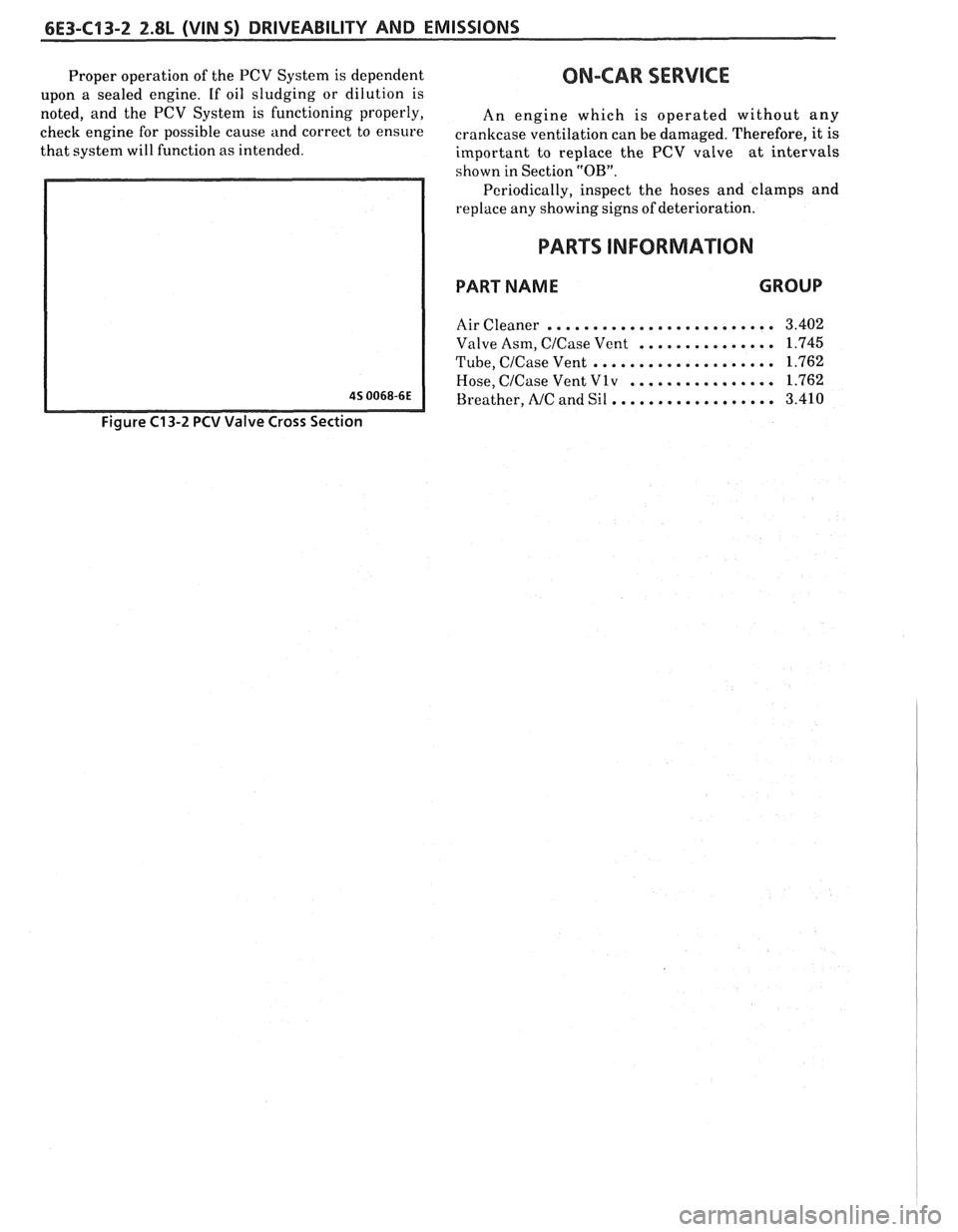
Figure C13-2 PCV Valve Cross Section
......................... Air Cleaner 3.402
............... Valve Asm, C/Case Vent 1.745
.................... Tube, C/Case Vent 1.762
................ Hose, C/Case Vent V 1 v 1.762
.................. Breather, NC and Sil 3.410
Page 804 of 1825
DRIVEABILITY AND EMISSIONS 5.OL (VIM F) & 5.7L(VIN 8) 6E3-A-1
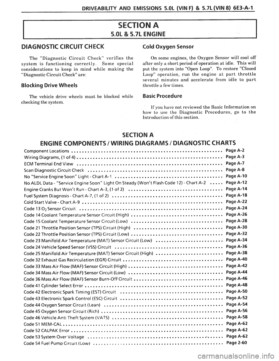
DIAGNOSIC CIRCUIT CHECK Cold Oxygen Sensor
The "Diagnostic Circuit Check" verifies the On some engines. the Oxygen Sensor will cool off
system is functioning correctly
. Some special after only a short period of operation at idle . This will
considerations to keep in mind while making the put the system into "Open Loop"
. To restore "Closed
"Diagnostic Circuit Check" are:
I. oop" operation. run the engine at part throttle
several minutes and accelerate from idle to part
Blocking Drive Wheels throttle a few times .
The vehicle drive wheels must be blocked while Basic Procedure
checking the system .
If you have not reviewed the Basic Information on
how to use the Diagnostic Procedures. go to the
Introduction of this section
.
SECTION A
ENGINE COMPONENTS
/WIRING DIAGRAMS 1 DIAGNOSTIC CHARTS
........................................................ Component Locations Page A-2
...................................................... Wiring Diagrams. (1 of 4) Page
A-3
ECMTerminal EndView ...................................................... PageA-7
.................................................. Scan Diagnostic Circuit Check Page
A-8
........................................ . No "Service Engine Soon" Light Chart A-I Page A-10
No ALDL Data
. "Service Engine Soon" Light On Steady (Won't Flash Code 12) . Chart A-2 ..... Page A-12
................................... . Engine Cranks But Won't Run Chart A.3, (1 of 2) Page A-14
......................................... Fuel System Diagnosis . Chart A.7, (1 of 2) Page
A-18
.................................................... . Cold Start Valve Chart A-9 Page A-22
..................................................... Code 13 O2 Sensor Circuit Page
A-24
.................................. Code 14 Coolant Temperature Sensor Circuit (High) Page
A-26
.................................. Code 15 Coolant Temperature Sensor Circuit (Low) Page
A-28
................................. Code 2 I Throttle Position Sensor (TPS) Circuit (High) Page
A-30
.................................. Code 22 Throttle Position Sensor (TPS) Circuit (Low) Page
A-32
......................... Code 23 Manifold Air Temperature (MAT) Sensor Circuit (Low) Page
A-34
........................................ Code 24 Vehicle Speed Sensor (VSS) Circuit Page
A-36
......................... Code 25 Manifold Air Temperature (MAT) Sensor Circuit (High) Page
A-38
..................................... Code 32 Exhaust Gas Recirculation (EGR) Circuit Page
A-40
................................... Code 33 Mass Air Flow (MAF) Sensor Circuit (High) Page
A-42
................................... Code 34 Mass Air Flow (MAF) Sensor Circuit (Low) Page
A-44
................................. Code 36 Mass Air Flow (MAF) Sensor Burn-Off Circuit Page
A-46
................................................... Code 41 Cylinder Select Error Page
A-48
...................................... Code 42 Electronic Spark Timing (EST) Circuit Page
A-50
...................................... Code 43 Electronic Spark Control (ESC) Circuit Page
A-52
............................................ Code 44 Oxygen Sensor Circuit (Lean) Page
A-54
............................................. Code 45 Oxygen Sensor Circu~t (Rich) Page
A-56
......................................... Code 46 Vehicle Anti Theft System (VATS) Page
A-58
Code51
MEM.CAL ........................................................... PageA-62
........................................................ Code52CALPAKError PageA-62
................................................... Code 53 System Over Voltage Page
A-62
................................................ Code 54 Fuel Pump Circu~t (Low) Page
2-60
Page 811 of 1825
6E3-A-8 5.OL (VIN F) & 5.7L(VIN 8) DRIVEABILITY AND EMISSIONS
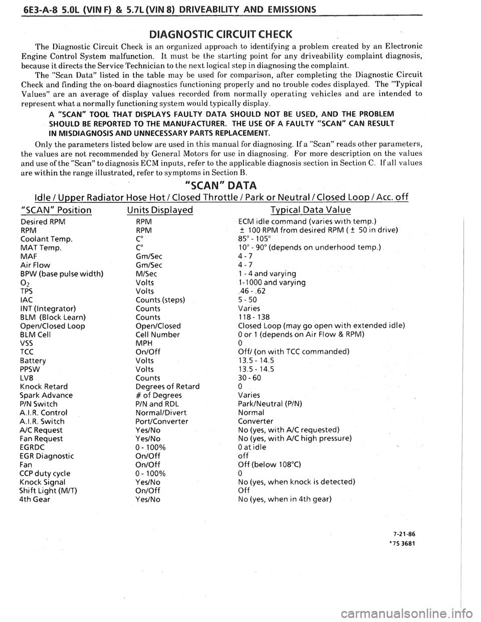
DIAGNOSIC CIRCUIXCHECK
The Diagnostic Circuit Checlc is an organized approach to identifying a problem created by an Electronic
Engine Control System malfunction. It
must be the starting point for any driveability complaint diagnosis,
because it directs the Service Technician to the next logical step in diagnosing the complaint.
The "Scan Data" listed in the table may be used for comparison, after completing the Diagnostic Circuit
Check and finding the on-board diagnostics functioning properly and no trouble codes displayed. The "Typical
Values" are an average of display values recorded from normally operating vehicles and are intended to
represent what a normally functioning system would typically display.
A "SCAN" TOOL THAT DISPLAYS FAULTY DATA SHOULD NOT BE USED, AND THE PROBLEM
SHOULD BE REPORTED TO THE MANUFACTURER. THE USE OF A FAULTY "SCAN" CAN RESULT
IN MISDIAGNOSIS AND UNNECESSARY PARTS REPLACEMENT.
Only the parameters listed below are used in this manual for diagnosing. If a "Scan" reads other parameters,
the values are not recommended by General Motors for use in diagnosing. For more description on the values
and use of the "Scan" to diagnosis ECM inputs, refer to the applicable diagnosis section in Section C.
If all values
are within the range illustrated, refer to symptoms in Section
B.
"SCAN" DATA
Idle / Upper Radiator Hose Hot / Closed Throttle / Park or Neutral /Closed Loop /Acc. off
"SCAN" Position Units Displayed Typical Data Value
Desired RPM RPM ECM ~dle command (vanes w~th temp.)
RPM RPM
+ 100 RPM from desired RPM ( k 50 ~n drive)
Coolant Temp.
CO 85" - 105"
MAT Temp. CO 10" - 90" (depends on underhood temp.)
MAF G
m/Sec 4-7
Air Flow
Gm/Sec 4 - 7
BPW (base pulse width)
M/Sec 1 - 4 and varying
02 Volts 1 - 1000 and varying
TPS Volts 46 - .62
I AC Counts (steps)
5 - 50
INT (Integrator) Counts
Vanes
BLM (Block Learn) Counts 118- 138
Open/Closed Loop Open/Closed Closed Loop (may go open with extended idle)
BLM Cell Cell Number
0 or 1 (depends on Air Flow & RPM)
VSS MPH 0
TCC
On/Off Off/ (on wlth TCC commanded)
Battery Volts 13.5
- 14.5
PPSW
Volts 13.5- 14.5
LV8 Counts 30
- 60
Knock Retard Degrees
of Retard 0
Spark Advance
# of Degrees Varies
PIN
Swltch PIN and RDL ParkINeutral (PIN)
A.I. R. Control
Normal/Divert Normal
A.I.R. Switch
PortIConverter Converter
NC Request Yes/No No (yes, wlth NC requested)
Fan Request
Yes/No No (yes, with NC high pressure)
EGRDC 0- 100%
0 at idle
EGR Diagnostic
On/Off off
Fan
OnIOff Off (below 108°C)
CCP duty cycle 0
- 100% 0
Knock Signal
YesINo No (yes, when knock is detected)
Shift Light
(MIT) On/Off Off
4th Gear
Yes/No No (yes, when in 4th gear)
Page 813 of 1825
TO MAF SENSOR
POWER & BURN-OFF
RELAY, OIL PRESS. SW.
.....-
439 PNKIBLK
419 BRNNVHT
SERIAL DATA
451 WHTIBLK
450
BLWHT
ALDL CONNECTOR
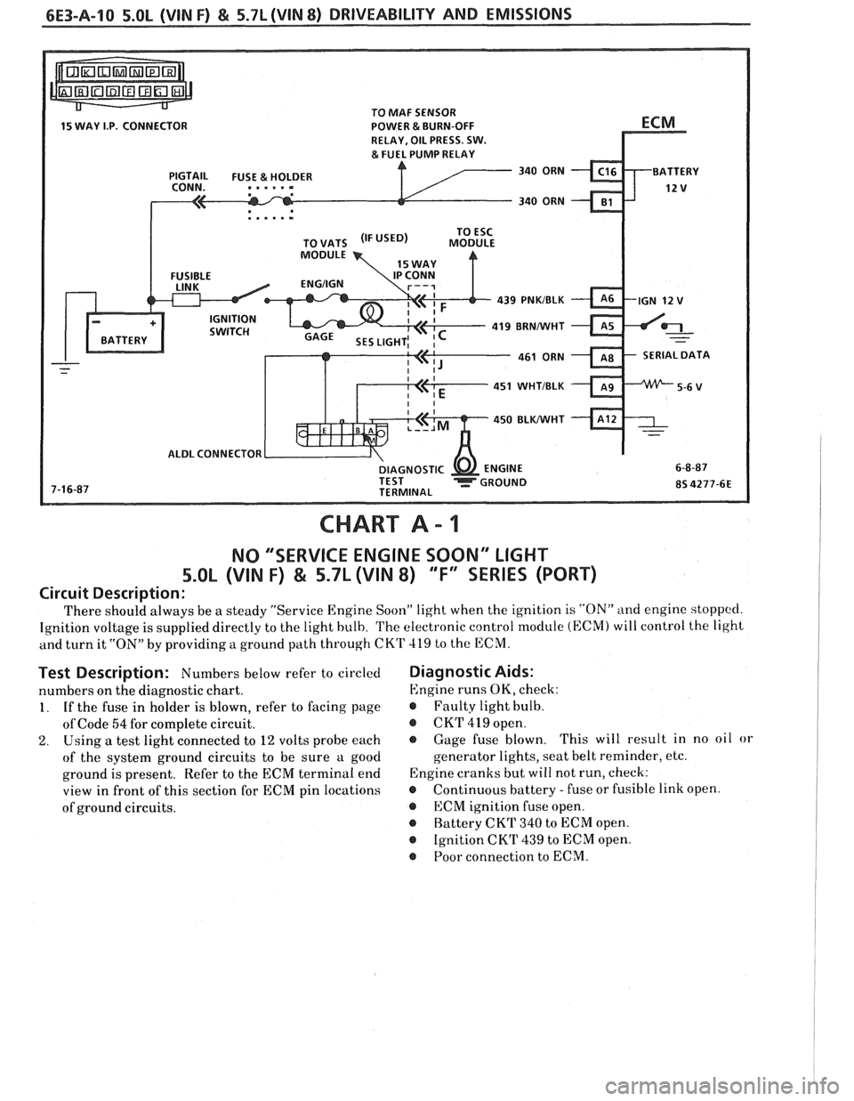
CHART A - 1
NO "'SERVICE ENGINE SOON" LIGHT
5.OL (VIN F) & 5.7L (VIN 8) "F'XSEBIE'S (PORT)
Circuit Description:
There should always be a steady "Service Engine Soon" light when the ignition is "ON" and engine stoppccl.
Ignition voltage is supplied directly to the light bulb. The electronic control module (ECM) will control the light
and turn it
"ON" by providing a ground path through CKT 419 to the ECM.
Test Description: Numbers below refer to circled
numbers on the diagnostic chart.
1. If the fuse in holder is blown, refer to facing page
of Code
54 for complete circuit.
2. Using a test light connected to 12 volts probe each
of the system ground circuits to be sure a good
ground is present. Refer to the ECM terminal end
view in front of this section for ECM pin locations
of ground circuits.
Diagnostic Aids:
Engine runs OK, check:
r Faulty light bulb.
@ CKrI' 419 open.
@ Gage fuse blown. This
will result in no oil or
generator lights, seat belt reminder, etc.
Engine cranks but will not run, check:
r Continuous battery - fuse or fusible link open.
@ ECM ignition fuse open.
r Battery CKT 340 to ECM open.
@ Ignition CKT 439 to ECM open.
@ Poor connection to ECM.
Page 815 of 1825
6E3-A-12 5.OL (VIN F) & 5.7L (VIN 8) DRIVEABILITY AND EMISSIONS
TO MAF SENSOR
POWER & BURN-OFF
, . . . . .
439 PNWBLK
419 BRNNVHT
SERIAL DATA
451
WHTIBLK
450 BLKIWHT
ALDL CONNECTOR
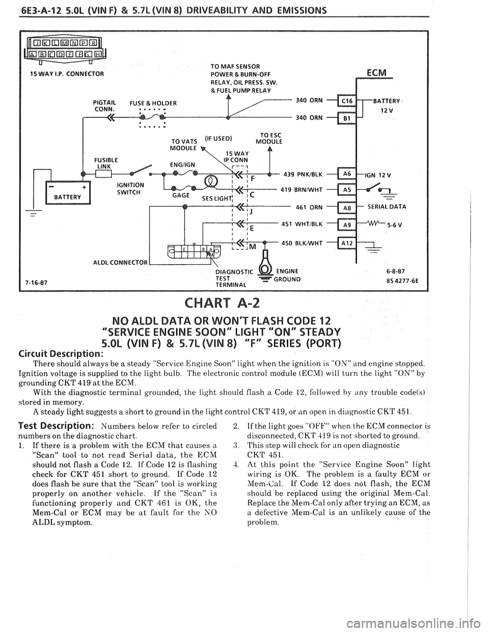
CHART A-2
NO ALDL DATA OR WON'T FLASH CODE 12
""SERVICE ENGINE SOON" LIGHT '"ON" STEADY
5.OL (VIN F) & 5.7L (VIN 8) ""FYEERIES (PORT)
Circuit Description:
'I'here should always be a steady "Service Engine Soon" light when the ignition is "ON" and engine stopped.
Ignition voltage is supplied to the light bulb.
'I'he electronic control module (ECM) will turn the light "ON" by
grounding CKT 419 at the ECM.
With the diagnostic terminal grounded, the light should flash
a Code 12, followed by any trouble code(s)
stored in memory.
A steady light suggests a short to ground in the light control CKT 419, or tin open in cliagnostic CKT 451.
Test Description: Numbers below refer to circled
numbers on the diagnostic chart.
1. If there is a problem with the ECM that causes
a
"Scan" tool to not read Serial data, the ECM
should not flash a Code 12. If Code 12 is flashing
check for CKT 451 short to ground. If Code 12
does flash be sure that the "Scan" tool is working
properly on another vehicle. If the "Scan" is
functioning properly and CKT 461 is OK, the
Mem-Cal or ECM may be at fault for the NO
ALDL symptom. 2.
If
the light goes
"OFF" when the ECM connector is
disconnected,
CK'r 419 is not shorted to ground.
3. This step will check for an open diagnostic
CKT 451.
-2. At this point the "Service Engine Soon" light
wiring is OK. The problem is a faulty ECM or
Mem-Cal. If Code 12 does not flash, the ECM
should be replaced using the original Mem-Cal.
Replace the Mem-Cal only after trying an ECM, as
a defective Mem-Cal is an unlikely cause of the
problem.