1988 PONTIAC FIERO check engine
[x] Cancel search: check enginePage 885 of 1825
6E3-C1-10 5.OL (VIN F) & 5.7L (VIN 8) DRIVEABILITY AND EMISSIONS
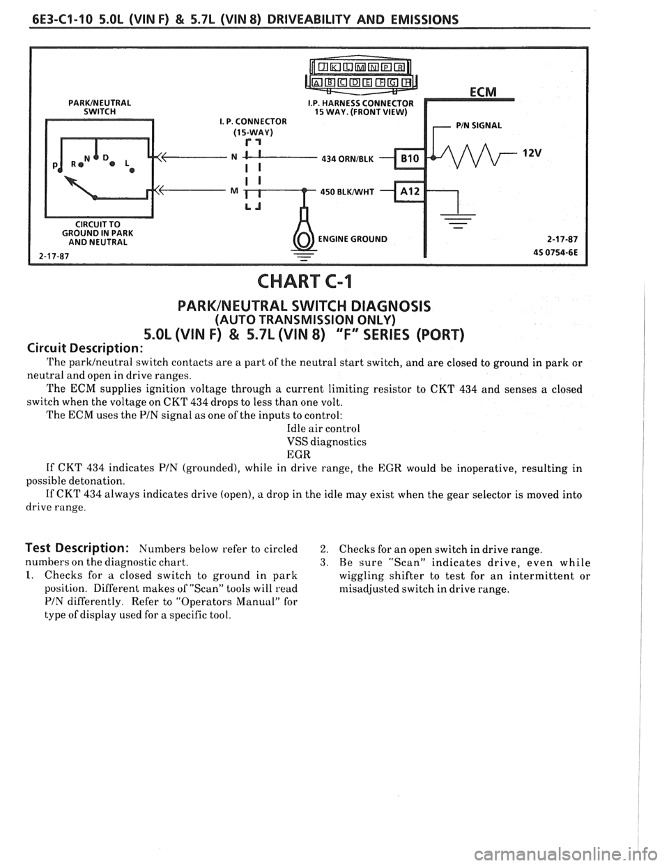
I.P. HARNESS CONNECTOR 15 WAY. (FRONT VIEW) I. P. CONNECTOR
N CL---- 434 ORNIBLK
450 BLWHT
ENGINE GROUND
CHART C-1
PARKINEUTRAL SWITCH DIAGNOSIS
(AUTO TRANSMISSION ONLY)
5.OL (VIN F) & 5.7L (VIN 8) "F" SERIES (PORT)
Circuit Description:
The parwneutral switch contacts are a part of the neutral start switch, and are closed to ground in park or
neutral and open in drive ranges.
The
ECM supplies ignition voltage through a current limiting resistor to CKT 434 and senses a closed
switch when the voltage on CKT
434 drops to less than one volt.
The ECM uses the PIN signal as one of the inputs to control:
Idle air control
VSS diagnostics
EGR
If CKT
434 indicates PIN (grounded), while in drive range, the EGR would be inoperative, resulting in
possible detonation.
If CKT 434 always indicates drive (open), a drop in the idle may exist when the gear selector is moved into
drive range.
Test Description: Numbers below refer to circled 2. Checks for an open switch in drive range.
numbers on the diagnostic chart.
3. Be sure "Scan" indicates drive, even while
1. Checks for a closed switch to ground in park
wiggling shifter to test for an intermittent or
position. Different makes of "Scan" tools will
read rllisadjusted switch in drive range.
PIN differently. Refer to "Operators Manual" for
type of display used for a specific tool.
Page 888 of 1825
DRIVEABILITY AND EMISSIONS 5.OL (VIN F) & 5.7L (VIN 8) 6E3-C2-1
SECTION C2
FUEL CONTROL SYSEENI
CONTENTS
GENERAL DESCRIPTION . . . . . . . . . . . . . . . . C2-1
PURPOSE ........................ C2-1
MODES OF OPERATION . . . . . . . . . . . . . . C2-2
Starting Mode . . . . . . . . . . . . . . . . . . . C2-2
Clear Flood Mode.. . . . . . . . . . . . . . . . C2-2
Run Mode.. . . . . . . . . . . . . . . . . . . . . . C2-2
Acceleration Mode.. . . . . . . . . . . . . . . C2-2
Deceleration Mode . . . . . . . . . . . . . . . C2-3
Battery Voltage Correction Mode . . . . . C2-3
Fuel Cutoff Mode . , . . . . . . . . . . . . . . . C2-3
FUEL CONTROL SYSTEM . . . . . . . . . . . . . . C2-3
Basic System Operation . . . . . . . . . . . . C2-3
Throttle Body Unit . . . . . . . . . . . . . . . . C2-3
Fuel Rail . . . . . . . . . . . . . . . . . . . . . . . C2-3
Fuel Injectors . . . . . . . . . . . . . . . . . . . . C2-3
Pressure Regulator . . . . . . . . . . . . . . . C2-4
IAC Valve . . . . . . . . . . . . . . . . . . . . . . . C2-4
Fuel Pump Electrical Circuit . . . . . . . . , C2-5
DIAGNOSIS
......................... C2-5
FUEL CONTROL SYSTEM . . . . . . . . . . . . . . C2-5
IDLE AIR CONTROL VALVE . . . .. 0.. . a. C2-5
FUEL SYSTEM PRESSURE TEST . .. . . . . . . C2-5
ON-CAR SERVICE
. . . . . . . . . . . . . . . . . . . . . C2-5
PORT FUEL INJECTION COMPONENTS . . . . C2-5
FUEL PRESSURE RELIEF PROCEDURE . . . . . C2-5
Plenum ........................ C2-5
FUEL RAlL ASSEMBLY . . . . . . . . . . . . . . . . C2-6
FUEL
RAlL SERVICE . . . . . . . . . . . . . . . . . . . C2-7
IDENTIFICATION . . . . . . . . . . . . . . . . . . . C2-7
UNlT SERVICE PROCEDURES .. . . . . . . . .. C2-7
COLD START TUBE & VALVE ASSEMBLY.. . C2-7
PARTS INFORMATION
. . . . . . . . . . . . . . . C2-9
FUEL PRESSURE CONNECTION ASSY. . . . . C2-10
FUEL INJECTORS (Rail Removed) . . . . . . . . C2-10
PRESSURE REGULATOR (Rail Removed) . . . C2-10
COLD START FUEL INJECTION SWITCH . . . C2-11
THROTTLEBODY ................... C2-11
THROTTLE BODY SERVICE IDENTIFICATION
. C2-12
UNlT REPAIR PROCEDURES . . . . . . . . . . . . C2-12
TPS Adjustment .............. C2-12
MINIMUM IDLE SPEED CHECK . . . . . . . . . . . C2-12
PARTSINFORMATION ................. C2-15
IDLE AIR C'NT' L VALVE ASSY & GASKET . . C2-15
CLEAN AIR COVER &GASKET . . . . . . . . . . C2-15
IDLE AIR CONTROUCOOLANT CVR. ASSY . C2-15
Throttle Body Removed From Engine . . C2-15
FUEL PUMP RELAY . . . . . . . . . . . . . .,. . . . C2-16
OIL PRESSURE SWITCH . . . . . . . . . . . . . . . C2-16
PARTS INFORMATION . . . . . . . . . . . . . . . . . C2-16
GENERAL DESCRIPTION
PURPOSE
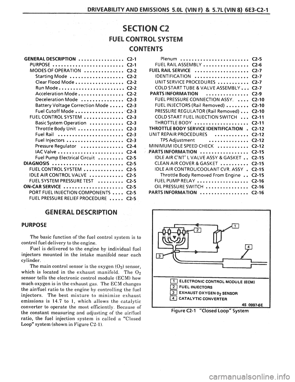
The basic function of the fuel control system is to
control fuel delivery to the engine.
Fuel is delivered to the engine by individual fuel
injectors mounted in the intake manifold near each
cylinder.
The main control sensor is the oxygen
(02) sensor,
which is located in the exhaust manifold. The
O2
sensor tells the electronic control module (ECM) how
much oxygen is in the exhaust gas.
The ECM changes
the
airlfuel ratio to the engine by controlling the fuel
injectors.
The best mixture to minimize exhaust
emissions is
14.7 to 1, which allows the catalytic
converter to operate the most efficiently. Because of
the constant measuring and adjusting of the
airlfuel
ratio, the fuel injection system is called a "Closed
Loop" system (shown in Figure
C2-I).
EXHAUST OXYGEN 02 SENSOR
CATALYTIC CONVERTER
Figure C2-1 "Closed Loop" System
Page 889 of 1825
6E3-C2-2 5.OL (VIN F) & 5.7L(VIN 8) DRIVEABILITY AND EMISSIONS
MODES OF OPERATION
The ECM looks at voltages from several sensors to
determine how much fuel to give the engine. The fuel
is delivered under one of several conditions, called
"modes". All the modes are controlled by the ECM
and are described below.
Starting Mode
When the ignition is first turned "ON", the ECM
will turn "ON" the fuel pump relay for two seconds,
and the fuel pump will build up pressure. The ECM
then checks the coolant temperature sensor, throttle
position sensor, and determines the proper airlfuel
ratio for starting. This ranges from 1.5
: 1 at -36°C
(-33°F) to 14.7:l at 94°C (201°F). The ECM controls
the amount of fuel delivered in the starting mode by
changing how long the injectors are pulsed "ON".
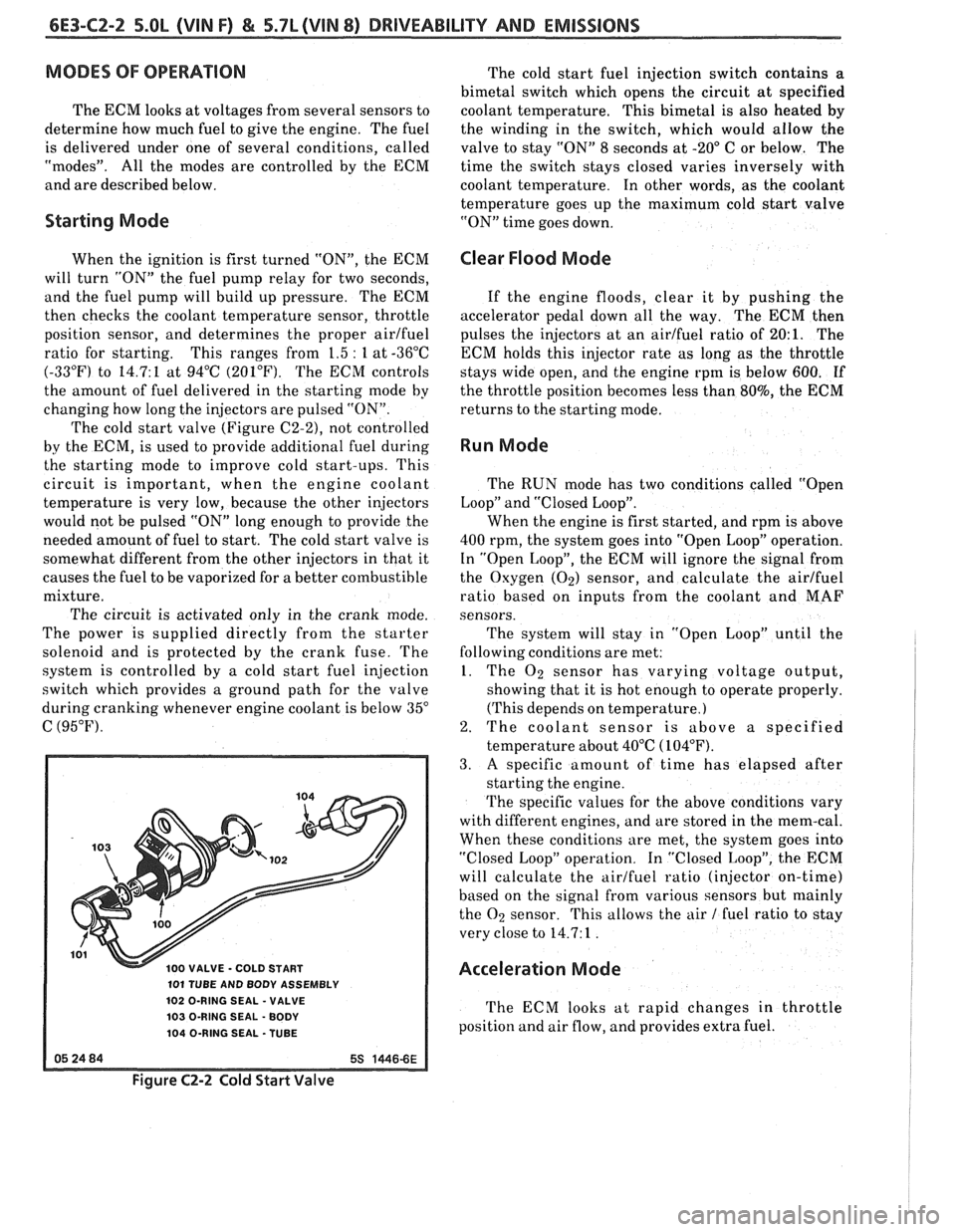
The cold start valve
(Figure C2-2), not controlled
by the ECM, is used to provide additional fuel during
the starting mode to improve cold start-ups. This
circuit is important, when the engine coolant
temperature is very low, because the other injectors
would not be pulsed "ON" long enough to provide the
needed amount of fuel to start. The cold start valve is
somewhat different from the other injectors in that it
causes the fuel to be vaporized for a better combustible
mixture.
The circuit is activated only in the crank mode.
The power is supplied directly from the starter
solenoid and is protected by the crank fuse. The
system is controlled by a cold start fuel injection
switch which provides a ground path for the valve
during cranking whenever engine coolant is below
35"
C (95°F).
100 VALVE - COLD START
101 TUBE AND BODY ASSEMBLY
102 O-RING SEAL
- VALVE
103 O-RING SEAL
- BODY
104 O-RING SEAL -TUBE
The cold start fuel injection switch contains a
bimetal switch which opens the circuit at specified
coolant temperature. This bimetal is also heated
by
the winding in the switch, which would allow the
valve to stay "ON" 8 seconds at
-20" C or below. The
time the switch stays closed varies inversely with
coolant temperature. In other words, as the coolant
temperature goes up the maximum cold start valve
"ON" time goes down.
Clear Flood Mode
If the engine floods, clear it by pushing the
accelerator pedal down all the way. The ECM then
pulses the injectors at an airlfuel ratio of
20:l. The
ECM holds this injector rate as long as the throttle
stays wide open, and the engine rpm is below 600.
If
the throttle position becomes less than 80%, the ECM
returns to the starting mode.
Run Mode
The RUN mode has two conditions called "Open
Loop" and "Closed Loop".
When the engine is first started, and rpm is above
400 rpm, the system goes into "Open Loop" operation.
In "Open Loop", the ECM will ignore the signal from
the Oxygen
(Oz) sensor, and calculate the airlfuel
ratio based on inputs from the coolant and MAF
sensors.
The system will stay in
"Open Loop" until the
following conditions are met:
1. The O2 sensor has varying voltage output,
showing that it is hot enough to operate properly.
(This depends on temperature.)
2. The coolant sensor is above a specified
temperature about 40°C
(104°F).
3. A specific amount of time has elapsed after
starting the engine.
The specific values for the above conditions vary
with different engines, and are stored in the mem-cal.
When these conditions are met, the system goes into
"Closed Loop" operation. In "Closed Loop", the ECM
will calculate the airlfuel ratio (injector on-time)
based on the signal from various sensors but
mainly
the O2 sensor. This allows the air 1 fuel ratio to stay
very close to 14.7: 1
.
Acceleration Mode
The ECM looks at rapid changes in throttle
position and air flow, and provides extra fuel.
Figure C2-2 Cold Start Valve
Page 892 of 1825
DRIVEABILITY AND EMISSIONS 5.OL (VIN F) & 5.7L (VIN 8) 6E3-C2-5
Fuel Pump Electrical Circuit
When the ignition is first turned "ON", without
the engine running, the ECM will turn the fuel pump
relay "ON" for two seconds.
This builds up the fuel
pressure quickly. If the engine is not started within
two seconds, the ECM will shut the fuel pump "OFF"
and wait until the engine is cranking. As soon as the
engine is cranked, the ECM will turn the relay "ON"
and run the fuel pump.
As
a backup system to the fuel pump relay, the
fuel pump can also be turned "ON" by the oil pressure
switch. The oil pressure switch is a normally open
switch which closes when oil pressure reaches about
28
kPa (4 psi). If the fuel pump relay fails, the oil
pressure switch will close, and run the fuel pump.
An inoperative fuel pump relay can result in long
cranking times, particularly if the engine is cold but
should result in
a Code 54.
An inoperative fuel pump would cause a no start
condition. A fuel pump which does not provide enough
pressure can result in poor performance.
DIAGNOSIS
FUEL CONTROL SYSTEM
Some failures of this system will result in an
"Engine Cranks But Won't Run". If
this condition
exists see CHART A-3. This chart will determine if
the problem is caused by the ignition system, ECM, or
fuel pump circuit. If
it's determined to be a fuel
problem CHART A-7 will be used. This includes the
injectors, pressure regulator, fuel pump, and fuel
pump relay. The fuel system wiring schematic is
covered on the facing page of Code CHART 54.
If a malfunction occurs in the fuel control system,
it usually results in either a rich or
a lean exhaust
condition. This condition is sensed by the oxygen
sensor and the ECM will change the fuel calculation
(injector pulse width) based on the
O2 sensor reading.
The change
made to the fuel calculation will be
indicated by a change in the block learn values, which
can be monitored by a "Scan" tool.
The normal block
learn values are around 128, and if the
O2 sensor is
sensing a lean condition, the EC
M will add fuel which
will result in a block learn value above 128.
If the O2
sensor is sensing a rich exhaust the ECM will reduce
fuel to the engine and this will result in block learn
values below 128. Some variations in block
learn
values are normal because all engines are not exactly
the same. However, if the block learn values are
+ 10
counts from 128 a system problem exists. If the block
learn values are greater than 138 see Code 44, for
items which can cause a lean system.
If the block learn values are less than 118 see Code
45 for items which can cause the system to run rich. If
a driveability symptom exists, refer to the
particular symptom in Section
"B" for additional
items to check.
IDLE AIR CONTROL VALVE
AUScan" tool will read IAC position in steps (counts).
"0" steps indicates the ECM is commanding the IAC to
be driven all the way in, to a fully seated position, and
this is usually caused by a vacuum leak. The higher
the number of counts the more air being allowed to
pass the IAC valve. CHART C-2C can be used to
diagnosis the IAC valve. Also refer to "Rough,
Unstable, or Incorrect Idle, Stalling" in symptoms,
Section "B" for other possibilities for the cause
of idle
problems.
FUEL SYSTEM PRESSURE TEST
A fuel system pressure test is part of several of the
diagnostic charts and symptom checks. To perform
this test, use the procedure in CHART A-7.
ON-CAR SERVICE
PORT FUEL INJECTION COMPONENTS
CAUTION:
Before servicing an injector, fuel
rail, or pressure regulator,
it is
necessary to relieve the pressure in
the fuel system, to minimize the
risk of fire and personal injury.
(See "Fuel Pressure Relief
Procedure" below). To reduce the
chance of personal injury, cover
the fuel line with
a shop cloth to
collect the fuel, and then place the
cloth in an approved container.
FUEL PRESSURE RELIEF PROCEDURE
1. Connect fuel gage J 34730-1 or equivalent to fuel
pressure valve. Wrap a shop towel around fitting
while connecting gage to avoid spillage.
2. Install bleed hose into an approved container and
open valve to bleed system pressure.
Plenum
(Figure
C2-6)
Remove or Disconnect
1. Negative battery cable.
2. Throttle, 'F.V., and cruise control cable.
3. Cable retaining bracket.
4.
'I'hrottle body retaining bolts (4).
5. 'L'l'S and IAC valve electrical connectors.
6. Vacuum hoses.
Page 899 of 1825
6E3-C2-12 5.OL (VIN F) & 5.7L (VIN 8) DRIVEABILITY AND EMISSIONS
UNIT REPAIR PROCEDURES
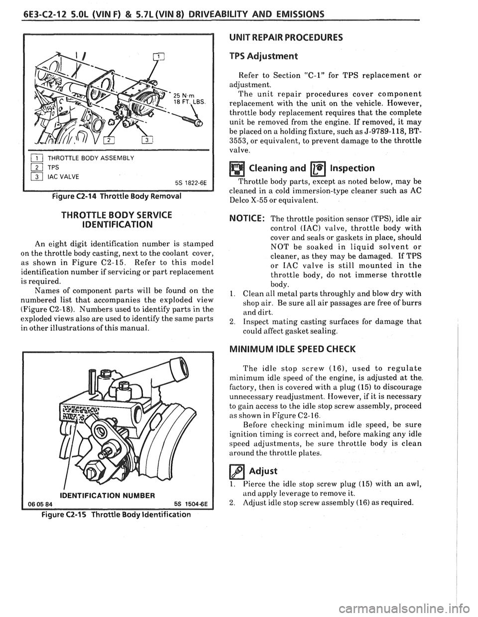
Figure C2-14 Throttle Body Removal
THROTTLE BODY SERVICE
IDENTIFICATION
An eight digit identification number is stamped
on the throttle body casting, next to the coolant cover,
as shown in Figure C2-15. Refer to this model
identification number if servicing or part replacement
is required.
Names of component parts will be found on the
numbered list that accompanies the exploded view
(Figure
C2-18). Numbers used to identify parts in the
exploded views also are used to identify the same parts
in other illustrations of this manual.
IDENTIFICATION NUMBER
Figure C2-15 Throttle Body Identification
TPS Adjustment
Refer to Section "C-1" for TPS replacement or
adjustment. The unit repair procedures cover component
replacement with the unit on the vehicle. However,
throttle body replacement requires that the complete
unit be removed from the engine. If removed, it may
be placed on a holding fixture, such as
5-9789-118, BT-
3553, or equivalent, to prevent damage to the throttle
valve.
Cleaning and a Inspection
Throttle body parts, except as noted below, may be
cleaned in a cold-immersion-type cleaner such
a; AC
Delco X-55 or equivalent.
NOTICE: The throttle position sensor (TPS), idle air
control
(IAC) valve, throttle body with
cover and seals or gaskets in place, should
NOT be soaked in liquid solvent or
cleaner, as they may be damaged. If TPS
or IAC valve is still mounted in the
throttle body, do not immerse throttle
body.
I. Clean all metal parts throughly and blow dry with
shop air. Be sure all air passages are free of burrs
and dirt.
2. Inspect mating casting surfaces for damage that
could affect gasket sealing.
MINIMUM IDLE SPEED CHECK
The idle stop screw (161, used to regulate
minimum idle speed of the engine, is adjusted at the.
factory, then is covered with a plug (15) to discourage
unnecessary readjustment. However, if it is necessary
to gain access to the idle stop screw assembly, proceed
as shown in Figure C2-16.
Before checking minimum idle speed, be sure
ignition timing is correct and, before making any idle
speed adjustments, be sure throttle body is clean
around the throttle plates.
Adjust
1. Pierce
the idle stop screw plug (15) with an awl,
and apply leverage to remove it.
2. Adjust idle stop screw assembly
(16) as required.
Page 900 of 1825
DRIVEABILITY AND EMISSIONS 5.OL (VIN F) & 5.7b (VIN 8) 6E3-CZ-13
IDLE STOP SCREW
ASSEMBLY
IDLE STOP
SCREW PLUG
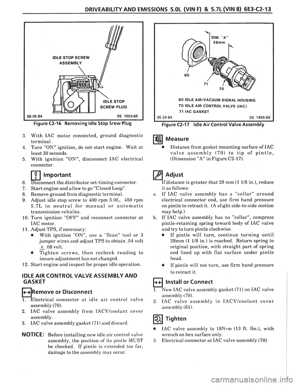
Figure C2-16 Removing Idle Stop Srew Plug
60 IDLE AIR/VACUUM SIGNAL HOUSING
70 IDLE AIR CONTROL VALVE (IAC)
71 IAC GASKET
Figure C2-17 Idle Air Control Valve Assembly
3. With IAC motor connected, ground diagnostic
terminal. Measure
4. Turn "ON" ignition, do not start engine. Wait at @ Distance from gasket mounting surface of IAC
least 30 seconds. valve assembly
(70) to tip of pintle,
5. With ignition
"ON", disconnect IAC electrical (Dimension
"A" in Figure C2-17).
connector.
Important
6. Disconnect
the distributor set-timing connector.
7. Start
engine and allow to go "Closed Loop".
8. Remove
ground from diagnostic terminal.
9. Adjust idle stop screw to 400 rpm 5.01,, 450 rpm
5.7L in neutral for manual or automatic
transmission vehicles.
10. Turn ignition "OFF" and reconnect connector at
IAC motor.
11. Adjust TPS, if necessary:
@ With ignition "ON", use a "Scan" tool or 3
jumper wires and adjust TPS to obtain .54 volt
+ .08 volt. - @ Tighten screws, then recheck reading to
insure adjustment has not changed.
12. Start engine and inspect for proper idle operation.
IDLE AIR CONTROL VALVE ASSEMBLY AND
CASKET
ORemove or Disconnect
1. Electrical connector at idle air control valve
assembly (70).
2. IAC valve assembly from IACVIcoolant cover
assembly.
3. IAC valve assembly gasket (71) and discard.
NOTICE: Before installing new idle air control valve
assembly, the position of its
pinlle MUST
be checked. If pintle is extended too far,
damage to the assembly
may occur
Adjust
If distance is greater that 28 mm (1 118 in.), reduce
it as follows:
a. If IAC valve assembly has a "collar" around
electrical connector end, use firm hand pressure
on pintle to retract it. (A slight side-to-side motion
may help.)
b. If
IAC valve assembly has no "collar", compress
pintle-retaining spring toward body of IAC valve
and try to turn pintle clockwise.
@ If pintle will turn, continue turning until
28mm
(1 118 in.) is reached. Return spring to
original position, with straight part of spring
end lined up with flat surface under pintle
head.
@ If pintle will not turn, use firm hand pressure
to retract it.
Install or Connect
1. New IAC valve assembly gasket (71) on IAC valve
assembly
(70).
2. IAC valve assembly in IACVIcoolant cover
assembly (61).
Tighten
IAC valve assembly to 18N.m (13 ft. Ibs.), with
wrench on hex surface only.
3. Electrical connector at IAC valve assembly (70).
Page 903 of 1825
6E3-CZ-16 5.OL (VIN F) & 5.7L(VIN 8) DRIVEABILITY AND EMISSIONS
Tighten
- @ Screw assemblies to 3.0 Nem (27.0 in. lbs.).
4. IAC valve assembly (70). (See "Idle Air Control
Valve and Gasket" instructions).
NOTICE: Before installing the IAC valve assembly,
the position of its pintle
MUST be checked.
If pintle is extended too far, damage to the
assembly may occur. (See
"Idle Air
Control Valve and Gasket" instructions.)
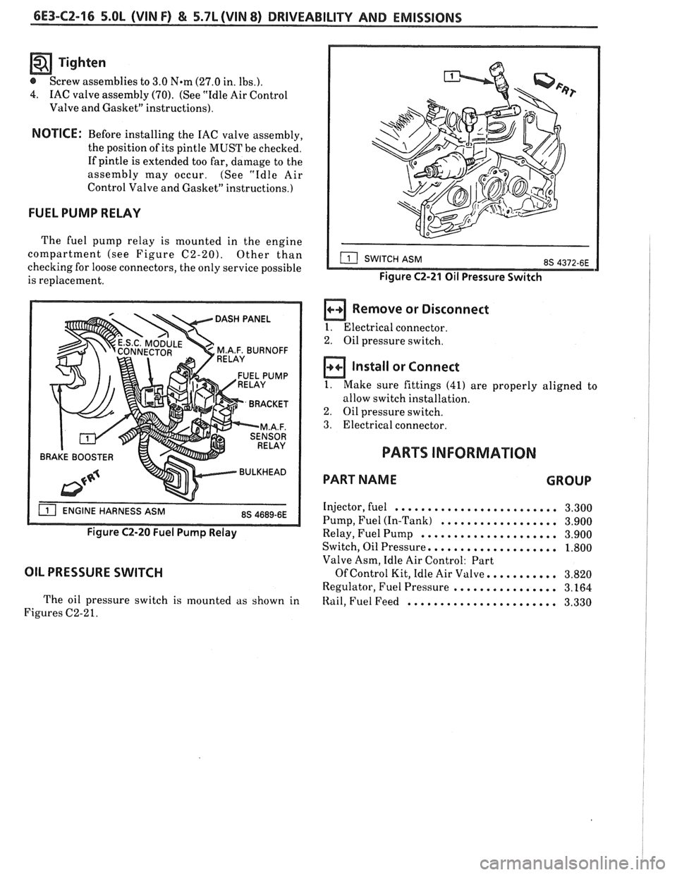
FUEL PUMP RELAY
The fuel pump relay is mounted in the engine
compartment (see Figure
C2-20). Other than
checking for loose connectors, the only service possible
is replacement.
BRAKE BOOSTER
Figure C2-20 Fuel Pump Relay
OIL PRESSURE SWITCH
The oil pressure switch is mounted as shown in
Figures C2-2
1.
Figure C2-21 Oil Pressure Switch
a Remove or Disconnect
I. Electrical connector.
2. Oil pressure switch.
Install or Connect
1. Make sure fittings (41) are properly aligned to
allow switch installation.
2. Oil pressure switch.
3. Electrical connector.
PARTS INFORMATION
PART NAME GROUP
Injector, fuel ......................... 3.300
Pump, Fuel (In-Tank)
.................. 3.900
Relay, Fuel Pump
..................... 3.900
Switch, Oil Pressure,
................... 1.800
Valve Asm, Idle Air Control: Part
Of Control Kit, Idle Air Valve. .......... 3.820
Regulator, Fuel Pressure
................ 3.164
Itail, Fuel Feed ....................... 3.330
Page 907 of 1825
6E3-C2-20 5.0L (VIN F) & 5.7L (WIN 8) DRIVEABILITY AND EMISSIONS
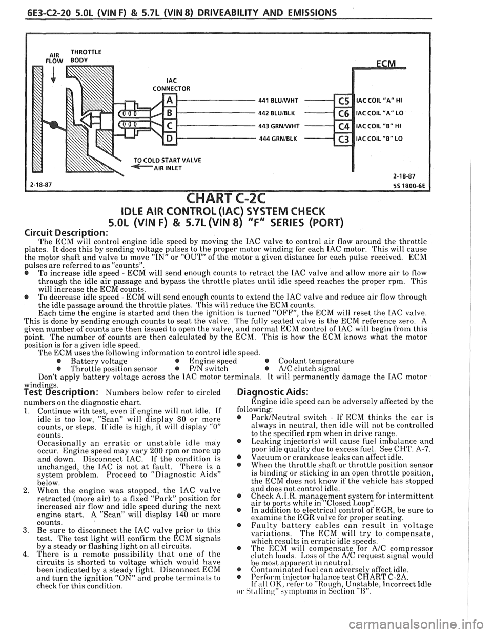
CONNECTOR - 441 BLUMlHT C5 IAC C0lL1'A" HI - 442 BLUIBLK C6 IAC COIL "A" LO - 443 GRNMlHT C4 IAC COIL "B" HI - 444 GRNIBLK C3 lAC COIL "B" LO v
START VALVE
CHART C-2C
IDLE AIR CONTROL (IAC) SYSTEM CHECK
S.OL (VIN F) & 5.7L (VIN 8) "F'" SERIES (PORT)
Circuit Description:
The ECM will control engine idle speed by moving the IAC valve to control air flow around the throttle
plates. It does this by sending voltage pulses to the proper motor winding for each IAC motor. This will cause
the motor shaft and valve to move
"IN" or "OUT" of the motor a given distance for each pulse received. ECM
pulses are referred to as "counts".
@ To increase idle speed - ECM will send enough counts to retract the IAC valve and allow more air to flow
through the idle air passage and bypass the throttle plates until idle speed reaches the proper rpm. This
will increase the ECM counts.
e To decrease idle speed - ECM will send enough counts to extend the IAC valve and reduce air flow through
the idle passage around the throttle plates. This will reduce the ECM counts.
Each time the engine is started and then the ignition is turned "OFF", the ECM will reset the IAC valve.
This is done by sending enough counts to seat the valve.
The fully seated valve is the ECM reference zero. A
given number of counts are then issued to open the valve, and normal ECM control of IAC will begin from this
point. The
number of counts are then calculated by the ECM. This is how the ECM knows what the motor
position is for a given idle speed.
The ECM uses the following information to control idle speed.
@ Battery voltage @ Engine speed @ Coolant temperature @ Throttle position sensor @ PIN switch e A/C clutch signal
Don't apply battery voltage across the IAC motor terminals. It will permanently damage the IAC motor
windin s. Test 6escription: Numbers below refer to circled
numbers on the diagnostic chart.
1. Continue with test, even if engine will not idle. If
idle is too low, "Scan" will display 80 or more
counts, or steps. If idle is high, it will display
"0"
counts.
Occasionally an erratic or unstable idle
[nay occur. Engine speed may vary 200 rpm or more up
and down. Disconnect IAC. If the condition is
unchanged, the IAC is not at fault.
There is a
system problem. Proceed to "Diagnostic Aids"
below.
2. When the engine was stopped, the IAC valve
retracted (more air) to
a fixed "Park" position for
increased air flow and idle speed during the next
engine start. A "Scan" will display 140 or more
coiints. 3. Be sure to disconnect the IAC valve prior to this
test.
The test light will confirm the ECM signals
by a steady or flashing light on all circuits.
4. There is a remote possibility that one of the
circuits is shorted to voltage which would have
been indicated by a steady light. Disconnect ECM
and turn the ignition "ON" and probe terminals to
check for this condition.
Diagnostic Aids:
Engine idle speed can be adversely affected by the
following:
@ ParMNeutral switch - If ECM thinks the car is
always in neutral, then idle will not be controlled
to the specified rpm when in drive range.
@ Leaking injector(s) will cause fuel imbalance and
poor idle quality due to excess fuel. See CHT.
A-7. @ Vacuum or crankcase leaks can affect idle. @ Whenthethrottleshaftorthrottlepositionsensor
is binding or sticking in an open throttle position,
the ECM does not know if the vehicle has stopped
and does not control idle.
@ Check A.I.R. management s stem for intermittent
air to orts while in "~losed~oo~". @ In ad&tion to electrical control of EGR, be sure to
examine the EGR valve for proper seating.
@ Faulty battery cables can result in voltage
variations. The ECM will try to compensate,
which results in erratic idle speeds.
@ 'I'he ECM will com ensate for A/C com ressor
clutch loacls. [.ass ofthe NC request sign8 would
he 11lost apparent, in neutral. @ Contalninatecl fuel can adverse1 affect idle. @ Perform i~!jector balance test C~ART C-2A. If ,111 OK, refer to "Rough, Unstable, Incorrect Idle or St ,tllinqW SJ tnptcfinsiin S~'ction "11''.