1988 PONTIAC FIERO instrument panel
[x] Cancel search: instrument panelPage 38 of 1825
CONTROL HANDLE INSTALLATION
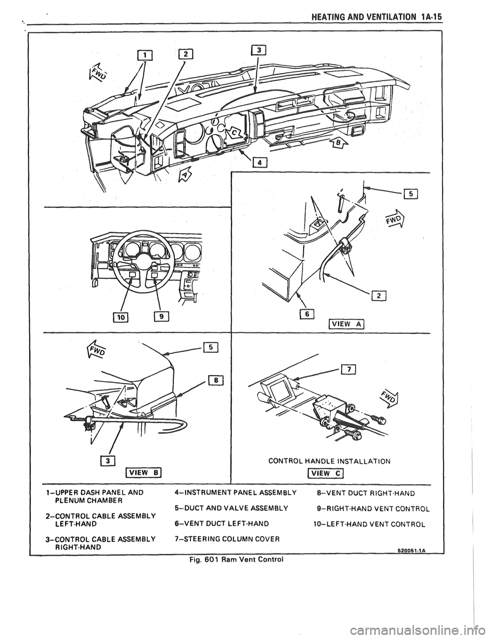
1-UPPER DASH PANEL AND 4-INSTRUMENT PANEL ASSEMBLY 8-VENT DUCT RIGHT-HAND
PLENUM CHAMBER
5-DUCT AND VALVE ASSEMBLY
9-RIGHT-HAND VENT CONTROL
2-CONTROL CABLE ASSEMBLY
LEFT-HAND
&VENT DUCT LEFT-HAND 10-LEFT-HAND VENT CONTROL
3-CONTROL CABLE ASSEMBLY 7-STEERING COLUMN
COVER
RIGHT-HAND
Page 39 of 1825
1A-16 HEATING AND VENTILATION
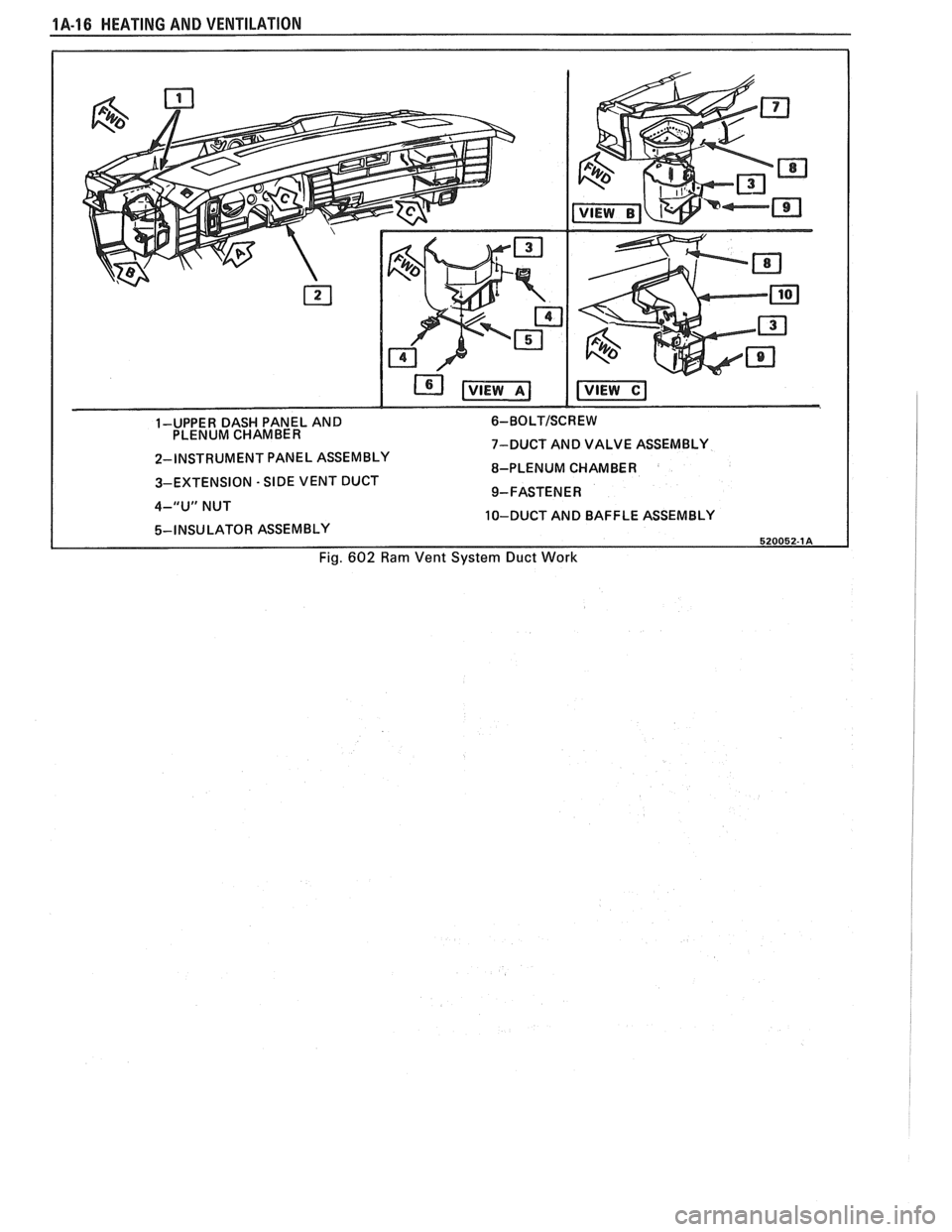
1-UPPER DASH PANEL AND 6- BO LT/SC R E W PLENUM CHAMBER
7-DUCT AND VALVE ASSEMBLY
2-INSTRUMENT PANEL ASSEMBLY
8-PLENUM CHAMBER
3-EXTENSION
- SIDE VENT DUCT
9-FASTENER
4-"U" NUT
10-DUCT AND BAFFLE ASSEMBLY
5-INSU LATOR ASSEMBLY 520052-1A
Fig. 602 Ram Vent System Duct Work
Page 63 of 1825
18-28 AIR CONDITIONING
DO NOT REPLACE the accumulator assembly
when:
1. Merely a dent is found in the outer shell of the
accumulator.
2. A
vehicle is involved in a collision and no phys-
ical perforation to the accumulator is found.
OM-VEHICLE SERVICE
R-"1 CHARGING CAPACITIES
The 420ml (14 fl. oz.) disposable can of R-12
refrigerant is equivalent to .399 kg (. 88 lb.).
BLOWER MOTOR
a Remove or Disconnect
1. Disconnect negative battery cable.
2. Remove motor cooling tube.
3. Disconnect electrical connections.
4. Remove blower motor attaching screws, remove
motor and case assembly.
5. Loosen retaining nut and remove blower cage
from motor shaft.
6. Inspect blower cage for broken vanes, etc.
Replace if necessary.
Install or Connect
1. Reverse removal procedure to reinstall. Replace
seals or sealant as required.
HI-BLOWER RELAY
Relay is a plug-in type with connector mounted
on top of the evaporator case.
BLOWER RESISTOR
Remove or Disconnect
1. Disconnect negative battery cable.
2. Disconnect electrical connections.
3. Remove two (2) screws, remove resistor.
Install or Connect
1. Reverse removal procedure to reinstall.
CONTROLLER, BLOWER SWITCH OR
WCUUM VALVE
Remove or Disconnect
1. Disconnect negative battery cable.
2. Remove NC control-radio console trim plate.
3. Remove three (3) NC control retaining screws.
4. Pull A/C control out and disconnect electrical
and vacuum connections and remove tempera-
ture cable.
5. Remove A/C control and replace vacuum valve
or blower switch as required.
Install or Connect
1. Reverse removal procedure to reinstall. Install
lower right screw in controller first to align con-
troller in console.
TEMPERATURE CONTROL CABLE,
VACUUM HARNESS
Remove or Disconnect
1. Remove the following hush panel(s):
a. Vacuum Harness - R.H. and L.H. hush
panel.
b. Temperature Cable
- R.H. hush panels.
Remove
controller/radio console trim plate.
Remove three (3) controller screws and pull
controller partially out of console.
Disconnect controller
end(s) of temperature
cable
andlor vacuum harness.
Disconnect component
end(s) of temperature
cable
andlor vacuum harness.
Install or Conned
1. Reverse removal procedure to reinstall. When
installing controller, install lower right screw
first to align controller location. Replace any
retaining straps, etc. removed.
2. Perform functional check of controller.
CONTROL WlRlNG HARNESS
a Remove or Disconnect
1. Disconnect negative battery cable.
2. Remove
control/radio console trim plate and
hush panels (see Section
8C).
3. Remove three (3) screws holding control in con-
sole and pull control out far enough to discon-
nect electrical and vacuum connector. Remove
controller.
4. Remove instrument panel carrier (see Section
8C).
5. Remove heater case covers (core and mode door
sides).
6. Remove two (2) interior screws and one (1)
exterior nut holding case to cowl. Pull left side
of case back to gain access to harness at cowl.
Case will still be retained by one (I) screw
behind the evaporator core
- do not attempt
complete removal of case. -
7. Loosen cowl grommet and disconnect purple
vacuum line.
Page 64 of 1825
AIR CONDITIONING 18-21
8. Disconnect blower motor
and blower resistor
electrical connection.
9. Remove hi-blower relay connector from evapo-
rator case.
10. Carefully pull
cowl grommet from cowl and pull
wiring
hmess into engine compartment.
Install or Connect
1. Reverse removal procedure to
reinstall. When
reinstalling controller, install lower right screw
first to align controller.
ACNENTILATIONIDEFROSVER DUCTS
See section 8C for removal.
HEATER CORE
Remove or Disconnect
1. Negative battery cable.
2. Drain cooling system.
3. Remove heater inlet and outlet hoses
from
heater core.
4. Remove right lower hush panel (see Section
8C).
5. Remove right
lower I.P. trim panel (see Section
8C) .
6. Remove lower right I.P. carrier to cowl screw.
7. Remove ECM attaching screws and move to the
side.
8. Remove four
(4) heater case cover screws.
Upper left screw may be reached with a long
318 ' socket extension through the I.P. openings
exposed by removal of the lower right I.P. trim
panel. Carefully lift the lower right corner of the
I.P. to align socket extension.
9. Remove heater case cover.
10. Remove core support plate
and baffle screws.
- -
11. Remove
heater core, support plate and baffle
from case.
Install or Conned
1. Reverse removal procedure to reinstall. Restore
all seals
and/or sealant disturbed during removal
procedure.
2. Refill cooling system and check for leaks.
LOWER (FLOOR) )-IEA"FEB$OU"fET
Remove or Disconnect
1. Console. (See Section 8C.)
2. L.H. and R.H. hush panels.
3. Two (2) floor outlet retaining screws.
4. Floor outlet from core case.
lnstall or Connect
1. Floor outlet to core case.
2. Two (2) floor outlet retaining screws.
3. L.H. and R.H. hush panels.
4. Console.
HEATER MODULE (CASE)
Remove or Disconnect
1. Disconnect negative battery cable.
2. Drain cooling system.
3. Remove hush panels and instrument panel car-
rier (see Section
8C).
4. Remove lower heater outlets.
5. Disconnect control cables and vacuum hoses at
module and controller.
6. Remove heater core.
7. Remove two (2) interior screws and one (I)
exterior nut holding case to cowl.
8. Remove evaporator core.
9. Remove screw holding case to cowl from engine
compartment side.
10. Remove case (module).
11. Transfer usable parts to new case (module).
lnstall or Conned
1. Reverse removal procedure to reinstall.
2. Refill coolant system.
3. Recharge
A/C system.
4. Inspect A/C and cooling system for leaks.
NC PRESSURE CYCLING SWITCH
Do not discharge A/C system. Pressure cycling
switch is mounted on
a Schrader-type valve.
Remove or Disconnect
1. Disconnect switch electrical connection.
2. Remove switch.
Install or Connect
1. Reverse removal procedure to reinstall. Tighten
switch to
4-5.5 N*m (35-49 in. lb.).
Ale CONTROL VACUUM TANK
Remove or Disconnect
1 . Disconnect vacuum hoses.
2. Remove vacuum
tank attaching screws, remove
tank.
lndall or Connect
1. Reverse removal procedure to
reinstall.
Page 113 of 1825
866 CHASSIS SHEET METAL
PROPER IDENTIFICATION AND CDAlrUmNG
OF INTERIOR PWSTIC TRlM
Interior plastic trim parts are normally supplied
in only one color. It is necessary to paint most parts.
Most vinyl headlinings and soft vinyl seat cushion and
hack cover assemblies are furnished in colors.
Instructions on how to identify each paintable
plastic part, and how to apply the available paint
materials are as follows:
Paintable plastic trim components, as used on
General Motors interiors, can be divided into three
general types:
@ Polypropylene Plastic
@ ABS Plastic
@ Vinyl Plastic
Excluding the soft vinyl seat cushion and seat
back trim cover assemblies, the plastic used most
widely on the interior of bodies is "POLYPROPYL-
ENE" and, as noted later, requires special refinishing
materials and procedures. Therefore, it is important
for a painter to be able to identify each plastic in order
to paint it satisfactorily. The purpose of the following
tests is to determine the identity of a given plastic so
that the proper paint procedure and refinishing mate-
rials will be used.
TEST PROCEDURE
Polypropylene, ABS or Vinyl Plastic
From a hidden backside portion of the part,
remove a sliver of plastic with a sharp blade.
Holding the sliver with needle-nose pliers, put it
to a flame and observe whether or not any
smoke is given off when burning.
ABS PLASTIC will give off a HEAVY BLACK
SMOKE, and POLYPROPYLENE will burn
clean.
However, if a sliver gives off OTHER THAN
HEAVY BLACK SMOKE, it is either DIRTY
POLYPROPYLENE OR IS VINYL. To deter-
mine which it is, the following burn test should
be made with the hot tip of a clean copper wire.
Heat the tip of the copper wire to a "red-glow"
with a propane (gas) torch.
Touch the heated wire to a hidden portion of the
plastic in question, to get some of the plastic on
the wire.
Return the wire, with its
now plastic-coated tip,
to the flame and observe for flame color.
If the flame given off from the wire is of the
GREEN-TURQUOISE-BLUE RANGE, then
the PLASTIC IS VINYL. (Any other color
flame would indicate the material is dirty poly-
propylene.
)
PAINWING lNTERiOR PWSTIC PARTS
Before painting, always check the body number
plate of the car for the
correct trim code color number
for that model year. The body number plate is located
on the upper horizontal surface of the shroud. Interior
color is color keyed to this "Trim Combination Num-
ber" (TR) on the body plate. Each paint supplier pro-
vides an interior color chart which identifies their
stock number, color name, gloss factor and trim com-
bination number for each "conventional" interior
color. Charts listing "vinyl" interior colors are also
provided.
"CONVENTIONAL" interior acrylic colors are
designed for use only on hard trim parts, such as:
1. Steel parts (primer or sealer required on new
service parts).
2. Hard POLYPROPYLENE plastic ("Special
Primer" required
- See GM Parts Catalog).
3. Hard ABS plastic (NO primer necessary).
"VINYL" interior colors are designed for soft
and/or flexible trim parts, such as instrument panel
cover pad assemblies, upper door trim pad assem-
blies, molded headlining panels, head rests and assist
handles. These colors require a final top coat of clear
vinyl spray, with instrument panel pads requiring a
"nonglare" clear final top coat. Other trim parts
require a degree of gloss to match similar adjacent
parts.
POLYPROPYLENE PUSTIC PARTS
The system for painting polypropylene parts
involves the use of a special primer. It is essential that
the service part be first primed with a coating of spe-
cial POLYPROPYLENE PRIMER (Detroit
Autobody
#PP-2250, or equivalent) according to factory recom-
mendations on the can. Because the primer acts as a
bonding agent between the plastic and acrylic lacquer, failure to use it will result in color coat "lifting"
and/or
"peeling" problems. After priming, the part can be
color coated with conventional interior acrylic
lacquer,
PROCEDURE
1. Wash part thoroughly with a cleaning solvent ("Acryli-Clean," "Prep-Sol," or equivalent) that
will not leave any greasy film.
2. Apply a thin, wet coat of the special polypropyl-
ene primer according to label directions on can.
Wetness of primer is best determined by observ-
ing gloss reflection of spray application in ade-
quate lighting. Be sure primer application
includes all edges. Allow
the primer to flash dry
ONE (1) MINUTE MINIMUM and TEN (10)
MINUTES MAXIMUM. (If the flash period
before color coating should extend beyond ten
minutes, the primer MUST be reapplied to
avoid previously mentioned adhesion
problems
.)
Page 114 of 1825
CHASSIS SHEET METAL 2@-7
3. During the above flash time period (1 to 10 min-
utes), apply appropriate "conventional" interior acrylic lacquer color as required and allow
painted part to dry for
4 to 5 hours before install-
ing on car.
RlGlD OW HARD ABS PMS"TIC PARTS
Rigid or hard ABS plastic requires no primer.
"Conventional" interior acrylic lacquers adhere satis-
factorily to hard ABS plastics.
Procedure
1. Wash part thoroughly with a cleaning solvent
(Acrylic-Clean, Pre-Kleano, Prep-Sol or equiv-
alent) to remove any dirt or grease.
2. Apply appropriate "conventional" interior
acrylic lacquer color. Apply only sufficient
color for proper hiding to avoid washout of
"grain" effect.
3. Allow to dry and then install part.
VINYL AND FLEXIBLE (Son) ABS
PLASTIC PARTS
The outer cover or skin material of "flexible"
instrument panel cover (pad) assemblies is made of an
ABSIPVC plastic blend. The same is true of many
"padded" door trim assemblies. The soft cushion pad-
ding under the I.P. skin is urethane foam plastic. The
most widely used
"flexible" vinyls (poly vinyl chlo-
ride)
are coated fabrics, such as used in seat trim,
some door trim assemblies, molded headlining panels
and sun visors. Most head rests are "flexible" vinyls.
Examples of "hard vinyls are: door and front seat
back assist handles and coat hooks.
The paint system of vinyl and flexible ABS
plastic involves the use of interior "vinyl" color and a
clear vinyl top coat.
Procedure
1. Wash part thoroughly with a vinyl cleaning and
preparation solvent ("Vinyl Press"
- Ditzler,
"Vinyl Prep Conditioner"
- Detroit Autobody
or equivalent) to remove greasy film or silicone.
Wipe off cleaner while still wet with clean,
lint-
free cloth.
2. Immediately after wiping face dry, apply inte-
rior "vinyl" color in wet coats allowing suffi-
cient flash time between coats (see label
directions on can). Use proper "vinyl" color as
designated by interior trim combinations. Apply
only sufficient color for proper hiding to avoid
washout of "grain" effect. No primer or
primer-
sealer is required.
3. Before the final vinyl color coat has dried, apply
two coats of clear vinyl top coat spray (instru-
ment panels will require the "nonglare" clear top
coat). Do not allow the first spray coat to com-
pletely dry before spraying on the second. Use
top coat with appropriate gloss level to match adjacent similar components. This
clear coat is
necessary to control the gloss requirement and
prevent
'tracking" (rubbing-off) of the color
coat after drying.
4. Allow to dry according to label directions before
installing part.
ON-VEHICLE SERVICE
CONCEALED HEADLIGHTS
The concealed headlights used on this model are
electrically operated. When the headlights are turned
on, solid state circuitry activates the actuators. This
same circuitry senses when the actuators stop moving
and removes the ground to deactivate the actuators.
When the headlights are turned off, the actuators run
in opposite direction closing the headlight doors.
Should an electrical failure occur in the head-
light circuit, they may be raised manually by rotating
the knob on the actuator in a counterclockwise direc-
tion until the headlights are fully open. The headlights
may be lowered by rotating the knob on the actuator in
a clockwise direction until the headlights are fully
closed.
For electrical circuit information and diagnosis,
refer to Section
8A of this manual.
If it is desired to raise the headlights with the
lights off, either of the following procedures may be
used:
1. Turn the lights on. After the headlights are
open, disconnect the electrical connections at
the actuator connectors. Turn the lights off. The
headlights will now remain in the open position.
2. Turn the parking lights on. Depress the head-
light rocker switch lightly. The headlights may
then be raised "up" fully with the lights off.
Adjust
Because of the number of adjustments possible
and the number of attaching points of the concealed
headlight body assembly
(9), only those attachments
which control the adjustment desired should be loos-
ened. Make one
adjbstment at a time.
NOTICE: The headlight door does NOT have
slotted mounting holes and therefore is not
adjustable by itself. This insures proper clearance
between the headlight door and the hood and
fenders in both the raised and lowered positions.
The entire headlight body assembly must be
adjusted to achieve the desired appearance and
fit. Care should be exercised when adjusting the
headlight body assembly. Severe hammer blows could damage the die cast aluminum headlight
body assembly.
TO RAISE OR LOWER the headlight body
assembly, proceed as follows:
1. Open hood.
2. Raise headlights.
Page 153 of 1825
385-2 STEERING WHEELS AND COLUMNS
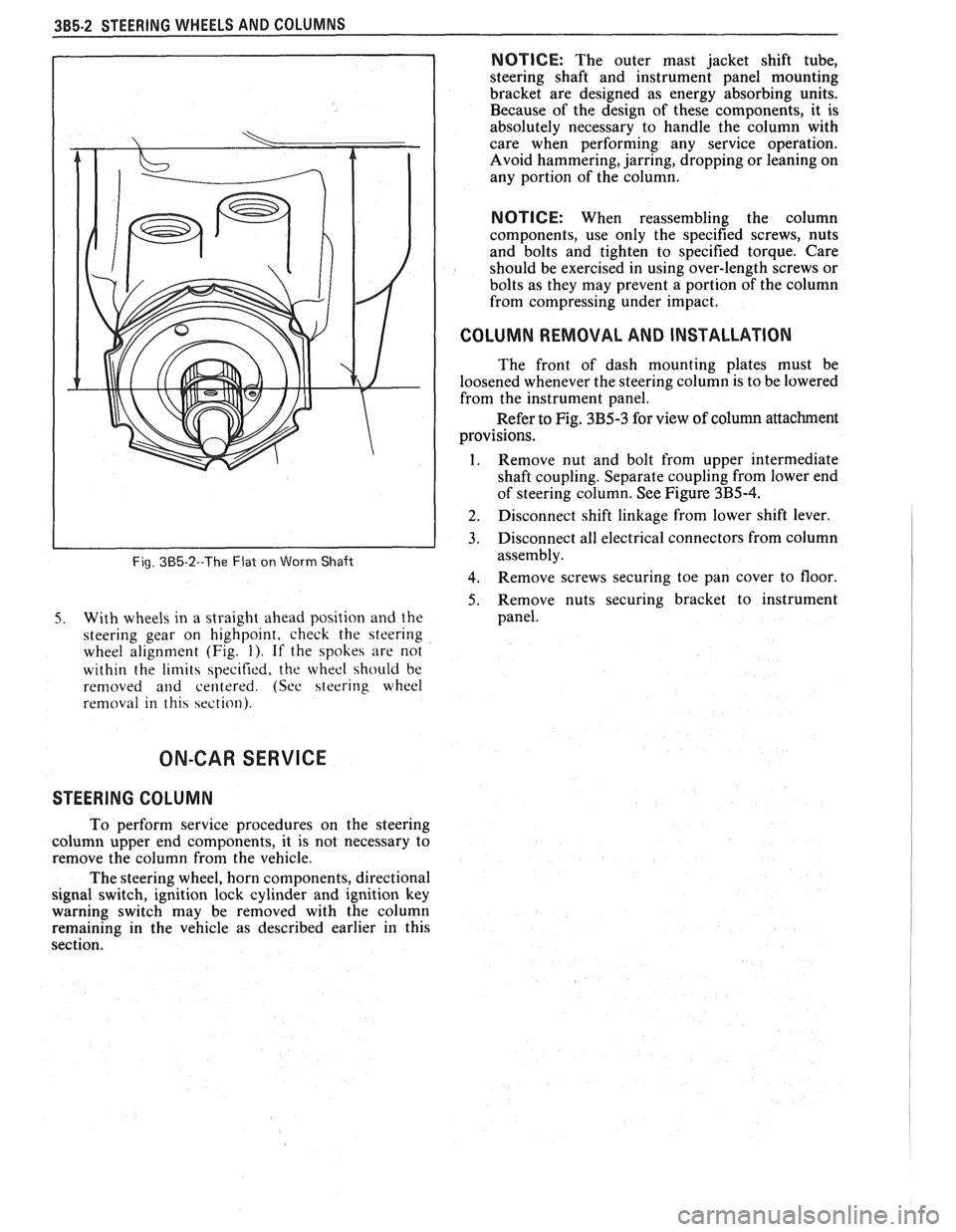
Fig. 385-2--The Flat on Worm Shaft
5. With wheels in a straight ahead position and the
steering gear on highpoint, check the steering
wheel alignment (Fig.
1). If the spokes are not
within the
limits specified, the wheel should be
removed
and centered. (See steering wheel
removal in this section).
NOTICE: The outer mast jacket shift tube,
steering shaft and instrument panel mounting
bracket are designed as energy absorbing units.
Because of the design of these components, it is
absolutely necessary to handle the column with
care when performing any service operation.
Avoid hammering, jarring, dropping or leaning on
any portion of the column.
NOTICE: When reassembling the column
components, use only the specified screws, nuts
and bolts and tighten to specified torque. Care
should be exercised in using over-length screws or
bolts as they may prevent a portion of the column
from compressing under impact.
I COLUMN REMOVAL AND INSTALLATION
The front of dash mounting plates must be
loosened whenever the steering column is to be lowered
from the instrument panel.
Refer to Fig. 3B5-3 for view of column attachment
provisions.
1. Remove nut and bolt from upper intermediate
shaft coupling. Separate coupling from lower end
of steering column. See Figure
3B5-4.
] 2. Disconnect shift linkage from lower shift lever.
3. Disconnect all electrical connectors from column
assembly.
4. Remove screws securing toe pan cover to floor
5. Remove nuts securing bracket to instrument
panel.
ON-CAR SERVICE
STEERING COLUMN
To perform service procedures on the steering
column upper end components, it is not necessary to
remove the column from the vehicle.
The steering wheel, horn components, directional
signal switch, ignition lock cylinder and ignition key
warning switch may be removed with the column
remaining in the vehicle as described earlier in this
section.
Page 295 of 1825
5-2 BRAKES
GENERAL DESCRIPTION
COMPOSIE EASTER CYLINDER
This vehicle uses a composite master cylinder which has
an aluminum body and a clear nylon reservoir with fluid
level indicators. The master cylinder uses a "quick take-up" feature in the
rear chamber to reduce pedal travel which may result from
increased fluid displacement required to move the caliper
piston. The quick take-up master cylinder includes a spring
loaded ball check valve which holds pressure in the
large-
diameter rear chamber. When the brake is first applied, the
movement of the rear piston causes fluid to be displaced
forward, past the primary piston primary seal and into the
primary high pressure chamber, which feeds the front
brakes. At a predetermined pressure, 480-690
kPa (70-100
mi), the ball unseats and fluid from the largi! rear bore is
disblaced past the ball and into the reservoir. The primary
and secondary high pressure chambers supply pressure to
the front and rear brakes, respectively, in the usual way.
When the pedal is released, the large-bore chamber is filled
with fluid by drawing fluid from the reservoir around the
quick take-up lip seal, and also through a small orifice in the
ball seat.
BRAKE FLUID LEVEL INDICATOR
(Figure 1)
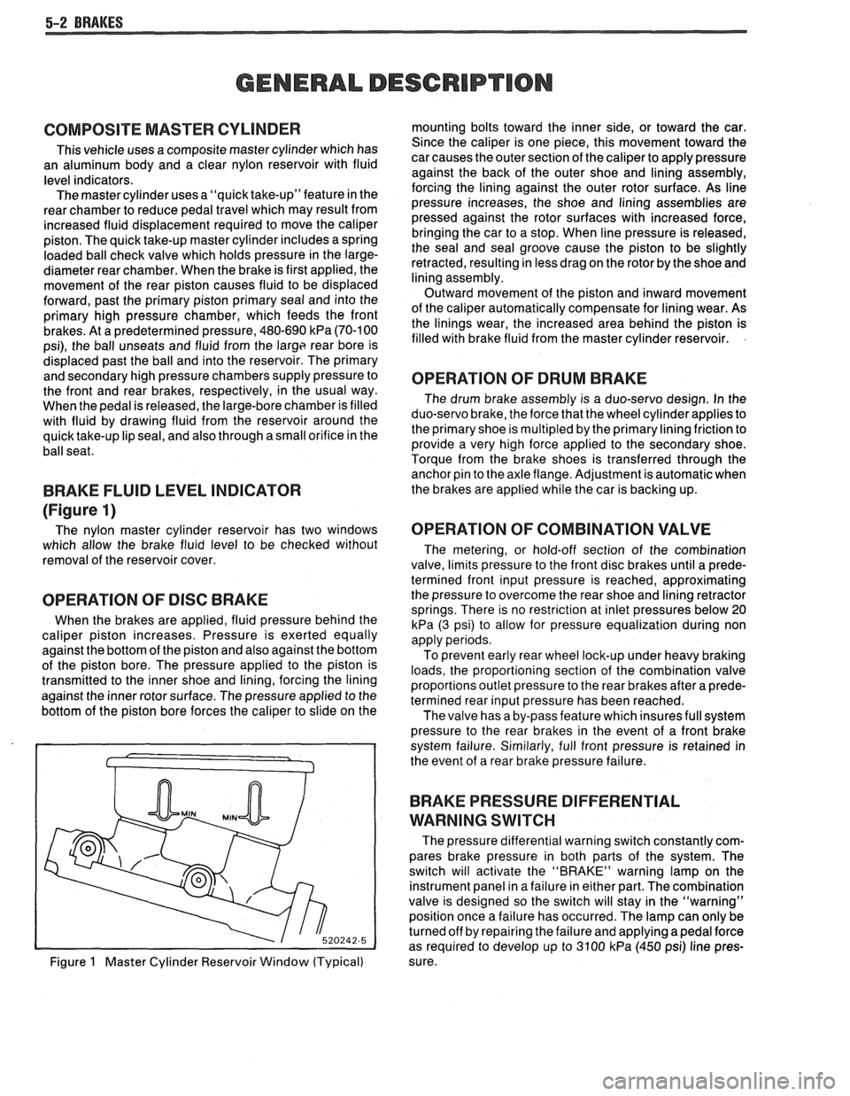
The nylon master cylinder reservoir has two windows
which allow the brake fluid level to be checked without
removal of the reservoir cover.
OPERATION OF DISC BRAKE
When the brakes are applied, fluid pressure behind the
caliper piston increases. Pressure is exerted equally
against the bottom of the piston and also against the bottom
of the piston bore. The pressure applied to the piston is
transmitted to the inner shoe and lining, forcing the lining
against the inner rotor surface. The pressure applied to the
bottom of the piston bore forces the caliper to slide on the
Figure
1 Master Cylinder Reservoir Window (Typical) mounting bolts toward the inner side,
or toward the car.
Since the caliper is one piece, this movement toward the
car causes the outer section of the caliper to apply pressure
against the back of the outer shoe and lining assembly,
forcing the lining against the outer rotor surface. As line
pressure increases, the shoe and lining assemblies are
pressed against the rotor surfaces with increased force,
bringing the car to a stop. When line pressure is released,
the seal and seal groove cause the piston to be slightly
retracted, resulting in less drag on the rotor by the shoe and
lining assembly.
Outward movement of the piston and inward movement
of the caliper automatically compensate for lining wear. As
the linings wear, the increased area behind the piston is
filled with brake fluid from the master cylinder reservoir.
OPERATION OF DRUM BRAKE
The drum brake assembly is a duo-servo design. In the
duo-servo brake, the force that the wheel cylinder applies to
the primary shoe is
multipled by the primary lining friction to
provide a very high force applied to the secondary shoe.
Torque from the brake shoes is transferred through the anchor pin to the axle flange. Adjustment is automatic when
the brakes are applied while the car is backing up.
OPERATION OF COMBINATION VALVE
The metering, or hold-off section of the combination
valve, limits pressure to the front disc brakes until a prede-
termined front input pressure is reached, approximating
the pressure to overcome the rear shoe and lining retractor
springs. There is no restriction at inlet pressures below 20
kPa (3 psi) to allow for pressure equalization during non
apply periods.
To prevent early rear wheel lock-up under heavy braking
loads, the proportioning section of the combination valve
proportions outlet pressure to the rear brakes after a prede-
termined rear input pressure has been reached.
The valve has a by-pass feature which insures full system
pressure to the rear brakes in the event of a front brake
system failure. Similarly, full front pressure is retained in
the event of a rear brake pressure failure.
BRAKE PRESSURE DIFFERENTIAL
WARNING
SWITCH
The pressure differential warning switch constantly com-
pares brake pressure in both parts of the system. The
switch will activate the "BRAKE" warning lamp on the
instrument panel in a failure in either part. The combination
valve is designed so the switch will stay in the "warning"
position once a failure has occurred. The lamp can only be
turned off by repairing the failure and applying a pedal force
as required to develop up to 3100
kPa (450 psi) line pres-
sure.