Page 319 of 962
SECTION 16
DIFFERENTIAL
CONTENTS
16-1. GENERAL DESCRIPTION............................... 16-2
16.2. REMOVAL...........................................16-3
16-3. DISASSEMBLY........................................16-6
16-4. INSPECTION AND ADJUSTMENT OF COMPONENTS.........16-7
16.5. REASSEMBLY.......................................16-13
16-6. INSTALLATION......................................16-15
16-7. MAINTENANCE SERVICES.............................16-16
16-8. RECOMMENDED TORQUE SPECIFICATIONS..............16-16
16-1
Page 333 of 962
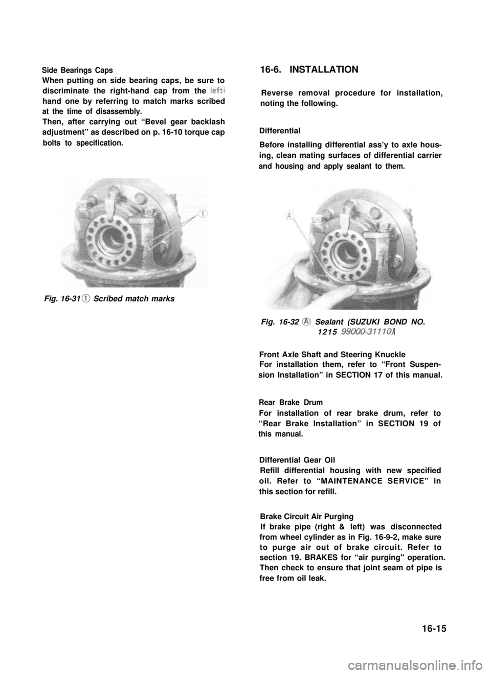
Side Bearings Caps
When putting on side bearing caps, be sure to
discriminate the right-hand cap from the left-
hand one by referring to match marks scribed
at the time of disassembly.
Then, after carrying out “Bevel gear backlash
adjustment” as described on p. 16-10 torque cap
bolts to specification.
16-6. INSTALLATION
Reverse removal procedure for installation,
noting the following.
Differential
Before installing differential ass’y to axle hous-
ing, clean mating surfaces of differential carrier
and housing and apply sealant to them.
Fig. 16-31 0 Scribed match marks
Fig. 16-32 @ Sealant (SUZUKI BOND NO.
1215 99000-31110)
Front Axle Shaft and Steering Knuckle
For installation them, refer to “Front Suspen-
sion Installation” in SECTION 17 of this manual.
Rear Brake Drum
For installation of rear brake drum, refer to
“Rear Brake Installation” in SECTION 19 of
this manual.
Differential Gear Oil
Refill differential housing with new specified
oil. Refer to “MAINTENANCE SERVICE” in
this section for refill.
Brake Circuit Air Purging
If brake pipe (right & left) was disconnected
from wheel cylinder as in Fig. 16-9-2, make sure
to purge air out of brake circuit. Refer to
section 19. BRAKES for “air purging" operation.
Then check to ensure that joint seam of pipe is
free from oil leak.
16-15
Page 334 of 962
16-7. MAINTENANCE SERVICES
Inspection
Inspect differential and differential housing for
evidence of oil leakage.
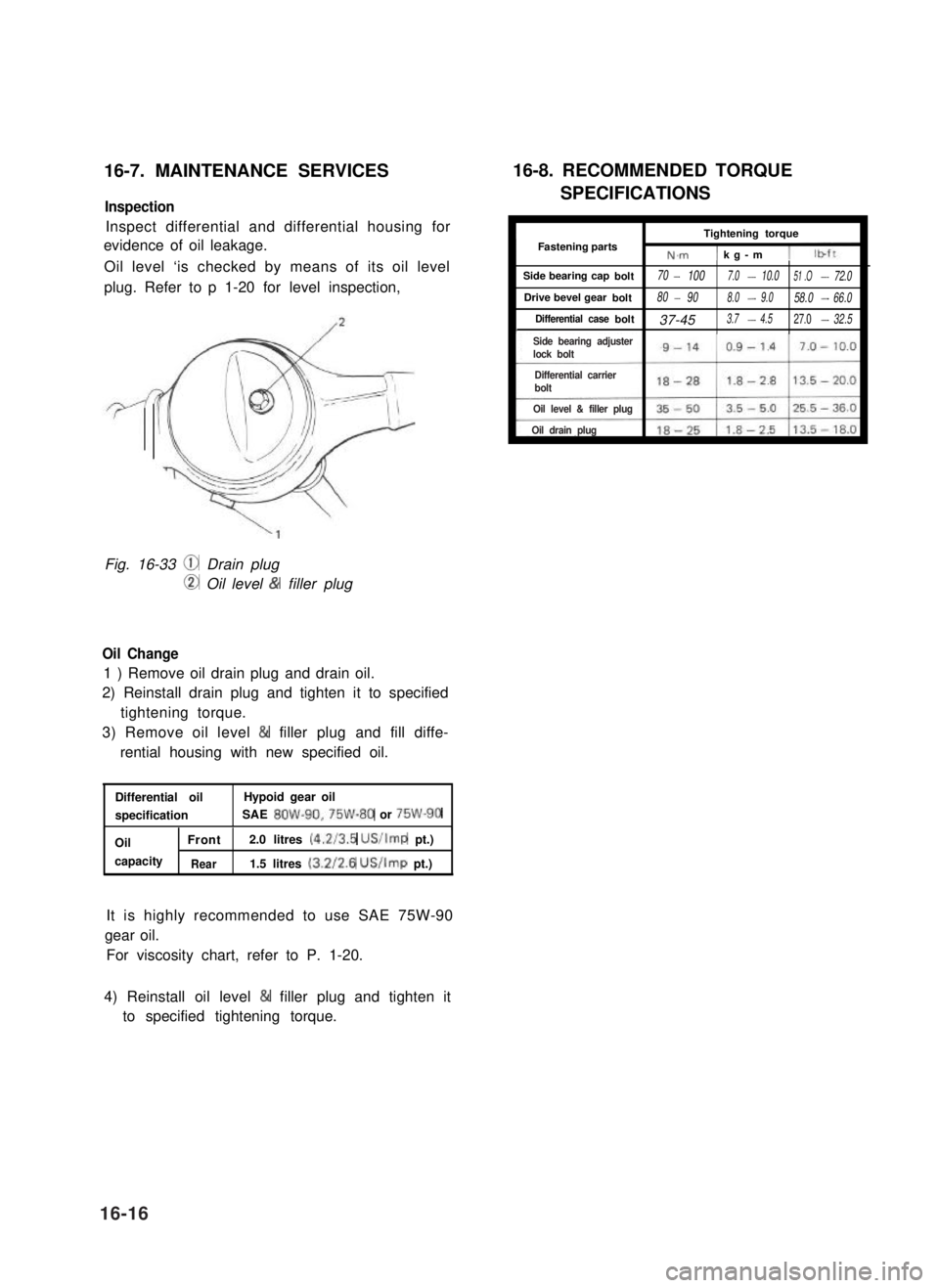
Oil level ‘is checked by means of its oil level
plug. Refer to p 1-20 for level inspection,
Fig. 16-33 @ Drain plug
CD Oil level & filler plug
Oil Change
1 ) Remove oil drain plug and drain oil.
2) Reinstall drain plug and tighten it to specified
tightening torque.
3) Remove oil level & filler plug and fill diffe-
rential housing with new specified oil.
Differential oilHypoid gear oil
specificationSAE 8OW-90,75W-80 or 75W-90
OilFront2.0 litres (4.2/3.5 US/Imp pt.)
capacityRear1.5 litres (3.2/2.6 US/Imp pt.)
It is highly recommended to use SAE 75W-90
gear oil.
For viscosity chart, refer to P. 1-20.
16-8. RECOMMENDED TORQUE
SPECIFICATIONS
ITightening torqueI
IFastening partsN.m1 kg-m 11
Side bearing capbolt70- 1007.0-10.051 .O-72.0
Drive bevel gearbolt80- 908.0-9.058.0-66.0
Differential casebolt37-453.7-4.527.0-32.5I
4) Reinstall oil level & filler plug and tighten it
to specified tightening torque.
16-16
Side bearing adjusterlock bolt
Differential carrier bolt
Oil level & filler plug
Oil drain plug
Page 335 of 962
SECTION 17
SUSPENSION
CONTENTS
17-1. FRONT SUSPENSION. . . . . . . . . . . . . . . . . . . . . . . . . . . . . . . . . . . . . . 17-2
17-2. REAR SUSPENSION . . . . . . . . . . . . . . . . . . . . . . . . . . . . . . . . . . . . . . 17-15
17-3. MAINTENANCE SERVICES.. . . . . . . . . . . . . . . . . . . . . . . . . . . . . . . 17-20
17-4. RECOMMENDED TORQUE SPECIFICATIONS.. . . . . . . . . . . . . . . . 17-26
17-5. FRONT FREE WHEELING HUB (OPTIONAL) . . . . . . . . . . . . . . . . . 17-27
NOTE:
l All suspension fasteners are an important attaching part in that it could affect the
performance of vital parts and systems, and/or could result in major repair expense.
They must be replaced with one of the same part number or with an equivalent part if
replacement becomes necessary. Do not use a replacement part of lesser quality or
substitute design. Torque values must be used as specified during reassembly to assure
proper retention of this part.
l Never attempt to heat, quench or straighten any suspension part. Replace it with a new
part, or damage to the part may result.
l The leaf spring number or shape shown in this manual may differ from the car being
actually serviced, depending on specification.
17-1
Page 354 of 962
17-3. MAINTENANCE SERVICES
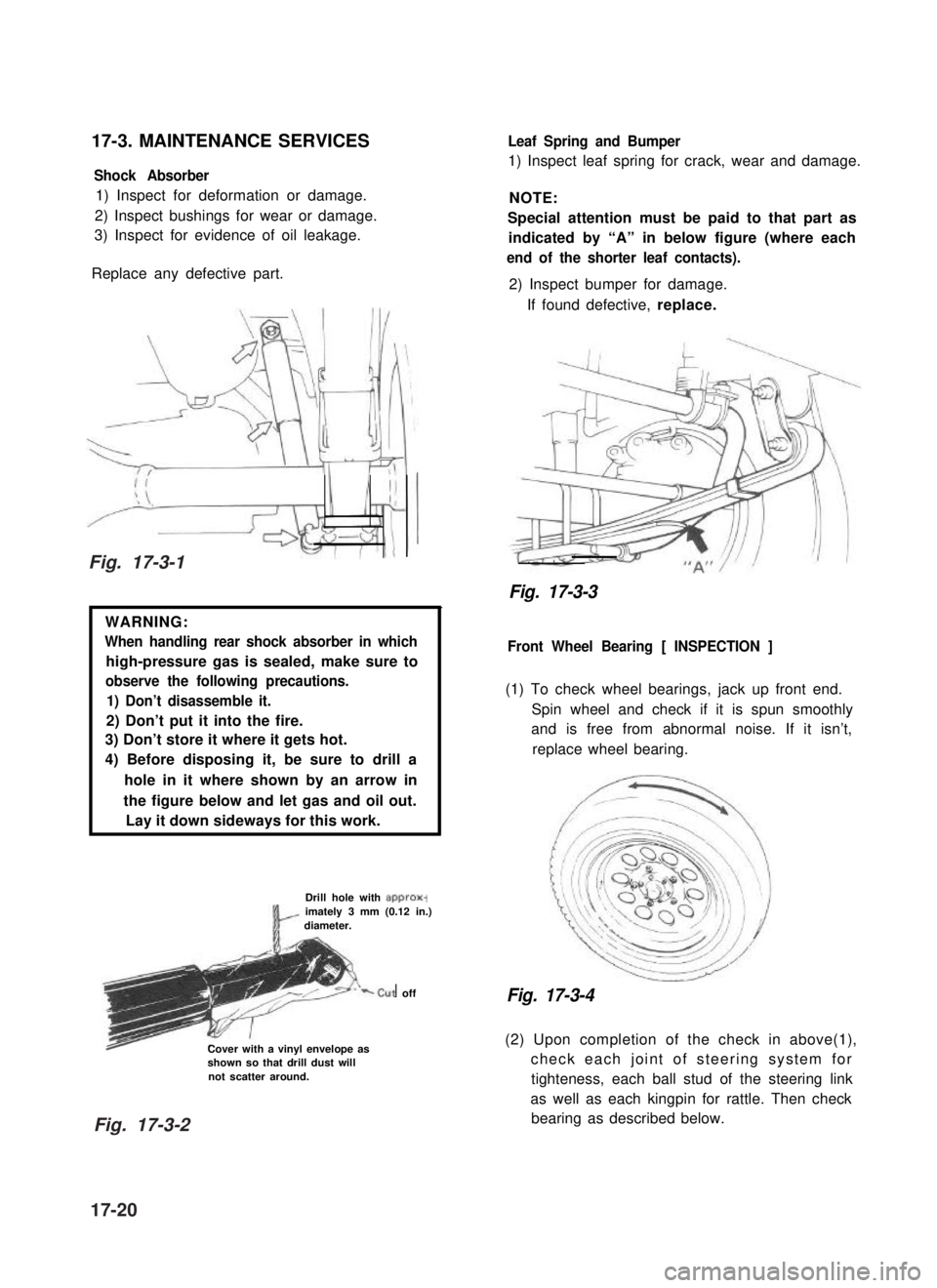
Shock Absorber
1) Inspect for deformation or damage.
2) Inspect bushings for wear or damage.
3) Inspect for evidence of oil leakage.
Replace any defective part.
WARNING:
When handling rear shock absorber in which
high-pressure gas is sealed, make sure to
observe the following precautions.
1) Don’t disassemble it.
2) Don’t put it into the fire.
3) Don’t store it where it gets hot.
4) Before disposing it, be sure to drill a
hole in it where shown by an arrow in
the figure below and let gas and oil out.
Lay it down sideways for this work.
Drill hole with approx-imately 3 mm (0.12 in.)diameter.
‘-cut off
Cover with a vinyl envelope asshown so that drill dust willnot scatter around.
Leaf Spring and Bumper
1) Inspect leaf spring for crack, wear and damage.
NOTE:
Special attention must be paid to that part as
indicated by “A” in below figure (where each
end of the shorter leaf contacts).
2) Inspect bumper for damage.
If found defective, replace.
Fig. 17-3-3
Front Wheel Bearing [ INSPECTION ]
(1) To check wheel bearings, jack up front end.
Spin wheel and check if it is spun smoothly
and is free from abnormal noise. If it isn’t,
replace wheel bearing.
Fig. 17-3-4
(2) Upon completion of the check in above(1),
check each joint of steering system for
tighteness, each ball stud of the steering link
as well as each kingpin for rattle. Then check
bearing as described below.
Fig. 17-3-1
Fig. 17-3-2
17-20
Page 361 of 962
17-5. FRONT FREE WHEELING HUB (OPTIONAL)
General Description
This section describes operation, installation and maintenance of free wheeling hub. Be sure to refer to
this section carefully for proper service.
Operation
A free wheeling hub should be fitted onto each of the right and left front wheel hubs. The free wheeling
hub has a knob and two embossed marks,“FREE” and “LOCK”. When the knob is set to the “FREE”
position, the axle shaft and wheel are disconnected and the revolution of the front wheels becomes free.
When it is set to the “LOCK” position, the axle shaft and wheel are connected.
“FREE” positionWasher 6od/ Cover hs’Y
-/ /Ass’y/
Snap ring
B
iAxle shaft
Fig. 17-5-1 Hub
“LOCK” position
Fig. 17-5-2
For their usage, refer to Owner’s Manual supplied with the car.
CAUTION :
Both of the right and left wheeling hub knobs must be set to the same position (either FREE or
LOCK). Don’t set one to ‘FREE” and the other to “LOCK” positions.
17-27
Page 363 of 962
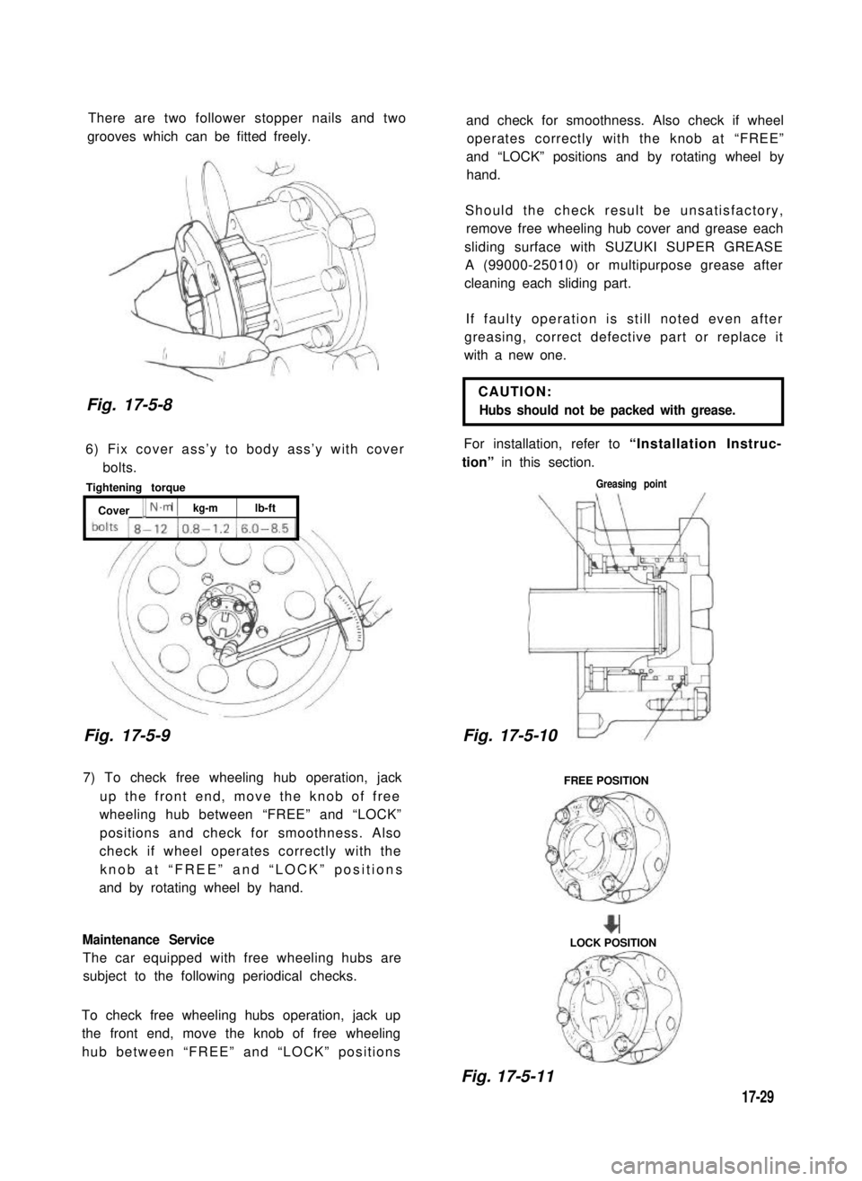
There are two follower stopper nails and two
grooves which can be fitted freely.
Fig. 17-5-8
6) Fix cover ass’y to body ass’y with cover
bolts.
Tightening torque
[ Cover [ N.m 1kg-mlb-ft
Fig. 17-5-9
7) To check free wheeling hub operation, jack
up the front end, move the knob of free
wheeling hub between “FREE” and “LOCK”
positions and check for smoothness. Also
check if wheel operates correctly with the
knob at “FREE” and “LOCK” positions
and by rotating wheel by hand.
Maintenance Service
The car equipped with free wheeling hubs are
subject to the following periodical checks.
To check free wheeling hubs operation, jack up
the front end, move the knob of free wheeling
hub between “FREE” and “LOCK” positions
and check for smoothness. Also check if wheel
operates correctly with the knob at “FREE”
and “LOCK” positions and by rotating wheel by
hand.
Should the check result be unsatisfactory,
remove free wheeling hub cover and grease each
sliding surface with SUZUKI SUPER GREASE
A (99000-25010) or multipurpose grease after
cleaning each sliding part.
If faulty operation is still noted even after
greasing, correct defective part or replace it
with a new one.
CAUTION:
Hubs should not be packed with grease.
For installation, refer to “Installation Instruc-
tion” in this section.
Greasing point
17-5-
FREE POSITION
+LOCK POSITION
Fig. 17-5-11
17-29
Fig. 17-5-10
Page 364 of 962
SECTION 18
STEERING SYSTEM
CONTENTS
18-1.GENERAL DESCRIPTION............................... 18-4
18-2.SPECIFICATIONS AND DATA............................18-4
STEERING GEAR BOX CONSTRUCTION AND OPERATION...18-5
18-4.REMOVAL...........................................18-6
18-5.INSPECTION OF COMPONENTS..........................
CHECKING STEERING COLUMN FOR ACCIDENT DAMAGE.
18-7.IMPORTANT STEPS IN REINSTALLATION..................
18-8.WHEEL ALIGNMENT..................................
18-9.MAINTENANCE SERVICES.............................
18-10. RECOMMENDED TORQUE SPECIFICATIONS..............
NOTE:
All steering system fasteners are important parts in that they could affect the performance
of vital parts and systems, and/or could result in major repair expense. They must be
replaced with one of the same part number or with an equivalent part if replacement
becomes necessary. Do not use a replacement part of lesser quality or substitute design.
Torque values must be used as specified during reassembly to assure proper retention of
this part.
18-1
18-3.
18-9
18-12
18-11
18-16
18-18
18-22
18-6.