1987 SUZUKI GRAND VITARA maintenance
[x] Cancel search: maintenancePage 34 of 962
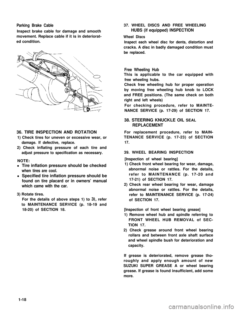
Parking Brake Cable
Inspect brake cable for damage and smooth
movement. Replace cable if it is in deteriorat-
ed condition.
36. TIRE INSPECTION AND ROTATION
1) Check tires for uneven or excessive wear, or
damage. If defective, replace.
2) Check inflating pressure of each tire and
adjust pressure to specification as necessary.
NOTE:
l Tire inflation pressure should be checked
when tires are cool.
l Specified tire inflation pressure should be
found on tire placard or in owners’ manual
which came with the car.
3) Rotate tires.
For the details of above steps 1) to 3), refer
to MAINTENANCE SERVICE (p. 18-19 and
18-20) of SECTION 18.
37. WHEEL DISCS AND FREE WHEELING
HUBS (if equipped) INSPECTION
Wheel Discs
Inspect each wheel disc for dents, distortion and
cracks. A disc in badly damaged condition must
be replaced.
Free Wheeling Hub
This is applicable to the car equipped with
free wheeling hubs.
Check free wheeling hub for proper operation
by moving free wheeling hub knob to LOCK
and FREE positions. (The same check on both
right and left wheels)
For checking procedure, refer to MAINTE-
NANCE SERVICE (p. 17-29) of SECTION 17.
38. STEERING KNUCKLE OIL SEAL
REPLACEMENT
For replacement procedure, refer to MAIN-
TENANCE SERVICE (p. 17-23) of SECTION
17.
39. WHEEL BEARING INSPECTION
[Inspection of wheel bearing]
1) Check front wheel bearing for wear, damage,
abnormal noise or rattles. For the details,
refer to MAINTENANCE (p. 17-20 and
17-21) of SECTION 17.
2) Check rear wheel bearing for wear, damage
abnormal noise or rattles. For the details,
refer to MAINTENANCE SERVICE (p. 17-24)
of SECTION 17.
[Inspection of front wheel bearing grease]
1) Remove wheel hub and spindle referring to
FRONT WHEEL HUB REMOVAL of SEC-
TION 17.
2) Check grease around front wheel bearing
rollars and between front axle shaft surface
and wheel spindle bush for deterioration and
capacity.
If grease is deteriorated, remove grease tho-
roughly and apply enough amount of new
SUZUKI SUPER GREASE A or wheel bearing
grease. If grease is found insufficient, add some
more.
1-18
Page 35 of 962
3) Install spindle, bearings, wheel hub, bearing
nut and brake disc referring to INSTALLA-
TION (p. 17-12) of SECTION 17.
4) Adjust bearing preload and then tighten
bearing lock nut to specification. Refer to
MAINTENANCE (p. 17-21) of SECTION 17.
5) Install drive flange or free wheeling hub (if
equipped), brake caliper with mounting and
wheel referring to INSTALLATION (p. 17-
12) of SECTION 17.
For tightening torque of each bolt and nut,
refer to torque table (p. 17-26) of SECTION
17.
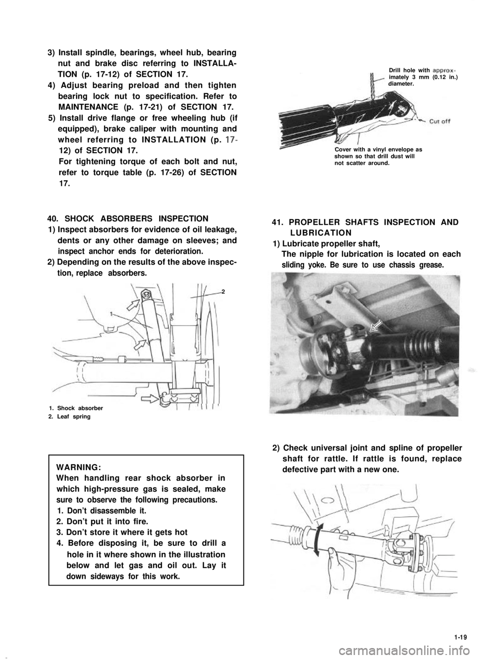
40. SHOCK ABSORBERS INSPECTION
1) Inspect absorbers for evidence of oil leakage,
dents or any other damage on sleeves; and
inspect anchor ends for deterioration.
2) Depending on the results of the above inspec-
tion, replace absorbers.
2
1. Shock absorber
2. Leaf spring
WARNING:
When handling rear shock absorber in
which high-pressure gas is sealed, make
sure to observe the following precautions.
1. Don’t disassemble it.
2. Don’t put it into fire.
3. Don’t store it where it gets hot
4. Before disposing it, be sure to drill a
hole in it where shown in the illustration
below and let gas and oil out. Lay it
down sideways for this work.
Drill hole with approx-imately 3 mm (0.12 in.)diameter.
Cover with a vinyl envelope asshown so that drill dust willnot scatter around.
41. PROPELLER SHAFTS INSPECTION AND
LUBRICATION
1) Lubricate propeller shaft,
The nipple for lubrication is located on each
sliding yoke. Be sure to use chassis grease.
2) Check universal joint and spline of propeller
shaft for rattle. If rattle is found, replace
defective part with a new one.
1-19
Page 37 of 962
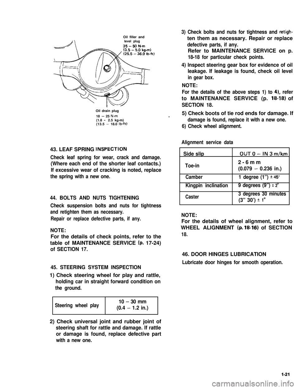
Oil filler andlevel plug
Oil drain plug
18 - 25 N.m(1.8 - 2.5 kg-m)(13.5 - 18.0 lb-ft)
43. LEAF SPRING lNSPECTlON
Check leaf spring for wear, crack and damage.
(Where each end of the shorter leaf contacts.)
If excessive wear of cracking is noted, replace
the spring with a new one.
44. BOLTS AND NUTS TIGHTENING
Check suspension bolts and nuts for tightness
and retighten them as necessary.
Repair or replace defective parts, if any.
NOTE:
For the details of check points, refer to the
table of MAINTENANCE SERVICE (p. 17-24)
of SECTION 17.
45. STEERING SYSTEM INSPECTION
1) Check steering wheel for play and rattle,
holding car in straight forward condition on
the ground.
Steering wheel play10 - 30 mm
(0.4 - 1.2 in.)
3) Check bolts and nuts for tightness and retigh-
ten them as necessary. Repair or replace
defective parts, if any.
Refer to MAINTENANCE SERVICE on p.
18-18 for particular check points.
4) Inspect steering gear box for evidence of oil
leakage. If leakage is found, check oil level
in gear box.
NOTE:
For the details of the above steps 1) to 41, refer
to MAINTENANCE SERVICE (p. 18-18) of
SECTION 18.
.5) Check boots of tie rod ends for damage. If
damage is found, replace it with a new one.
6) Check wheel alignment.
Alignment service data
Side slipOUTO-IN3m/km
Toe-in2-6mm
(0.079 - 0.236 in.)
Camber1 degree (1”) *45’
Kingpin inclination 9 degrees (9”) f 2’
Caster3 degrees 30 minutes
(3” 30’) f I0
NOTE:
For the details of wheel alignment, refer to
WHEEL ALIGNMENT (p. 18-16) of SECTION
18.
46. DOOR HINGES LUBRICATION
Lubricate door hinges for smooth operation.
2) Check universal joint and rubber joint of
steering shaft for rattle and damage. If rattle
or damage is found, replace defective part
with a new one.
1-21
Page 58 of 962

3-1.
3-2.
3-3.
3-5.
3-6.
3-7.
3-8.
3-9.
SECTION 3
ENGINE
CONTENTS
GENERAL DESCRIPTION.................................... 3-2
ENGINE SERVICES NOT REQUIRING ENGINE REMOVAL...... 3-5
ENGINE REMOVAL.......................................3-6
ENGINE DISASSEMBLY.................................. 3-9
INSPECTION OF ENGINE COMPONENTS....................3-17
ENGINE REASSEMBLY...................................3-35
ENGINE INSTALLATION.................................3-53
ENGINE MAINTENANCE SERVICE.........................3-53
RECOMMENDED TORQUE SPECIFICATIONS.................3-58
3-4.
3-1
3
Page 110 of 962
3-7. ENGINE INSTALLATION
1) Lower engine with transmission into vehicle,
but do not remove lifting device.
2) Tighten engine mounting bracket bolts
(right and left) and transmission mounting
bolts to specification. Refer to p. 3-58.
3) Remove lifting device.
4) Reverse removal procedures for installation
of remainder.
5) Adjust accelerator cable play and clutch
cable play.
6) Connect vacuum hoses securely. Refer to
section 5 “EMISSION CONTROL SYSTEM”
for correct connection.
7) Connect wire harnesses and couplers secure-
IY.
8) Tighten bolts and nuts to specified torque.
For individual specification, refer to each
section.
9) Fill specified amount of specified trans-
mission oil and engine oil. For the detail,
refer to SECTION 1 PERIODIC MAINTE-
NANCE SERVICE of this manual.
10) After adjusting water pump belt tension to
specification, fill specified amount of engine
cooling water.
11) Before starting engine, check again to ensure
that all parts once disassembled or discon-
nected are back in place securely.
12)Start engine and check ignition timing. If
it is not to specified timing, adjust it, referr-
ing to SECTION 8 of this manual.
13) After engine is started, check for oil leak,
abnormal noise and other malcondition.
Also, check each part for operation.
3-8. ENGINE MAINTENANCE SERVICE
Fan Belt
Adjust belt tension as outlined in SECTION 6
ENGINE COOLING SYSTEM (p. 6-10).
Ignition Timing
Refer to IGNITION TIMING, Page 8-9.
Carburetor
fidjustments to be made are detailed in SEC-
TION 4 (p. 4-19).
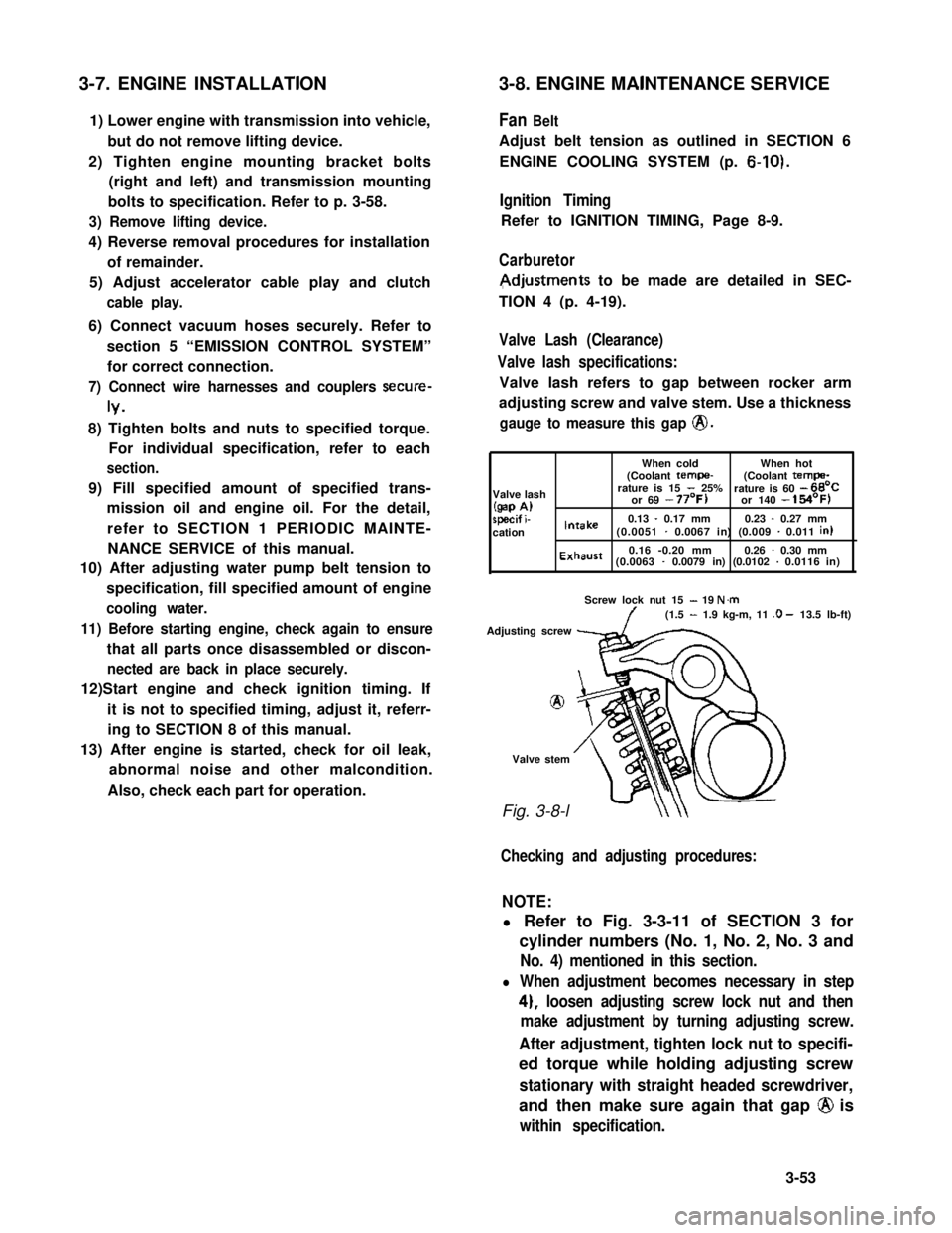
Valve Lash (Clearance)
Valve lash specifications:
Valve lash refers to gap between rocker arm
adjusting screw and valve stem. Use a thickness
gauge to measure this gap @.
When coldWhen hot(Coolant tempe-(Coolant tempa-
Valve lashrature is 15 - 25%rature is 60 - 66’C
(gap A)or 69 - 77’F)or 140 - 154’F)
specif i-0.13 - 0.17 mm0.23 - 0.27 mmcationIntake(0.0051 - 0.0067 in) (0.009 - 0.011 in)
Exhaust0.16 -0.20 mm0.26 - 0.30 mm(0.0063 - 0.0079 in) (0.0102 - 0.0116 in)
Screw lock nut 15 - 19 N.m(1.5 - 1.9 kg-m, 11 .O - 13.5 lb-ft)
Adjusting screw
8
Valve stem
Fig. 3-8-l
Checking and adjusting procedures:
NOTE:
l Refer to Fig. 3-3-11 of SECTION 3 for
cylinder numbers (No. 1, No. 2, No. 3 and
No. 4) mentioned in this section.
l When adjustment becomes necessary in step
4), loosen adjusting screw lock nut and then
make adjustment by turning adjusting screw.
After adjustment, tighten lock nut to specifi-
ed torque while holding adjusting screw
stationary with straight headed screwdriver,
and then make sure again that gap @ is
within specification.
3-53
Page 116 of 962

SECTION 4
FUEL SYSTEM
CONTENTS
4-1.CARBURETOR.............................................4-2
GENERAL DESCRIPTION.................................4-2
REMOVAL AND INSTALLATION...........................4-12
UNIT REPAIR OVERHAUL...............................4-13
MAINTENANCE SERVICES...............................4-19
4-2.AIR CLEANER...........................................4-29
GENERAL DESCRIPTION.................................4-29
MAINTENANCE SERVICES...............................4-29
4-3.FUEL PUMP, FILTER AND LINES...........................4-31
GENERAL DESCRIPTION.................................4-31
REMOVAL AND INSTALLATION...........................4-33
MAINTENANCE SERVICES...............................4-35
4-4.ACCELERATOR PEDAL...................................4-36
CAUTION:
THE ENGINE OF THIS VEHICLE REQUIRED THE USE OF UNLEADED FUEL ONLY.
USE OF LEADED AND/OR LOW LEAD FUEL CAN RESULT IN ENGINE DAMAGE AND RE-
DUCE THE EFFECTIVENESS OF THE EMISSION CONTROL SYSTEMS.
4-1
4
Page 134 of 962
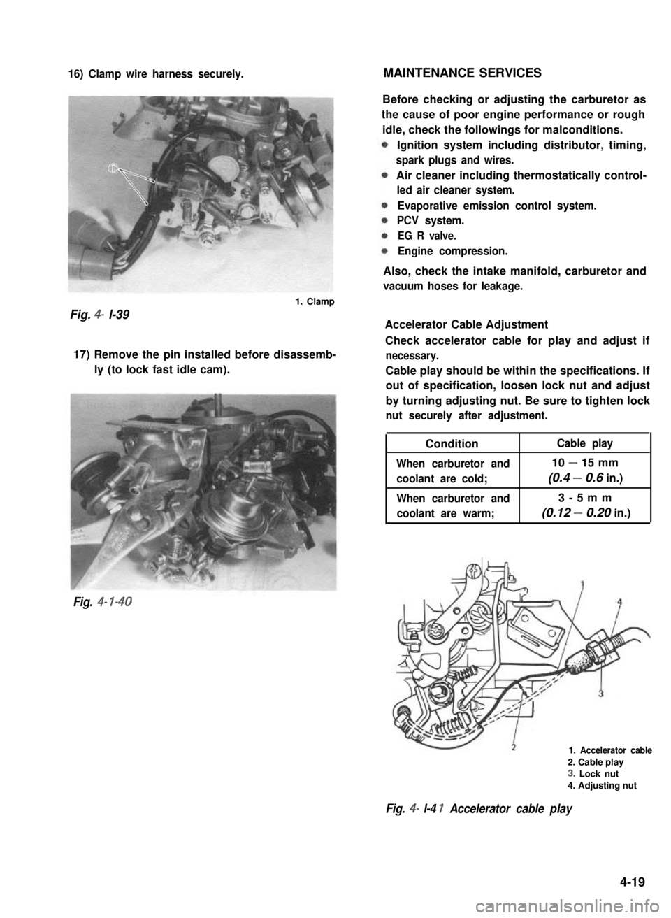
16) Clamp wire harness securely.MAINTENANCE SERVICES
Fig. 4- l-39
1. Clamp
17) Remove the pin installed before disassemb-
ly (to lock fast idle cam).
Fig. 4- l-40
Before checking or adjusting the carburetor as
the cause of poor engine performance or rough
idle, check the followings for malconditions.
Ignition system including distributor, timing,
spark plugs and wires.
Air cleaner including thermostatically control-
led air cleaner system.
Evaporative emission control system.
PCV system.
EG R valve.
Engine compression.
Also, check the intake manifold, carburetor and
vacuum hoses for leakage.
Accelerator Cable Adjustment
Check accelerator cable for play and adjust if
necessary.
Cable play should be within the specifications. If
out of specification, loosen lock nut and adjust
by turning adjusting nut. Be sure to tighten lock
nut securely after adjustment.
Condition
When carburetor and
coolant are cold;
When carburetor and
coolant are warm;
Cable play
10 - 15 mm
(0.4 - 0.6 in.)
3-5mm
(0.12 - 0.20 in.)
1. Accelerator cable
2. Cable play
3. Lock nut
4. Adjusting nut
Fig. 4- l-4 1 Accelerator cable play
4-19
Page 141 of 962
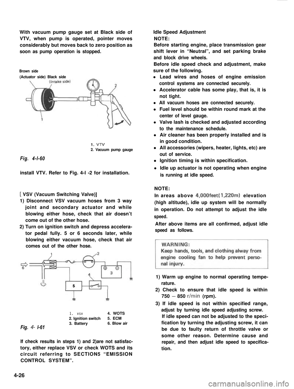
With vacuum pump gauge set at Black side of
VTV, when pump is operated, pointer moves
considerably but moves back to zero position as
soon as pump operation is stopped.
Brown side
(Actuator side) Black side
Fig. 4-l-60
1. VTV
2. Vacuum pump gauge
install VTV. Refer to Fig. 4-l -2 for installation.
[ VSV (Vacuum Switching Valve)]
1) Disconnect VSV vacuum hoses from 3 way
joint and secondary actuator and while
blowing either hose, check that air doesn’t
come out of the other hose.
2) Turn on ignition switch and depress accelera-
tor pedal fully. 5 or 6 seconds later, while
blowing either vacuum hose, check that air
comes out of the other hose.
J5
Fig. 4- l-61
1I
1. vsv4. WOTS
2. Ignition switch5. ECM
3. Battery6. Blow air
If check results in steps 1) and 2)are not satisfac-
tory, either replace VSV or check WOTS and its
circuit referring to SECTION5 “EMISSION
CONTROL SYSTEM”.
Idle Speed Adjustment
NOTE:
Before starting engine, place transmission gear
shift lever in “Neutral”, and set parking brake
and block drive wheels.
Before idle speed check and adjustment, make
sure of the following.
l Lead wires and hoses of engine emission
control systems are connected securely.
l Accelerator cable has some play, that is, it is
not tight.
l All vacuum hoses are connected securely.
l Fuel level should be within round mark at the
center of level gauge.
l Valve lash is checked and adjusted according
to the maintenance schedule.
l Air cleaner has been properly installed and is
in good condition.
l All accessories (wipers, heater, lights, etc) are
out of service.
l Ignition timing is within specification.
l Idle up actuator is not operating when engine
is running at idle speed.
NOTE:
In areas above 4,00Ofeet( 1,220m) elevation
(high altitude), idle up system will be normally
in operation. Do not attempt to adjust the idle
speed.
After above items are all confirmed, adjust idle
speed as follows.
1) Warm up engine to normal operating tempe-
rature.
2) Check to ensure that idle speed is within
750 - 850 r/min (rpm).
3) If idle speed is not within specified range,
adjust by turning idle speed adjusting screw.
If idle speed can not be adjusted to the speci-
fication by turning the adjusting screw, it can
be due to faulty return of throttle valve or
some other reason. Determine cause and
repair, and then adjust idle speed to specifica-
tion.
4-26