1987 SUZUKI GRAND VITARA maintenance
[x] Cancel search: maintenancePage 381 of 962
189. MAINTENANCE SERVICES
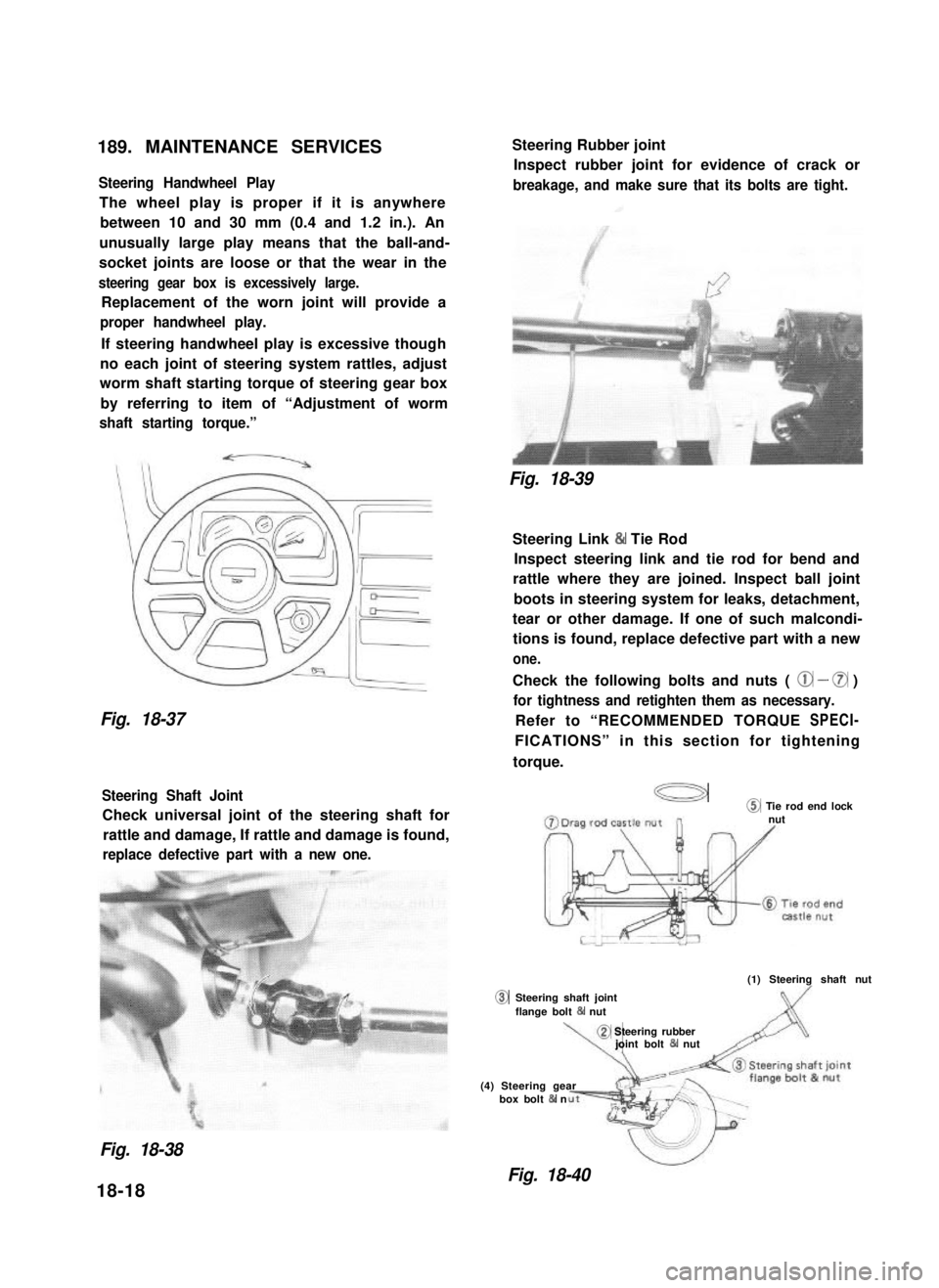
Steering Handwheel Play
The wheel play is proper if it is anywhere
between 10 and 30 mm (0.4 and 1.2 in.). An
unusually large play means that the ball-and-
socket joints are loose or that the wear in the
steering gear box is excessively large.
Replacement of the worn joint will provide a
proper handwheel play.
If steering handwheel play is excessive though
no each joint of steering system rattles, adjust
worm shaft starting torque of steering gear box
by referring to item of “Adjustment of worm
shaft starting torque.”
Fig. 18-37
Steering Shaft Joint
Check universal joint of the steering shaft for
rattle and damage, If rattle and damage is found,
replace defective part with a new one.
0
Steering Rubber joint
Inspect rubber joint for evidence of crack or
breakage, and make sure that its bolts are tight.
Fig. 18-39
Steering Link & Tie Rod
Inspect steering link and tie rod for bend and
rattle where they are joined. Inspect ball joint
boots in steering system for leaks, detachment,
tear or other damage. If one of such malcondi-
tions is found, replace defective part with a new
one.
Check the following bolts and nuts ( @ - 0 )
for tightness and retighten them as necessary.
Refer to “RECOMMENDED TORQUE SPECI-
FICATIONS” in this section for tightening
torque.
a@ Tie rod end locknut
(1) Steering shaft nut
Steering shaft jointflange bolt 84 nut
\,
@ Steering rubberjoint bolt & nut
(4) Steering gearbox bolt & n
Fig. 18-38
Fig. 18-40
18-18
Page 386 of 962
SECTION 19
BRAKES
CONTENTS
19-1. GENERAL DESCRIPTION................................. 19-2
19-2. FRONT DISC BRAKE..................................... 19-14
19-3. REAR DRUM BRAKE..................................... 19-20
19-4. MASTER CYLINDER..................................... 19-27
19-5. BRAKE BOOSTER....................................... 19-30
19-6. PARKING BRAKE........................................ 19-38
19-7. BRAKE PIPES AND HOSES . . . . . . . . . . . . . . . . . . . . . . . . . . . . . . . 19-39
19-8. MAINTENANCE SERVICE . . . . . . . . . . . . . . . . . . . . . . . . . . . . . . . . 19-42
19-9. TORQUE SPECIFICATION.. . . . . . . . . . . . . . . . . . . . . . . . . . . . . . . 19-49
NOTE:
All brake fasteners are important attaching parts in that they could affect the performance
of vital parts and systems, and/or could result in major repair expense. They must be
replaced with one of same part number or with an equivalent part if replacement becomes
necessary. Do not use a replacement part of lesser quality or substitute design. Torque
values must be used as specified during reassembly to assure proper retention of all parts.
There is to be no welding as it may result in extensive damage and weakening of the
metal.
WARNING:
When servicing wheel brake parts, do not create dust by grinding, sanding brake linings,
or by cleaning wheel brake parts with a dry brush or with compressed air. Many wheel
brake parts contain asbestos fibers which can become airborned if dust is created dur-
ing servicing. Breathing dust containing asbestos fibers may cause serious bodily harm.
A water dampened cloth or water based solution should be used to remove any dust
on brake parts. Equipment is commercially available to perform this washing function.
These wet methods will prevent asbestos fibers from becoming airborne.
19-1
Page 427 of 962
19-8. MAINTENANCE SERVICE
ROAD TESTING BRAKES
Brakes should be tested on dry, clean, smooth
and reasonably level roadway which is not
crowned. Road test brakes by making brake
applications with both light and heavy pedal
forces at various speeds to determine if the car
stops evenly and effectively.
Also drive car to see if it leads to one side or the
other without brake application. If it does,
check tire pressure, front end alignment and
front suspension attachments for looseness.
See diagnosis chart for other causes.
BRAKE FLUID LEAKS
Check master cylinder fluid levels. While a slight
drop in reservoir level does result from normal
lining wear, an abnormally low level indicates a
leak in the system.In such a case, check the
entire brake system for leakage. If even a slight
evidence of leakage is noted, the cause should be
corrected or defective parts should be replaced.
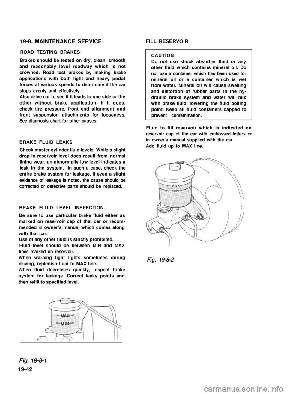
BRAKE FLUID LEVEL INSPECTION
Be sure to use particular brake fluid either as
marked on reservoir cap of that car or recom-
mended in owner’s manual which comes along
with that car.
Use of any other fluid is strictly prohibited.
Fluid level should be between MIN and MAX
lines marked on reservoir.
When warning light lights sometimes during
driving, replenish fluid to MAX line.
When fluid decreases quickly, inspect brake
system for leakage. Correct leaky points and
then refill to specified level.
FILL RESERVOIR
CAUTION:
Do not use shock absorber fluid or any
other fluid which contains mineral oil. Do
not use a container which has been used for
mineral oil or a container which is wet
from water. Mineral oil will cause swelling
and distortion of rubber parts in the hy-
draulic brake system and water will mix
with brake fluid, lowering the fluid boiling
point. Keep all fluid containers capped to
prevent contamination.
Fluid to fill reservoir which is indicated on
reservoir cap of the car with embossed letters or
in owner’s manual supplied with the car.
Add fluid up to MAX line.
Fig. 19-8-2
Fig. 19-8-1
19-42
Page 429 of 962
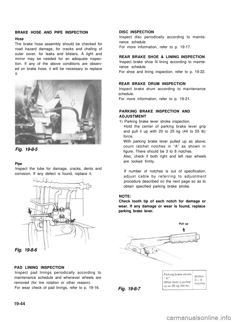
BRAKE HOSE AND PIPE INSPECTION
Hose
The brake hose assembly should be checked for
road hazard damage, for cracks and chafing of
outer cover, for leaks and blisters. A light and
mirror may be needed for an adequate inspec-
tion. If any of the above conditions are observ-
ed on brake hose, it will be necessary to replace
it.
DISC INSPECTION
Inspect disc periodically according to mainte-
nance schedule.
For more information, refer to p. 19-17.
REAR BRAKE SHOE & LINING INSPECTION
Inspect brake shoe & lining according to mainte-
nance schedule.
For shoe and lining inspection, refer to p. 19-22.
Fig. 19-8-5
Pipe
Inspect the tube for damage, cracks, dents and
corrosion. If any defect is found, replace it.
Fig. 19-8-6\ ’
PAD LINING INSPECTION
Inspect pad linings periodically according to
maintenance schedule and whenever wheels are
removed (for tire rotation or other reason).
For wear check of pad linings, refer to p. 19-16.
REAR BRAKE DRUM INSPECTION
Inspect brake drum according to maintenance
schedule.
For more information, refer to p. 19-21.
PARKING BRAKE INSPECTION AND
ADJUSTMENT
1) Parking brake lever stroke inspection.
Hold the center of parking brake lever grip
and pull it up with 20 to 25 kg (44 to 55 lb)
force.
With parking brake lever pulled up as above,
count ratchet notches in “A” as shown in
figure. There should be 3 to 8 notches.
Also, check if both right and left rear wheels
are locked firmly.
If number of notches is out of specification,
adjust cable by referring to adjustment
procedure described on the next page so as to
obtain specified parking brake stroke.
NOTE:
Check tooth tip of each notch for damage or
wear. If any damage or wear is found, replace
parking brake lever.
Pull up
4
Fig. 19-8-7
19-44
Page 453 of 962
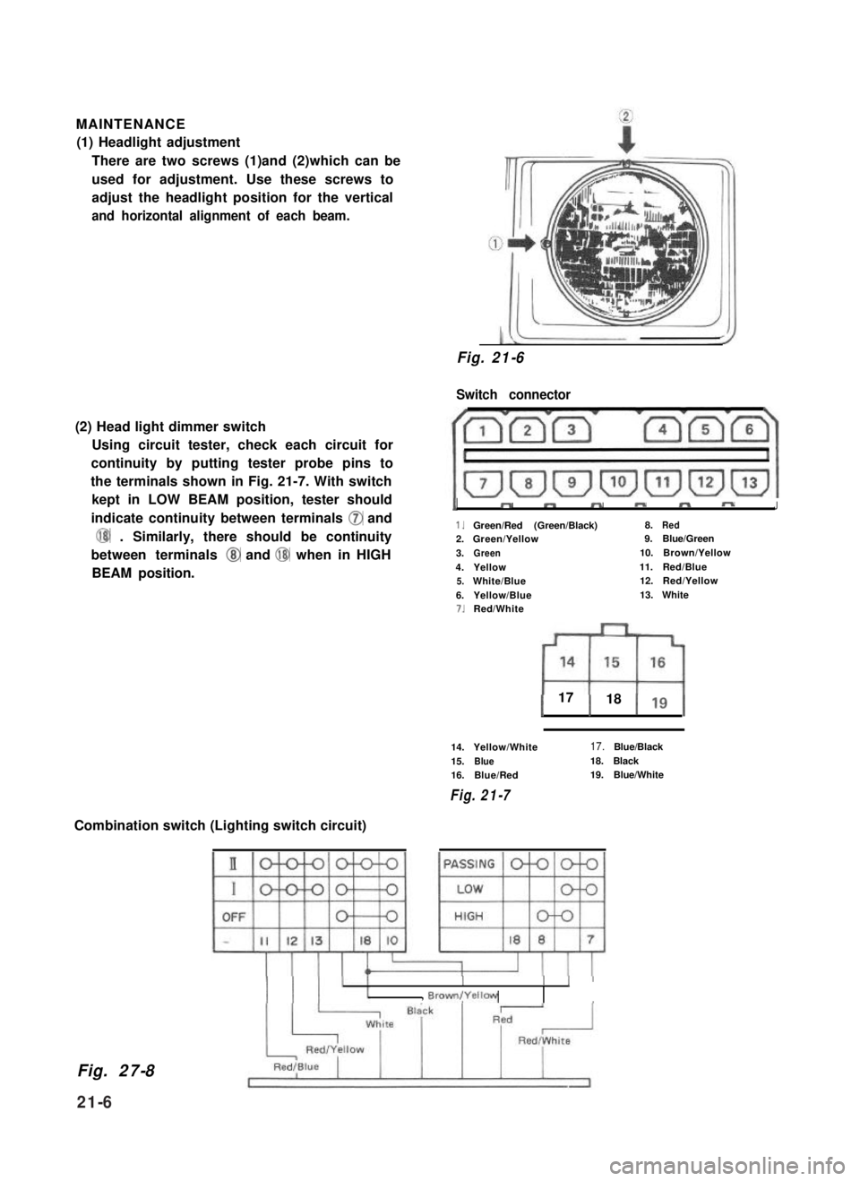
MAINTENANCE
(1) Headlight adjustment
There are two screws (1)and (2)which can be
used for adjustment. Use these screws to
adjust the headlight position for the vertical
and horizontal alignment of each beam.
(2) Head light dimmer switch
Using circuit tester, check each circuit for
continuity by putting tester probe pins to
the terminals shown in Fig. 21-7. With switch
kept in LOW BEAM position, tester should
indicate continuity between terminals 0 and
@ . Similarly, there should be continuity
between terminals @ and @ when in HIGH
BEAM position.
Fig. 21-6
Switch connector
1”mmmm-J
1.Green/Red (Green/Black)8.Red2.Green/Yellow9.Blue/Green
3.Green10.Brown/Yellow
4.Yellow11.Red/Blue
5.White/Blue12.Red/Yellow
6.Yellow/Blue13.White7.Red/White
1 17 1 18 119 1
14.Yellow/White
15.Blue16.Blue/Red
Fig. 21-7
17.Blue/Black
18.Black19.Blue/White
Combination switch (Lighting switch circuit)
Fig. 27-8
II
II I, Brown(Yellow
21-6
Page 457 of 962
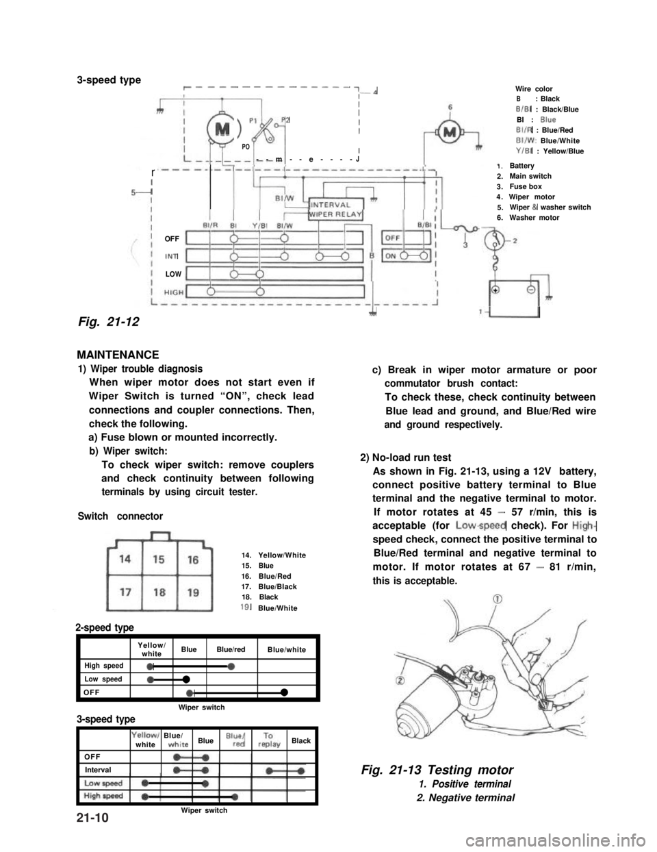
3-speed typer __-- - ---- - ---- ~-*
Fig. 21-12
rI-I
III
MI > p1p2
fil
II0POI--m--e----J
OFF
IN1
LOW
MAINTENANCE
1) Wiper trouble diagnosis
When wiper motor does not start even if
Wiper Switch is turned “ON”, check lead
connections and coupler connections. Then,
check the following.
a) Fuse blown or mounted incorrectly.
b) Wiper switch:
To check wiper switch: remove couplers
and check continuity between following
terminals by using circuit tester.
Switch connector
14.Yellow/White15.Blue16.Blue/Red17.Blue/Black18.Black
18.Blue/White
2-speed type
Yellow/whiteBlueBlue/redBlue/white
High speed0a
Low speed0l
OFFel
Wiper switch
3-speed type
OFF
Interval
Yellowl Blue/whitewhite Blue “lr”,“d/ rzay Black
1.Battery2.Main switch3.Fuse box4.Wiper motor5.Wiper & washer switch6.Washer motor
Wire colorB: BlackB/B1 : Black/BlueBI : BlueBIIR : Blue/RedBI/W: Blue/WhiteY/B1 : Yellow/Blue
2
L
+
A‘U
c) Break in wiper motor armature or poor
commutator brush contact:
To check these, check continuity between
Blue lead and ground, and Blue/Red wire
and ground respectively.
2) No-load run test
As shown in Fig. 21-13, using a 12V battery,
connect positive battery terminal to Blue
terminal and the negative terminal to motor.
If motor rotates at 45 - 57 r/min, this is
acceptable (for Lowspeed check). For High-
speed check, connect the positive terminal to
Blue/Red terminal and negative terminal to
motor. If motor rotates at 67 - 81 r/min,
this is acceptable.
Fig. 21-13 Testing motor
1. Positive terminal
2. Negative terminal
Wiper switch21-10