Page 143 of 962
3) Reinstall carburetor following normal service
procedures.
Connect emission control system hoses and
lead wires. Make specified play on accelerator
cable and refill cooling system.
4) Place transaxle gear shift lever in “Neutral”,
set parking brake and block drive wheels.
5) Start engine, and warm it up to normal
operating temperature, stop engine.
6) Be sure to check the following before idle
mixture adjustment.
l Fuel level is within round mark at the
center of level gauge.
l Valve lash is checked and adjusted accord-
ing to the maintenance schedule.
l Air cleaner has been properly installed
and is in good condition.
l All accessories (wipers, heater, lights etc)
are out of service.
l Ignition timing is within specification.
l Choke valve opens fully.
l Idle-up actuator does not operate.
7) Check and adjust idle speed to specification
if necessary.
8) Remove seal rubber of duty check coupler
and connect positive terminal of duty
meter to“Blue/Red” wire and negative
terminal to “Black/Green” wire.
9) Run engine at 1,500 - 2,000 r/min for 30
seconds and bring it to idle speed.
10) With engine running at idle speed, adjust idle
mixture adjusting screw slowly in small incre-
ment allowing time for duty to stabilize after
turning screw to obtain duty of 10 - 50.
If duty is too low, back screw out; if too
high, screw it in. After obtaining duty of
10 - 50, recheck idle speed, and adjust if
necessary.
NOTE:
If adjustment can’t be made because duty meter
indicator does not deflect, check feed back
system according to the checking procedure of
system described in section of Emission Control
System.
11) After adjustment, install seal rubber to duty
check coupler and drive in idle mixture
adjusting screw pin.
4-28
Page 144 of 962
4-2. AIR CLEANER
GENERAL DESCRIPTION
In the air cleaner case, a dry-type air cleaner element is provided for filtering.out dirt and dust from air
being drawn into the engine for combustion.
A damaged element must be replaced with a new one, since it allows dust particles to enter the engine if
used as it is. Such dust particles could cause wear to the engine inner parts and this further results in
decreased output.
Also, the element must be cleaned periodically. Dusty and dirty element causes decrease in output and
increase in fuel consumption. The dusty element even after cleaning should be replaced with a new one.
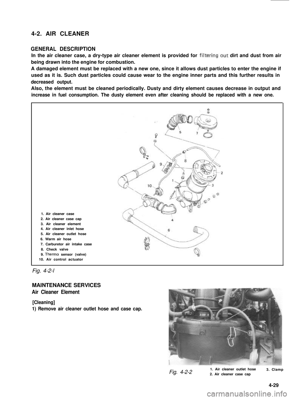
Fig. 4-2-l
1. Air cleaner case
2. Air cleaner case cap
3. Air cleaner element4. Air cleaner inlet hose
5. Air cleaner outlet hose
6. Warm air hose
7. Carburetor air intake case
8. Check valve
9. Therm0 sensor (valve)10. Air control actuator
MAINTENANCE SERVICES
Air Cleaner Element
[Cleaning]
1) Remove air cleaner outlet hose and case cap.
Fig. 4-2-21. Air cleaner outlet hose2. Air cleaner case cap3. Clamp
4-29
Page 150 of 962
![SUZUKI GRAND VITARA 1987 Service Repair Manual [Fuel tank purging procedure]
WARNING:
This purging procedure will NOT remove
all fuel vapor. Do not attempt any repair
on tank where heat or flame is required, as
an explosion resulting in personal i SUZUKI GRAND VITARA 1987 Service Repair Manual [Fuel tank purging procedure]
WARNING:
This purging procedure will NOT remove
all fuel vapor. Do not attempt any repair
on tank where heat or flame is required, as
an explosion resulting in personal i](/manual-img/20/57437/w960_57437-149.png)
[Fuel tank purging procedure]
WARNING:
This purging procedure will NOT remove
all fuel vapor. Do not attempt any repair
on tank where heat or flame is required, as
an explosion resulting in personal injury
cou Id occur.J
The following procedure is used for purging the
fuel tank.
1) After removing fuel tank, remove all hoses,
fuel level gauge from fuel tank.
2) Drain all remaining fuel from tank.
3) Move tank to flushing area.
4) Fill tank with warm water or tap water, and
agitate vigorously and drain. Repeat this
washing until inside of tank is clean.
Replace tank if inside is rusty.
5) Completely flush out remaining water after
washing.
[ Installation]
Reverse removal procedure for installation using
care for the following.
Tightening torque30-45 Nm
for fuel tank(3.0- 4.5 kg-m)
drain plug(22.0 - 32.5 lb-ft)
Refer to Fig. 4-2-5 for piping and clamp posi-
tions.
l Make sure for correct hose-to-pipe connec-
tion.
l Clamp hoses securely.
l Upon completion of installation, start engine
and check hose joints for leaks.
MAINTENANCE SERVICES
Fuel Lines
Visually inspect fuel lines and connections for
evidence of fuel leakage, hose cracking, and
damage. Make sure all clamps are secure.
Repair leaky joints, if any.
Replace hoses that are suspected of being crack-
ed.
Fig. 4-2-14
Fuel Filler (tank) Cap
Visually inspect gasket of fuel filler cap.
If it is damaged or deteriorated, replace filler cap
with new one.
NOTE:
If cap requires replacement, only a cap with
the same features should be used. Failure to
use correct cap can result in a serious malfunc-
tion of the system.
Fig. 4-2-15
1. Fuel filler cap
2. Fuel filler capgasket
Fuel Filter
As said before, this filter does not permit dis-
assembly: it is to be replaced with a new one
periodically.
Replace fuel filter referring to previous item of
“Fuel Filter Removal and Installation”.
This servicing must be performed in a well
ventilated area and away from any open
flames (such as gas hot water heaters).
4-35
Page 152 of 962
SECTION 5
EMISSION CONTROL SYSTEM
CONTENTS
5-1.GENERAL DESCRlPTlOk........................................5-4
POSITIVE CRANKCASE VENTILATION (PCV) SYSTEM........... ..5-5
THERMOSTATICALLY CONTROLLED AIR CLEANER
(TCAC) SYSTEM................................................5-6
EVAPORATIVE EMISSION CONTROL SYSTEM.....................5-7
HOT IDLE COMPENSATOR (HIC)..................................5-8
DECELERATION MIXTURE CONTROL SYSTEM....................5-9
COMPUTER CONTROLLED EMISSION CONTROL SYSTEM.........5-10
BOWL VENTILATION SYSTEM..................................5-12
FUEL CUT SYSTEM..........................................5-13
EXHAUST GAS RECIRCULATION (EGR) SYSTEM..................5-14
5-2.DIAGNOSIS......................................................5-15
5-3.MAINTENANCE SERVICE......................................5-18
PCV SYSTEM..............................................5-18
TCAC SYSTEM..............................................5-19
EVAPORATIVE EMISSION CONTROL SYSTEM...................5-20
HOT IDLE COMPENSATOR (HIC).................................5-21
DECELERATION MIXTURE CONTROL SYSTEM..................5-21
FEED BACK SYSTEM........................................5-22
SWITCH VENT SOLENOID....................................5-36
FUEL CUT SYSTEM..........................................5-36
EGR SYSTEM...............................................5-37
GENERAL..................................................5-18
5-1
5
Page 169 of 962
5-3. MAINTENANCE SERVICE
GENERAL
If the emission control hoses were disconnected
and any system component was removed for
service,be sure to reinstall the component
properly and route and connect hoses correctly
after service. Refer to Fig. 5-l-l for hose con-
nection.
PCV SYSTEM
Checking PCV System
NOTE:
If the engine is idling rough, this may be caused
by a stuck PCV valve, plugged hoses or vacuum
leakage of PCV line, therefore, never adjust the
carburetor idle without first checking the PCV
valve and hoses.
[ PCV hoses]
Check hoses for connection, leakage, clog, and
deterioration. Replace as necessary.
[ PCV valve]
Disconnect PCV hoses at three way joint.
Run engine at idle.
Place your thumb over the end of disconnect-
ed PCV hose to check for vacuum. If there is
no vacuum, check for clogged hose or valve.
Replace as necessary.
4) After checking vacuum, stop engine and check
PCV valve for sticking.
With engine stopped, ‘remove PCV hose and
connect a new hose to PCV valve.
Blow air into new hose and check that air
flows with difficulty from cylinder head side
to intake manifold side. If air flows without
difficulty, the valve is stuck in “Open”
position. Replace PCV valve. Before installing
new PCV valve to intake manifold, wind
sealing tape on thread of the valve.
WARNING:
Do not suck air through PCV valve. The
petroleum substances inside the valve and
fuel vapor inside intake manifold are
harmful.
1. PCV valve
2. New PCV hose3. Blow air
Fig. 5-3-2 Checking PCV valve for sticking
5) Connect PCV hose securely.
1. PCV valve
2. PCV hose
3. Three way joint
Fig. 5-3- 1 Checking vacuum
5-18
Page 191 of 962
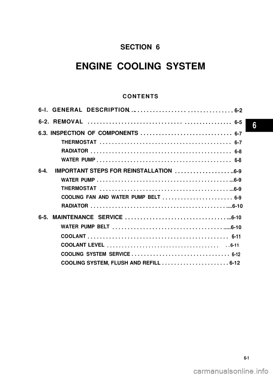
SECTION 6
ENGINE COOLING SYSTEM
CONTENTS
6-l. GENERAL DESCRIPTION .. . . . . . . . . . . . . . . . . . . . ..m..*.........6-2
6-2. REMOVAL...............................................6-5
6.3. INSPECTION OF COMPONENTS..............................6-7
THERMOSTAT...........................................6-7
RADIATOR..............................................6-8
WATER PUMP............................................6-8
6-4.IMPORTANT STEPS FOR REINSTALLATION....................6-9
WATER PUMP..............................................6-9
THERMOSTAT.............................................6-9
COOLING FAN AND WATER PUMP BELT.......................6-9
RADIATOR................................................6-10
6-5. MAINTENANCE SERVICE. . . . . . . . . . . . . . . . . . . . . . . . . . . . . . . . . ...6-10
WATER PUMP BELT.........................................6-10
COOLANT..............................................6-11
COOLANT LEVEL........................................6-11
COOLING SYSTEM SERVICE. . . . . . . . . . . . . . . . . . . . . . . . . . . . . . . .6-12
COOLING SYSTEM, FLUSH AND REFILL . . . . . . . . . . . . . . . . . . . . . . 6-12
6-1
6
Page 200 of 962
Radiator6-5. MAINTENANCE SERVICE
1) Tighten bolts securely for proper installa-
tion. Also, fix joints of 2 hoses with clamps.
Fig. 6-22
2) Install radiator shroud and cooling fan &
clutch at the same time.
3) Tighten shroud bolts and fan clutch nuts.
4) Adjust water pump belt tension.
5) Fill specified amount of coolant.
Water Pump Belt
1) Inspect belt for cracks, cuts, deformation,
wear and cleanliness. If it is necessary to
replace belt, refer to ~6-5 for procedure.
2) Check belt for tension. Belt is in proper
tension when it deflects 6 to 9 mm (0.24 -
0.35 in.) under thumb pressure (about 10 kg
or 22 lb.).
Belt tension
specification
6 - 9 mm (0:24 - 0.35 in.)
as deflectionI
Water pump pulley
Crankshaft pulley
Fig. 623
3) If belt is too tight or too loose, adjust it to
proper tension by displacing alternator
position.
Fig. 6-
4) Tighten alternator adjusting bolt and pivot
bolt.
WARNING:
All adjustments described above are to be
performed with ENGINE NOT RUNNING.
6-10
Page 211 of 962
SECTION 8
IGNITION SYSTEM
CONTENTS
8-1. GENERAL DESCRIPTION...................................8-2
DISTRIBUTOR..........................................8-3
IGNITION COIL........................................
SPARK PLUG...........................................8-4
8-2.MAINTENANCE SERVICE................................. . .8-5
HIGH TENSION CORD.....................................8-5
SPARK PLUG............................................ . . 8-5
IGNITION COIL..........................................8-5
DISTRIBUTOR..........................................8-5
IGNITION TIMING....................................... .8-9
DISTRIBUTOR DRIVE GEAR............................... .8-10
8-3.IMPORTANT REMINDERS FOR INSTALLATION.............. . 8-11
DISTRIBUTOR......................................... . .8-11
8-4
8
8-1