Page 215 of 962
8-2. MAINTENANCE SERVICEIgnition Coil
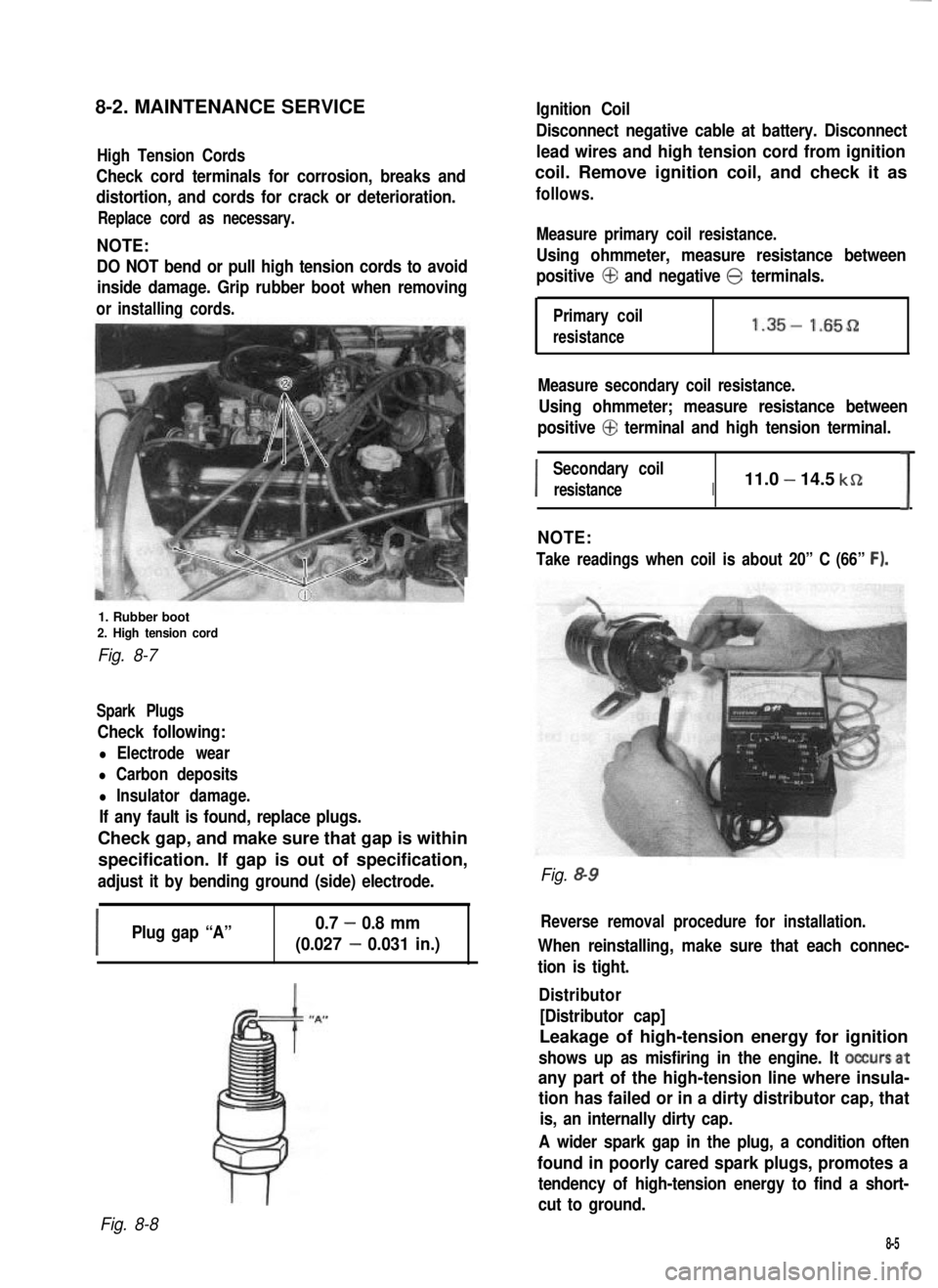
High Tension Cords
Check cord terminals for corrosion, breaks and
distortion, and cords for crack or deterioration.
Replace cord as necessary.
NOTE:
DO NOT bend or pull high tension cords to avoid
inside damage. Grip rubber boot when removing
orinstalling cords.
1. Rubber boot2. High tension cord
Fig. 8-7
Spark Plugs
Check following:
l Electrode wear
l Carbon deposits
l Insulator damage.
If any fault is found, replace plugs.
Check gap, and make sure that gap is within
specification. If gap is out of specification,
adjust it by bending ground (side) electrode.
I
Plug gap “A”0.7 - 0.8 mm
(0.027 - 0.031 in.)
Disconnect negative cable at battery. Disconnect
lead wires and high tension cord from ignition
coil. Remove ignition coil, and check it as
follows.
Measure primary coil resistance.
Using ohmmeter, measure resistance between
positive @ and negative @ terminals.
Primary coil
resistance1.35- 1.65D
Measure secondary coil resistance.
Using ohmmeter; measure resistance between
positive @ terminal and high tension terminal.
I
Secondary coil
resistanceI11.0 - 14.5 kSZ
I
NOTE:
Take readings when coil is about 20” C (66” F).
Fig. &9
Reverse removal procedure for installation.
When reinstalling, make sure that each connec-
tion is tight.
Distributor
[Distributor cap]
Leakage of high-tension energy for ignition
shows up as misfiring in the engine. It occursat
any part of the high-tension line where insula-
tion has failed or in a dirty distributor cap, that
is, an internally dirty cap.
A wider spark gap in the plug, a condition often
found in poorly cared spark plugs, promotes a
tendency of high-tension energy to find a short-
cut to ground.
Fig. 8-8
8-5
Page 253 of 962
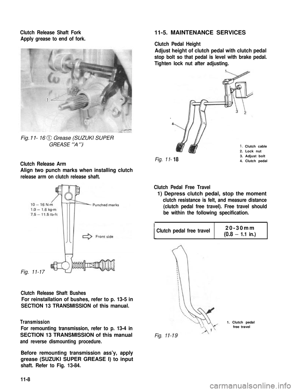
Clutch Release Shaft Fork
Apply grease to end of fork.
Fig. I l- 16 @ Grease (SUZUKI SUPER
GREASE “‘A “)
Clutch Release Arm
Align two punch marks when installing clutch
release arm on clutch release shaft.
Fig. 11-17
Clutch Release Shaft Bushes
For reinstallation of bushes, refer to p. 13-5 in
SECTION 13 TRANSMISSION of this manual.
Transmission
For remounting transmission, refer to p. 13-4 in
SECTION 13 TRANSMISSION of this manual
and reverse dismounting procedure.
11-5. MAINTENANCE SERVICES
Clutch Pedal Height
Adjust height of clutch pedal with clutch pedal
stop bolt so that pedal is level with brake pedal.
Tighten lock nut after adjusting.
.
4
I-
I- 18
1. Clutch cable2. Lock nut3. Adjust bolt4. Clutch pedalFig. 1
Clutch Pedal Free Travel
1) Depress clutch pedal, stop the moment
clutch resistance is felt, and measure distance
(clutch pedal free travel). Free travel should
be within the following specification.
!Clutch pedal free travel20-30mm
(0.8 - 1.1 in.)c
Fig. 1
1. Clutch pedalfree travel
Before remounting transmission ass’y, apply
grease (SUZUKI SUPER GREASE I) to input
shaft. Refer to Fig. 13-84.
11-8
Page 262 of 962
SECTION 13
TRANSMISSION
CONTENTS
13-l. GENERAL DESCRIPTION..................................13-1
TRANSMISSION GEAR RATIO..............................13-3
13-3. DISMOUNTING...........................................13-4
DISASSEMBLY............................................13-5
13-5. INSPECTION OF COMPONENTS............................13-12
13-6. IMPORTANT STEPS IN INSTALLATION.....................13-15
13-7. MAINTENANCE SERVICES................................13-25
13-8. RECOMMENDED TORQUE SPECIFICATION.................. 13-26
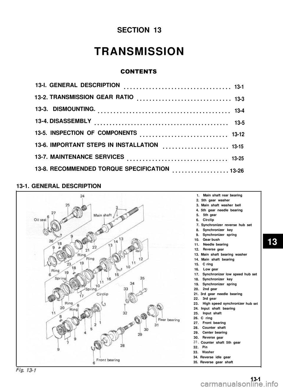
13-1. GENERAL DESCRIPTION
241.Main shaft rear bearing
2. 5th gear washer
3. Main shaft washer bell
4. 5th gear needle bearing
Oil sealfiMain shi5.5thgear
6.ICirclip
7. Synchronizer reverse hub set
8.Synchronizer key
9.Synchronizerspring
10.Gear bush
11.Needle bearing
12.Reversegear
13. Main shaft bearing washer
14. Main shaft bearing15.C ring
16.Lowgear
17.Synchronizer low speed hub set
18.Synchronizerkey
19.Synchronizerspring
20.2ndgear
F21. 3rd gear needle bearing22.3rdgear
23.hub
I
1High speed synchronizerset
I
24. Input shaft bearing25.Input shaft
i ’
IL’
ear bearing26. C ring27.AFront bearing
28.Counter shaft
429.Center bearing
930.ReversegearI i31. Counter shaft 5th gear
932.Pin
33.Washer
34. Reverse idle gear
35. Reverse gear shaft
13-1
13-2.
13-4.
13
Page 286 of 962
13-7. MAINTENANCE SERVICES
Transmission Oil
Before changing oil, check for oil leakage first
and correct defects, if any. Fill specified new oil
in specified amount.
Oil capacity1.3 litres
(2.75/2.29 US/Imp. pt.)
IOil specificationGear oil, SAE 8OW-90,75W-80
or 75W-90I
It is. highly recommended to use SAE 75W-90.
gear oil.
For viscosity chart, refer to P. I-20.
Fig. 13-85
@ Oil filler plug
@ Oil drain plup@ Oil level plug
After filling transmission with oil, torque oil
filler and drain plugs to specification.
Tightening torque N.m
for oil drain andkg-mlb-ft
filler plug18-28 1.8-2.8 13.5-20.0
Tightening torque
for oil level pluglo-161.0-1. 7.5-11.5
NOTE:
Whenever car was hoisted for any other service
work than oil change, also be sure to check for
oil leakage.
When installing oil drain and filler plugs to
transmission case,aipply sealant (SUZUKI
BOND No.1215, 99000-31110) to thread part
of plug.
13-25
Page 288 of 962
SECTION 14
TRANSFER GEAR BOX
CONTENTS
14-l.GENERAL DESCRIPTION................................. 14-2
14-2.SELECTIVE FLOWS OF TRANSFER DRIVE..................14-3
14-3.GEAR RATIO DATA . . . . . . . . . . . . . . . . . . . . . . . . . . . . . . . . . . . . . 14-4
14-4.TRANSFER SERVICES NOT REQUIRING
TRANSFER REMOVAL . . . . . . . . . . . . . . . , . . . . . . . . . . . . . . . . . . . 14-5
14-5.REMOVAL.............................................14-6
14-6.DISASSEMBLY..........................................14-8
14-7.INSPECTION OF COMPONENTS........................... 14-12
14-8.REASSEMBLY......................................... 14-14
14-9.MAINTENANCE SERVICES . . . . . . . . . . . . . . . . . . . . . . . . . . . . . . . 14-22 12
TIGHTENING TORQUE . . . . . . . . . . . . . . . . . . . . . . . . . . . . . . . . . . 14-23
14-1
14-10.
Page 309 of 962
7) Install propeller shaft flanges and tighten
nuts to specified torque and talk the nuts.
8) Upon completion of entire assembly work,
install transfer in chassis body in reverse
sequence of removal. Pour gear oil into
transfer gear box.
Refer to information given in next oil and
oil capacity for oil to be used and specified
amount.
NOTE:
When installing oil filler and drain plugs to
transfer case, apply sealant (SUZUKI BOND
No.1215, 99000-31110) to thread part of plug.
14-9. MAINTENANCE SERVICES
Oil Level
Oil level must be checked with car held in
horizontal position in both front to rear and side
to side directions.
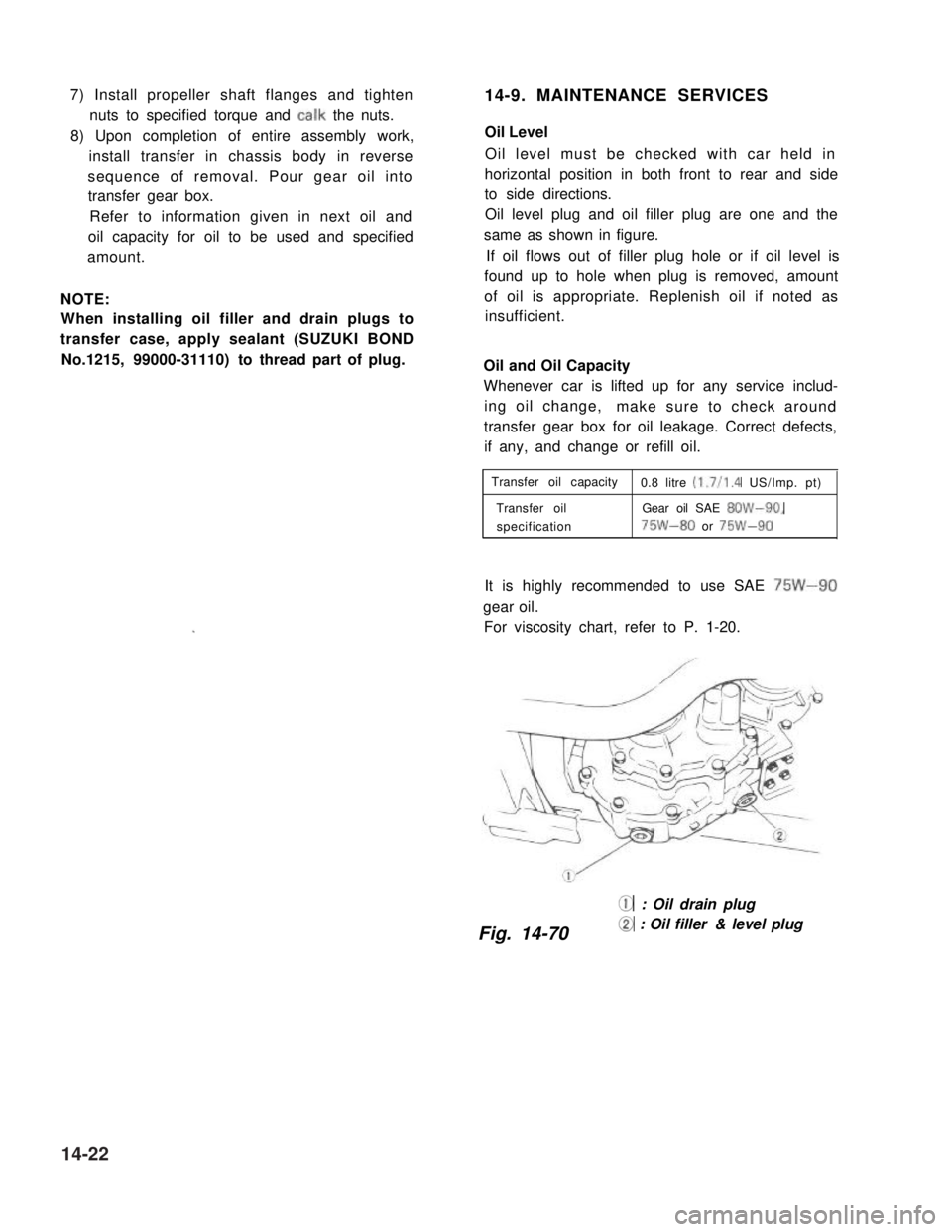
Oil level plug and oil filler plug are one and the
same as shown in figure.
If oil flows out of filler plug hole or if oil level is
found up to hole when plug is removed, amount
of oil is appropriate. Replenish oil if noted as
insufficient.
Oil and Oil Capacity
Whenever car is lifted up for any service includ-
ing oil change,make sure to check around
transfer gear box for oil leakage. Correct defects,
if any, and change or refill oil.
Transfer oil capacity0.8 litre (1.7/l .4 US/Imp. pt)
Transfer oilGear oil SAE 8OW-90,
specification75W-80 or 75W-90
It is highly recommended to use SAE 75W-90
gear oil.
For viscosity chart, refer to P. 1-20.
@ : Oil drain plug
Fig. 14-70@ : Oil filler & level plug
14-22
Page 311 of 962
SECTION 15
PROPELLER SHAFTS
CONTENTS
15-1. GENERAL DESCRIPTION..................................15-2
15-2. REMOVAL..............................................15-3
15-3. INSTALLATION.......................................... 15-3
15-4. MAINTENANCE SERVICES.................................15-4
15-5. TIGHTENING TORQUE....................................15-5
15-6. DISASSEMBLY..........................................15-6
15-7. REASSEMBLY.......................................... 15-7
15-1
Page 314 of 962
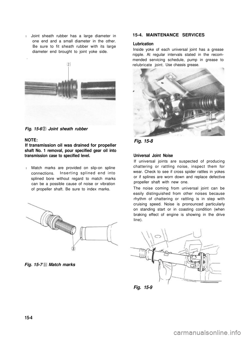
l Joint sheath rubber has a large diameter in
one end and a small diameter in the other.
Be sure to fit sheath rubber with its large
diameter end brought to joint yoke side.
.
cc
Fig. 15-6 @I Joint sheath rubber
NOTE:
If transmission oil was drained for propeller
shaft No. 1 removal, pour specified gear oil into
transmission case to specified level.
l Match marks are provided on slip-on spline
connections.Inserting splined end into
splined bore without regard to match marks
can be a possible cause of noise or vibration
of propeller shaft. Be sure to index marks.
Fig. 15-7 @I Match marks
15-4. MAINTENANCE SERVICES
Lubrication
Inside yoke of each universal joint has a grease
nipple. At regular intervals stated in the recom-
mended servicing schedule, pump in grease to
relubricate joint.Use chassis grease.
Fig. 15-8
Universal Joint Noise
If universal joints are suspected of producing
chattering or rattling noise, inspect them for
wear. Check to see if cross spider rattles in yokes
or if splines are worn down and replace defective
propeller shaft with new one.
The noise coming from universal joint can be
easily distinguished from other noises because
rhythm of chattering or rattling is in step with
cruising speed. Noise is pronounced particularly
on standing start or in coasting condition (when
braking effect of engine is showing in the drive
line).
Fig. 15-9
15-4