1987 SUZUKI GRAND VITARA tow
[x] Cancel search: towPage 20 of 962
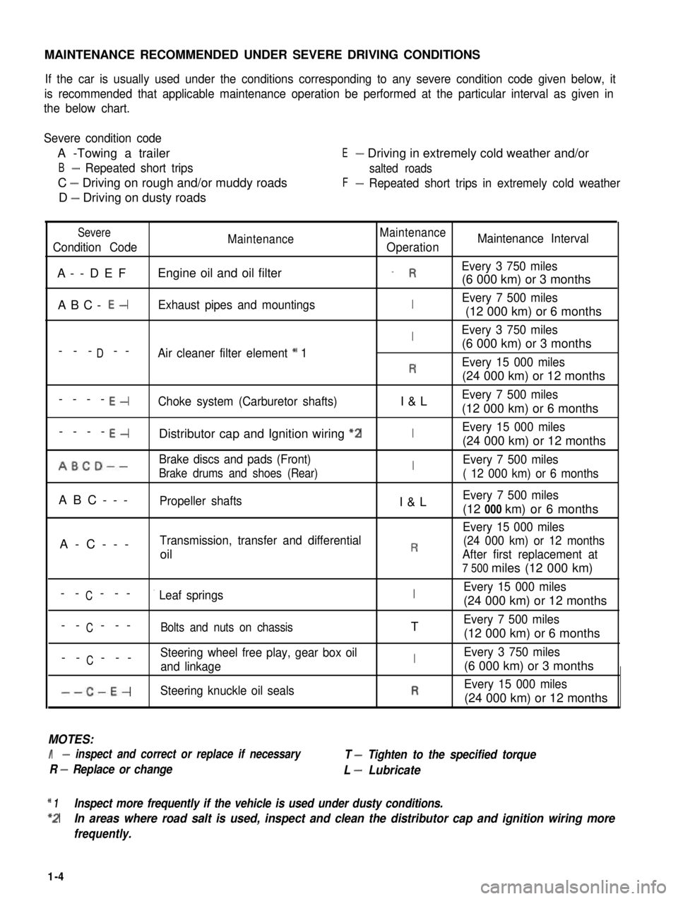
MAINTENANCE RECOMMENDED UNDER SEVERE DRIVING CONDITIONS
If the car is usually used under the conditions corresponding to any severe condition code given below, it
is recommended that applicable maintenance operation be performed at the particular interval as given in
the below chart.
Severe condition code
A -Towing a trailer
B- Repeated short trips
C - Driving on rough and/or muddy roads
D - Driving on dusty roads
E- Driving in extremely cold weather and/or
salted roads
F- Repeated short trips in extremely cold weather
Severe
Condition CodeMaintenanceMaintenance
OperationMaintenance Interval
A--DEFEngine oil and oil filter_ REvery 3 750 miles
(6 000 km) or 3 months
ABC- E-Exhaust pipes and mountingsIEvery 7 500 miles
(12 000 km) or 6 months
IEvery 3 750 miles
D(6 000 km) or 3 months--- --Air cleaner filter element * 1
REvery 15 000 miles
(24 000 km) or 12 months
----E-Choke system (Carburetor shafts)I&LEvery 7 500 miles
(12 000 km) or 6 months
----E-Distributor cap and Ignition wiring “2IEvery 15 000 miles
(24 000 km) or 12 months
ABCD--Brake discs and pads (Front)IEvery 7 500 miles
Brake drums and shoes (Rear)( 12 000 km) or 6 months
ABC---Propeller shaftsI&LEvery 7 500 miles
(12 000 km) or 6 months
Every 15 000 miles
A-C---Transmission, transfer and differential(24 000 km) or 12 months
oilRAfter first replacement at
7 500 miles (12 000 km)
CEvery 15 000 miles-- ---’ Leaf springsI(24 000 km) or 12 months
C-- ---Bolts and nuts on chassisTEvery 7 500 miles
(12 000 km) or 6 months
CSteering wheel free play, gear box oil-- ---and linkageIEvery 3 750 miles
(6 000 km) or 3 months
--C-E-Steering knuckle oil sealsREvery 15 000 miles
(24 000 km) or 12 months
MOTES:
I- inspect and correct or replace if necessary
R - Replace or change
T - Tighten to the specified torque
L - Lubricate
* 1Inspect more frequently if the vehicle is used under dusty conditions.
*2In areas where road salt is used, inspect and clean the distributor cap and ignition wiring more
frequently.
1-4
Page 27 of 962
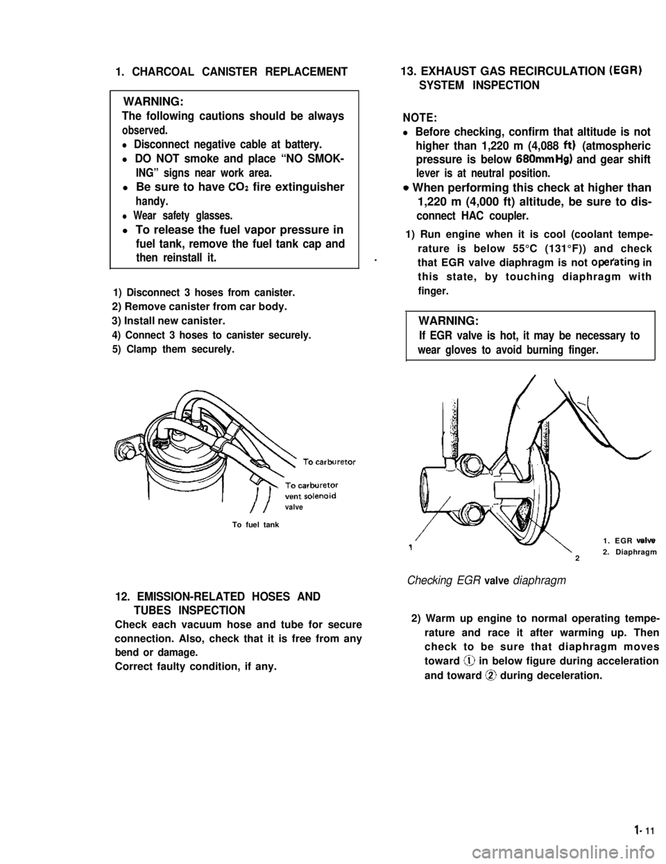
1. CHARCOAL CANISTER REPLACEMENT
WARNING:
The following cautions should be always
observed.
l Disconnect negative cable at battery.
l DO NOT smoke and place “NO SMOK-
ING” signs near work area.
l Be sure to have COZ fire extinguisher
handy.
l Wear safety glasses.
l To release the fuel vapor pressure in
fuel tank, remove the fuel tank cap and
then reinstall it.
1) Disconnect 3 hoses from canister.
2) Remove canister from car body.
3) Install new canister.
4) Connect 3 hoses to canister securely.
5) Clamp them securely.
//valve
To fuel tank
12. EMISSION-RELATED HOSES AND
TUBES INSPECTION
Check each vacuum hose and tube for secure
connection. Also, check that it is free from any
bend or damage.
Correct faulty condition, if any.
13. EXHAUST GAS RECIRCULATION (EGR)
SYSTEM INSPECTION
NOTE:
l Before checking, confirm that altitude is not
higher than 1,220 m (4,088 ftt) (atmospheric
pressure is below 680mmHg) and gear shift
lever is at neutral position.
o When performing this check at higher than
1,220 m (4,000 ft) altitude, be sure to dis-
connect HAC coupler.
.
1) Run engine when it is cool (coolant tempe-
rature is below 55°C (131°F)) and check
that EGR valve diaphragm is not operating in
this state, by touching diaphragm with
finger.
WARNING:
If EGR valve is hot, it may be necessary to
wear gloves to avoid burning finger.
1. EGR valve
22. Diaphragm
Checking EGR valve diaphragm
2) Warm up engine to normal operating tempe-
rature and race it after warming up. Then
check to be sure that diaphragm moves
toward @ in below figure during acceleration
and toward @ during deceleration.
l- 11
Page 61 of 962
3) Cylinder Head and Valve Train
The cylinder head is made of cast aluminum alloy and has four combustion chambers arranged in-line.
Each combustion chamber has an intake and an exhaust ports.
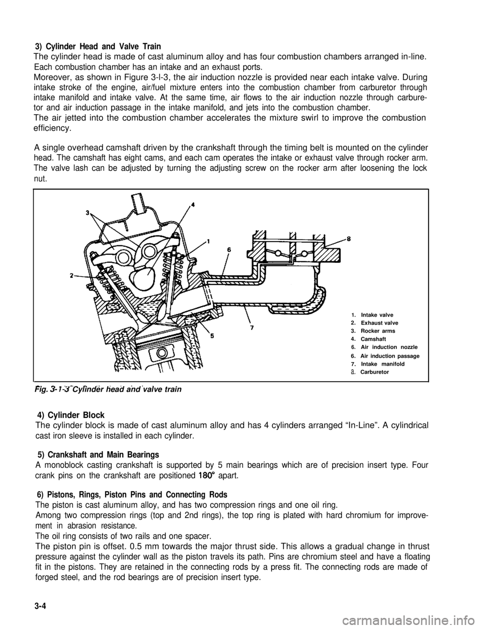
Moreover, as shown in Figure 3-l-3, the air induction nozzle is provided near each intake valve. During
intake stroke of the engine, air/fuel mixture enters into the combustion chamber from carburetor through
intake manifold and intake valve. At the same time, air flows to the air induction nozzle through carbure-
tor and air induction passage in the intake manifold, and jets into the combustion chamber.
The air jetted into the combustion chamber accelerates the mixture swirl to improve the combustion
efficiency.
A single overhead camshaft driven by the crankshaft through the timing belt is mounted on the cylinder
head. The camshaft has eight cams, and each cam operates the intake or exhaust valve through rocker arm.
The valve lash can be adjusted by turning the adjusting screw on the rocker arm after loosening the lock
nut.
2-
1.Intake valve2.Exhaust valve
3.Rocker arms
4.Camshaft
6.Air induction nozzle
6.Air induction passage
7.Intake manifold
a.Carburetor
-. - _- - ._ . . . . .Fig. 3- 7-3 Cylinder head and valve train
4) Cylinder Block
The cylinder block is made of cast aluminum alloy and has 4 cylinders arranged “In-Line”. A cylindrical
cast iron sleeve is installed in each cylinder.
5) Crankshaft and Main Bearings
A monoblock casting crankshaft is supported by 5 main bearings which are of precision insert type. Four
crank pins on the crankshaft are positioned 180” apart.
6) Pistons, Rings, Piston Pins and Connecting Rods
The piston is cast aluminum alloy, and has two compression rings and one oil ring.
Among two compression rings (top and 2nd rings), the top ring is plated with hard chromium for improve-
ment in abrasion resistance.
The oil ring consists of two rails and one spacer.
The piston pin is offset. 0.5 mm towards the major thrust side. This allows a gradual change in thrust
pressure against the cylinder wall as the piston travels its path. Pins are chromium steel and have a floating
fit in the pistons. They are retained in the connecting rods by a press fit. The connecting rods are made of
forged steel, and the rod bearings are of precision insert type.
3-4
Page 70 of 962
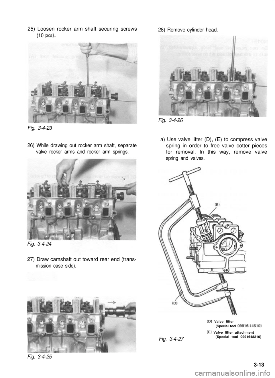
25) Loosen rocker arm shaft securing screws
(10 PCS).
Fig. 3-4-23
26) While drawing out rocker arm shaft, separate
valve rocker arms and rocker arm springs.
Fig. 3-4-24
27) Draw camshaft out toward rear end (trans-
mission case side).
28) Remove cylinder head.
____Fig. 3-4-26
a) Use valve lifter (D), (E) to compress valve
spring in order to free valve cotter pieces
for removal. In this way, remove valve
spring and valves.
(D) Valve lifter(Special tool 09916-14510)
(El Valve lifter attachment
Fig. 3-4-27(Special tool 0991648210)
Fig. 3-4-25
3-13
Page 87 of 962
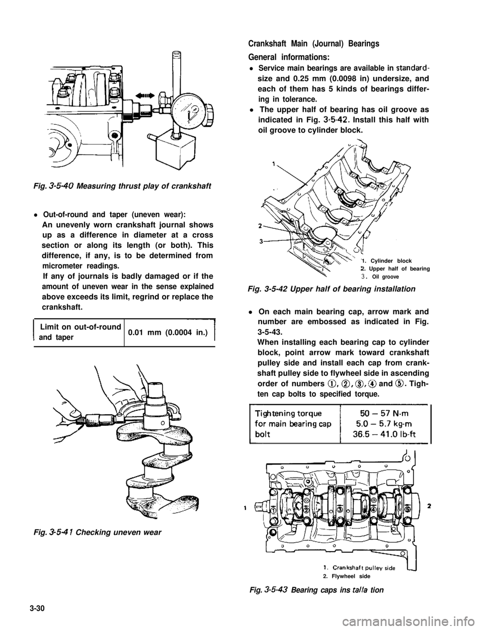
Crankshaft Main (Journal) Bearings
General informations:
l Service main bearings are available in standard-
size and 0.25 mm (0.0098 in) undersize, and
each of them has 5 kinds of bearings differ-
ing in tolerance.
l The upper half of bearing has oil groove as
indicated in Fig. 3~5-42. Install this half with
oil groove to cylinder block.
Fig. 3-5-40 Measuring thrust play of crankshaft
l Out-of-round and taper (uneven wear):
An unevenly worn crankshaft journal shows
up as a difference in diameter at a cross
section or along its length (or both). This
difference, if any, is to be determined from
micrometer readings.
If any of journals is badly damaged or if the
amount of uneven wear in the sense explained
above exceeds its limit, regrind or replace the
crankshaft.
I
Limit on out-of-round
and taper0.01 mm (0.0004 in.)
Fig. 3-5-4 1 Checking uneven wear
1. Cylinder block2. Upper half of bearing
3. Oil groove
Fig. 3-5-42 Upper half of bearing installation
l On each main bearing cap, arrow mark and
number are embossed as indicated in Fig.
3-5-43.
When installing each bearing cap to cylinder
block, point arrow mark toward crankshaft
pulley side and install each cap from crank-
shaft pulley side to flywheel side in ascending
order of numbers @,a, 0, @ and 0. Tigh-
ten cap bolts to specified torque.
3
2. Flywheel side
Fig. 3-5-43 Bearing caps ins talla tion
3-30
Page 102 of 962
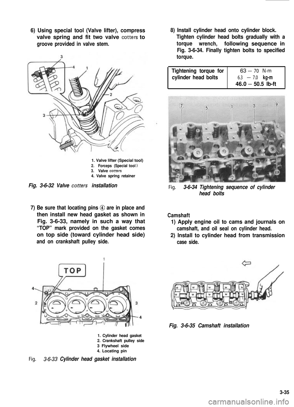
6) Using special tool (Valve lifter), compress
valve spring and fit two valve totters to
groove provided in valve stem.
1. Valve lifter (Special tool)
2.Forceps (Specialtool13.Valve totters4. Valve spring retainer
Fig. 3-6-32 Valve totters installation
7) Be sure that locating pins @ are in place and
then install new head gasket as shown in
Fig. 3-6-33, namely in such a way that
“TOP” mark provided on the gasket comes
on top side (toward cylinder head side)
and on crankshaft pulley side.
1
4
4
1. Cylinder head gasket2. Crankshaft pulley side
3 Flywheel side4. Locating pin
Fig. 3-6-33 Cylinder head gasket installation
8) Install cylinder head onto cylinder block.
Tighten cylinder head bolts gradually with a
torquewrench,following sequence in
Fig. 3-6-34. Finally tighten bolts to specified
torque.
Tightening torque for63-70 N-m
cylinder head bolts6.3-7.0 kg-m
46.0 -50.5 lb-ft
Fig. 3-6-34 Tightening sequence of cylinder
head bolts
Camshaft
1) Apply engine oil to cams and journals on
camshaft, and oil seal on cylinder head.
2) Install to cylinder head from transmission
case side.
Fig. 3-6-35 Camshaft installation
3-35
Page 171 of 962
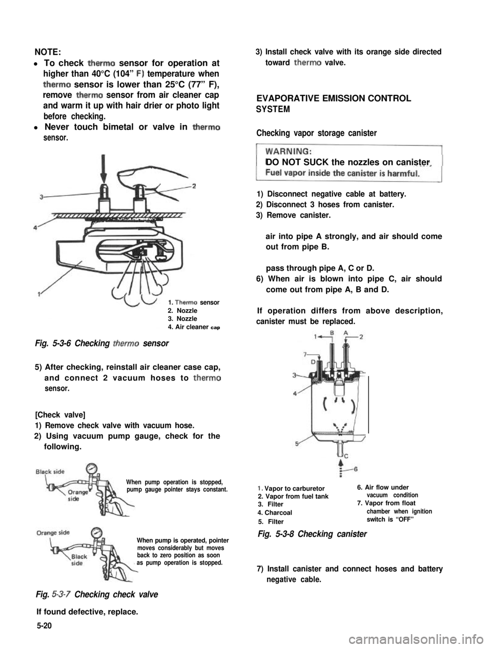
NOTE:
l To check therm0 sensor for operation at
higher than 40°C (104” F) temperature when
therm0 sensor is lower than 25°C (77” F),
remove therm0 sensor from air cleaner cap
and warm it up with hair drier or photo light
before checking.
l Never touch bimetal or valve in therm0
sensor.
1. Therm0 sensor
2. Nozzle3. Nozzle
4. Air cleaner cap
Fig. 5-3-6 Checking therm0 sensor
5) After checking, reinstall air cleaner case cap,
and connect 2 vacuum hoses to therm0
sensor.
[Check valve]
1) Remove check valve with vacuum hose.
2) Using vacuum pump gauge, check for the
following.
When pump operation is stopped,pump gauge pointer stays constant.
When pump is operated, pointermoves considerably but movesback to zero position as soonas pump operation is stopped.
Fig. 5-3-7 Checking check valve
If found defective, replace.
3) Install check valve with its orange side directed
toward therm0 valve.
EVAPORATIVE EMISSION CONTROL
SYSTEM
Checking vapor storage canister
DO NOT SUCK the nozzles on canister
1) Disconnect negative cable at battery.
2) Disconnect 3 hoses from canister.
3) Remove canister.
air into pipe A strongly, and air should come
out from pipe B.
pass through pipe A, C or D.
6) When air is blown into pipe C, air should
come out from pipe A, B and D.
If operation differs from above description,
canister must be replaced.
1. Vapor to carburetor6. Air flow under
2. Vapor from fuel tankvacuum condition
3. Filter7. Vapor from float
4. Charcoalchamber when ignition
5. Filterswitch is “OFF”
Fig. 5-3-8 Checking canister
7) Install canister and connect hoses and battery
negative cable.
5-20
Page 173 of 962
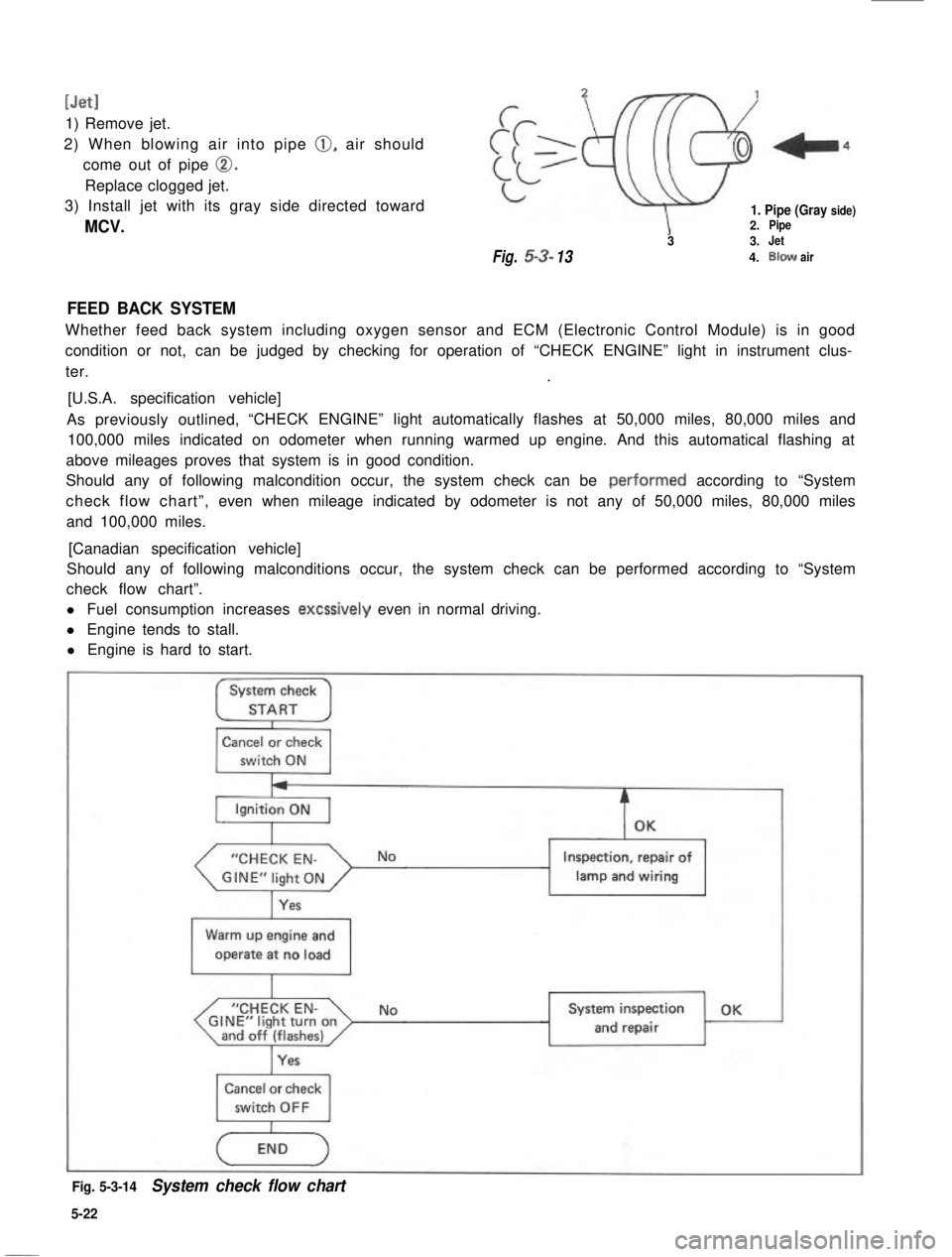
[Jet1
1) Remove jet.
2) When blowing air into pipe 0, air should
come out of pipe 0.
Replace clogged jet.
3) Install jet with its gray side directed toward
MCV.
1. Pipe (Gray side)2.Pipe
33.Jet
Fig.53-134.Blowair
FEED BACK SYSTEM
Whether feed back system including oxygen sensor and ECM (Electronic Control Module) is in good
condition or not, can be judged by checking for operation of “CHECK ENGINE” light in instrument clus-
ter..
[U.S.A. specification vehicle]
As previously outlined,“CHECK ENGINE” light automatically flashes at 50,000 miles, 80,000 miles and
100,000 miles indicated on odometer when running warmed up engine. And this automatical flashing at
above mileages proves that system is in good condition.
Should any of following malcondition occur, the system check can be .performed according to “System
check flow chart”,even when mileage indicated by odometer is not any of 50,000 miles, 80,000 miles
and 100,000 miles.
[Canadian specification vehicle]
Should any of following malconditions occur, the system check can be performed according to “System
check flow chart”.
l Fuel consumption increases excssively even in normal driving.
l Engine tends to stall.
l Engine is hard to start.
System check
STARTI
Cancel or check
switch ON
“CHECK EN-
Yes
Inspection, repair of
lamp and wiring1
Warm up engine and
operate at no load
I
“CHECK EN-GINE”light turnonand off (flashes)I
NoSystem inspection OK
and repair
Cancel or check
Fig. 5-3-14System check flow chart
5-22